EP4571094A1 - Générateur fluide - Google Patents
Générateur fluide Download PDFInfo
- Publication number
- EP4571094A1 EP4571094A1 EP23215809.7A EP23215809A EP4571094A1 EP 4571094 A1 EP4571094 A1 EP 4571094A1 EP 23215809 A EP23215809 A EP 23215809A EP 4571094 A1 EP4571094 A1 EP 4571094A1
- Authority
- EP
- European Patent Office
- Prior art keywords
- gas
- liquid
- vessel
- sequence
- vessels
- Prior art date
- Legal status (The legal status is an assumption and is not a legal conclusion. Google has not performed a legal analysis and makes no representation as to the accuracy of the status listed.)
- Pending
Links
Images

Classifications
-
- F—MECHANICAL ENGINEERING; LIGHTING; HEATING; WEAPONS; BLASTING
- F03—MACHINES OR ENGINES FOR LIQUIDS; WIND, SPRING, OR WEIGHT MOTORS; PRODUCING MECHANICAL POWER OR A REACTIVE PROPULSIVE THRUST, NOT OTHERWISE PROVIDED FOR
- F03B—MACHINES OR ENGINES FOR LIQUIDS
- F03B17/00—Other machines or engines
- F03B17/005—Installations wherein the liquid circulates in a closed loop ; Alleged perpetua mobilia of this or similar kind
-
- F—MECHANICAL ENGINEERING; LIGHTING; HEATING; WEAPONS; BLASTING
- F05—INDEXING SCHEMES RELATING TO ENGINES OR PUMPS IN VARIOUS SUBCLASSES OF CLASSES F01-F04
- F05B—INDEXING SCHEME RELATING TO WIND, SPRING, WEIGHT, INERTIA OR LIKE MOTORS, TO MACHINES OR ENGINES FOR LIQUIDS COVERED BY SUBCLASSES F03B, F03D AND F03G
- F05B2210/00—Working fluid
- F05B2210/18—Air and water being simultaneously used as working fluid
-
- F—MECHANICAL ENGINEERING; LIGHTING; HEATING; WEAPONS; BLASTING
- F05—INDEXING SCHEMES RELATING TO ENGINES OR PUMPS IN VARIOUS SUBCLASSES OF CLASSES F01-F04
- F05B—INDEXING SCHEME RELATING TO WIND, SPRING, WEIGHT, INERTIA OR LIKE MOTORS, TO MACHINES OR ENGINES FOR LIQUIDS COVERED BY SUBCLASSES F03B, F03D AND F03G
- F05B2210/00—Working fluid
- F05B2210/40—Flow geometry or direction
-
- F—MECHANICAL ENGINEERING; LIGHTING; HEATING; WEAPONS; BLASTING
- F05—INDEXING SCHEMES RELATING TO ENGINES OR PUMPS IN VARIOUS SUBCLASSES OF CLASSES F01-F04
- F05B—INDEXING SCHEME RELATING TO WIND, SPRING, WEIGHT, INERTIA OR LIKE MOTORS, TO MACHINES OR ENGINES FOR LIQUIDS COVERED BY SUBCLASSES F03B, F03D AND F03G
- F05B2240/00—Components
- F05B2240/40—Use of a multiplicity of similar components
Definitions
- the present application is directed towards a generator that utilises the properties of a compressible fluid and an incompressible fluid to generate power.
- CAES compressed air for energy storage
- a compressible fluid e.g. a compressed gas, such as compressed air
- a compressed gas such as compressed air
- this gas could potentially be used for power generation instead of being vented or otherwise disposed of as waste.
- turbine engine costs can be high due to use of exotic or specialised materials.
- a turbine engine is less efficient than a piston driven engine at idle speed and low speeds.
- a turbine is less flexible than a piston engine as a turbine typically has an optimal operating speed and therefore less responsive to changes in power demand compared with e.g. reciprocating engines.
- a generator that is driven by a compressed fluid e.g. a gas (such as air) which is flexible and inexpensive to build and maintain.
- a compressed fluid e.g. a gas (such as air) which is flexible and inexpensive to build and maintain.
- the present disclosure is directed towards a system for converting a compressed gassed into electrical power comprising: a plurality of vessels wherein the vessels are connected in a circuit by a plurality of pipe sections, wherein: each pipe section comprises a valve wherein the valves are arranged to allow liquid to flow around the pipe sections in a first direction; each pipe section comprises a generator for converting the flow of liquid in the pipe section into electricity; each vessel is configured to hold a liquid and a gas and comprises a membrane to keep the liquid separate from the gas; and a controller for sequencing power generation steps in a first sequence, wherein the device is configured to be coupled to a source of compressed gas and controller is configured to: use the source of compressed gas to increase the amount of gas in a first vessel; and reduce the amount of gas in a second vessel such that liquid flows in the circuit, whereby: electrical power is generated from the flow of liquid by at least one generator.
- the system comprises a means for controlling the pressure of gas provided to the device, wherein altering the pressure alters the power of electricity generated by the device.
- the system comprising a gas management portion, wherein the gas management portion is configured to pump gas to the first vessel and draw gas from the second vessel. More preferably, the gas management portion comprises at least one piston driven by a compressed gas.
- the gas is air and/or the liquid is water.
- the system comprises five vessels.
- the controller is configured to perform a first sequence of steps starting at a first vessel, wherein liquid is moved from each vessel in sequence. More preferably, the controller is configured to perform a second sequence of steps simultaneously with the first sequence, wherein in the second sequence, starting at a second vessel liquid is moved from each vessel in sequence, wherein the first vessel is not a neighbour of the second vessel liquid is being removed from at least two vessels while the first and second sequences of steps are being performed. Even more preferably, the second sequence is half a step out of step with the first sequence whereby liquid is constantly flowing in the circuit.
- the pipe sections are curved to form a circle.
- the generator is a rotary electrical generator.
- one or more of the bearings, brake, seal, and any other component in a piping section that requires maintenance or replacement can be accessed via an access port located externally on the piping section.
- the membrane is a diaphragm.
- one or more of the piping segments in the liquid management portion of the device may be provided with one or more gauges.
- the disclosure is also directed towards a method of generating electricity in a system comprising a plurality of vessels wherein the vessels are connected in a circuit by a plurality of pipe sections, wherein: each pipe section comprises a valve wherein the valves are arranged to allow liquid to flow around the pipe sections in a first direction; each pipe section comprises a generator for converting the flow of liquid in the pipe section into electricity; each vessel is configured to hold a liquid and a gas and comprises a membrane to keep the liquid separate from the gas, wherein the method comprises: using a source of compressed gas to increase the amount of gas in a first vessel and reducing the amount of gas in a second vessel such that liquid flows in the circuit, whereby: electrical power is generated from the flow of liquid by at least one generator.
- the present disclosure is directed to a device which forces an incompressible fluid, e.g. a liquid (such as water) to constantly flow around a fluid circuit using a compressible fluid (such as air).
- the incompressible fluid can then in turn be used to drive a generator such as a turbine (e.g. a water turbine).
- FIG. 1 shows the liquid management portion 1100 of the device.
- the liquid flow portion 1100 comprises a plurality of vessels 1101a-e for holding a liquid.
- the liquid is water.
- a first vessel 1101a is connected to a second vessel 1101b by a first piping segment 1102a.
- the first piping segment 1102a is provided with a first non-return valve 1103a.
- the first non-return valve 1103a ensures that the liquid can only flow from a first vessel 1101a to a second vessel 1101b.
- the first piping segment 1102a also comprises a first turbine 1104a.
- the first turbine 1104a is configured to generate electricity from any liquid flowing through the first pipe segment 1102a.
- the second vessel 1101b is connected to a third vessel 1101c by a second piping segment 1102b.
- the second piping segment 1102b is provided with a non-return valve 1103b.
- the non-return valve 1103b ensures that the liquid can only flow from the second vessel 1101b to the third vessel 1101c.
- the second piping segment 1102b also comprises a second turbine 1104b.
- the second turbine 1104b is configured to generate electricity from any liquid flowing through the second pipe segment 1102b.
- the third vessel 1101c is connected to a fourth vessel 1101d by a third piping segment 1102c.
- the third piping segment 1102c is also provided with a non-return valve 1103c and a turbine 1104c, which operate similarly to the non-return valves and turbines described above.
- the fourth vessel 1101d is connected to a fifth vessel 1101e by a fourth piping segment 1102d.
- the fourth piping segment 1102d is also provided with a non-return valve 1103d and a turbine 1104d, which operate similarly to the non-return valves and turbines described above.
- the fifth vessel 1101e is connected to a first vessel 1101a by a fifth piping segment 1102e.
- the fifth piping segment 1102e is also provided with a non-return valve 1103e and a turbine 1104e, which operate similarly to the non-return valves and turbines described above.
- the piping segments 1102 form a circuit 1110.
- the vessels are for holding a liquid, for example water.
- liquid has been removed from at least one vessel using a gas (e.g. air).
- a gas e.g. air
- the liquid is removed from the vessel by introducing a gas into the vessel via one or more gas pipes (not shown).
- the gas As the gas enters the vessels it forces the liquid out of the vessel.
- the remaining vessels contain a liquid (e.g. water) at ambient pressure.
- liquid can be removed from the fifth vessel 1101e.
- Gas can also be introduced into a vessel via the one or more gas pipes.
- gas is introduced into a vessel neighbouring the vessel from which liquid has been removed and gas is vented from the vessel from which liquid has been removed. This causes liquid to flow to the vessel from which liquid has been removed from the neighbouring vessel. This causes liquid to move in the pipe sections which can be converted into electricity using the generators.
- gas may be vented from the fifth vessel 1101e and gas introduced into fourth vessel 110d. As a result, liquid will flow from the fourth vessel 1101d to the fifth vessel 1101e. This movement causes liquid to flow in at least the fourth pipe section 1102d. This movement of liquid is converted into electricity using the fourth generator 1104d.
- the system is entered into a second step in the sequence.
- gas is vented from the vessel from which liquid was removed in the first step and gas introduced into its neighbouring vessel. This causes liquid to move in the pipe sections which can be converted into electricity using the generators.
- gas may be vented from the fourth vessel 1101d and gas introduced into third vessel 110c.
- liquid will flow from the third vessel 1101c to the fourth vessel 1101d. This movement causes liquid to flow in at lease the third pipe section 1102c. This movement of liquid is converted into electricity using the third generator 1104c.
- the system is entered into a third step in the sequence.
- gas is vented from the vessel from which liquid was removed in the second step and gas introduced into its neighbouring vessel. This causes liquid to move in the pipe sections which can be converted into electricity using the generators.
- gas may be vented from the third vessel 1101c and gas introduced into second vessel 110b.
- liquid will flow from the second vessel 1101b to the third vessel 1101c. This movement causes liquid to flow in at least the second pipe section 1102b. This movement of liquid is converted into electricity using the second generator 1104b.
- the system is entered into a fourth step in the sequence.
- gas is vented from the vessel from which liquid was removed in the third step and gas introduced into its neighbouring vessel. This causes liquid to move in the pipe sections which can be converted into electricity using the generators.
- gas may be vented from the second vessel 1101b and gas introduced into first vessel 110a.
- liquid will flow from the first vessel 1101a to the second vessel 1101b. This movement causes liquid to flow in at least the first pipe section 1102a. This movement of liquid is converted into electricity using the first generator 1104a.
- the system is entered into a fifth step in the sequence.
- gas is vented from the vessel from which liquid was removed in the fourth step and gas introduced into its neighbouring vessel. This causes liquid to move in the pipe sections which can be converted into electricity using the generators.
- gas may be vented from the first vessel 1101a and gas introduced into the fifth vessel 110e.
- liquid will flow from the fifth vessel 1101e to the first vessel 1101a. This movement causes liquid to flow in at least the fifth pipe section 1102e. This movement of liquid is converted into electricity using the fifth generator 1104e.
- the system After a selected time period, or alternatively when a predetermined volume of fluid has been moved during the fifth step, the system is re-entered into the first fifth step in the sequence.
- the speed of liquid flowing can be controlled by adjusting the duration of the steps in the cycle.
- the pressure applied to the liquid by the gas can be controlled through controlling the flow of gas into or out of the vessels. For example, the larger the internal radius of the gas pipes, the quicker the pressure applied to a liquid in a vessel changes after a change of step. Potentially, flow of gas into and out of the vessels may be controlled using valves.
- the use of five vessels is preferred as it allows for two sequences of steps to be run simultaneously.
- the sequences are out of phase with each other to allow continuous power generation. More preferably, the sequences are half a step out of phase.
- a second sequence may be in the middle of the fourth step.
- liquid has been removed from the fourth vessel 1101d and as gas is about to vented from this vessel, half the liquid has been moved from the first vessel 1101a to the second vessel 1101b.
- the sequencing of steps can be controlled by any suitable means.
- a processor may be used to control switching between steps.
- a membrane exists between the gas and the liquid to keep them separate. More preferably, the membrane is a diaphragm.
- a bladder is used for storing gas in the vessel. Any suitable vessel can be used, for example the Ultra-Pro range of Expansion Vessels provided by Zilmet TM may be used. Alternatively custom-built vessels can be used.
- An advantage of keeping the gas and liquid separate with a membrane is that there is no possible mixing of the gas and the liquid through either evaporation of the liquid into the gas or the gas dissolving into the liquid.
- the liquid in the unit is sealed and once fitted there is no need to 'top-up' the liquid.
- the liquid is water, there is no need to connect the system to a water supply.
- the system is sealed, it can be provided above ground, below ground, or submerged underwater. Because the liquid does not leave the system, it does not present a contamination risk to surrounding flora or fauna wherever it is located.
- the piping sections have been shown as running in straight line, however they can be curved to form an ellipse or a circle to facilitate the flow of liquid around the circuit, thereby reducing energy loss and the risk of cavitation.
- Any suitable turbine can be used to generate power.
- a rotary electrical generator is used.
- a lift-based spherical turbine is used.
- one or more of the bearings, brake, seal, and any other component in a piping section that requires maintenance or replacement can be accessed via an access port located externally on the piping section.
- Any suitable fluid valve may also be used.
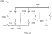
- FIG. 2 shows the gas management portion 2000 of the device.
- the gas management portion comprises a piston 2010.
- the piston is located in gas vessel 2020 and divides the interior of the gas vessel into a first chamber 2020a and a second chamber 2020b.
- the piston 2010 is driven by a driver 2015 which is configured to move the piston 2010 to increase and decrease the sizes of the first and second chambers 2020a, 2020b.
- An output pipe 2030 is connected to both the first and second chambers 2020a, 2020b, such that the connections comprise one way exit gas valves 2040.
- the exit gas valves are configured to only allow gas to leave the gas vessel 2020.
- An input pipe 2050 is also connected to the chambers 2020a, 2020b, such that the connections comprise one way entry gas valves 2060.
- the exit gas valves are configured to only allow gas to enter the gas vessel 2020.
- the volume of chamber 2020a is reduced forcing gas out of chamber 2020a via an exit gas valve 2040, and the volume of chamber 2020b is increased, drawing gas into chamber 2020b via an entry gas valve 2060.
- the volume of chamber 2020b is reduced forcing gas out of chamber 2020b via an exit gas valve 2040, and the volume of chamber 2020a is increased, drawing gas into chamber 2020a via an entry gas valve 2060.
- pressurised gas is provided to the via the output pipe 2030 to the liquid management portion of the device, and when a vessel is being depressurised, gas is drawn away from the liquid management portion of the device to be repressurised via the input pipe 2050.
- the output pipe 2030 is connected to the one or one or more first gas pipes 1110a and the one or one or more gas second pipes 1110b by a first switchable valve (not shown).
- the first switchable valve controls which vessels are being pressurised.
- the first switchable valve is in turn controlled by a controller.
- the controller can be any suitable control electronics or micro controller such as, for example, a PLC control board.
- the input pipe 2050 is connected to the one or one or more first gas pipes 1110a and the one or one or more gas second pipes 1110b by a second switchable valve (not shown).
- the second switchable valve controls which vessels are being depressurised.
- the second switchable valve is in turn controlled by a controller.
- the controller can be any suitable control electronics or micro controller such as, for example, a PLC control board.
- the controller for the second switchable valve may be the same controller as that used to control the first switchable valve.
- driver 2015 can powered the piston by any suitable means.
- driver is a double acting chamber, such as a cylinder, which powers a reciprocating movement of the piston using a compressed fluid, e.g. a gas such as air.
- Compressed air can also be used to power the switching of valves.
- the compressed air used to power the generator is preferably waste compressed air from a manufacturing plant. Alternatively compressed air can be generated using surplus electricity generated at off peak times.
- An advantage of the use of the gas management portion and the liquid management portion is that both the compressible and incompressible fluids are isolated from each other and the atmosphere. As a result, atmospheric conditions do not affect the unit.
- one or more stabilizing tanks can be connected to one or more of the piping segments.
- the stabilizing tank acts to stabilize the pressure in the liquid management portion 1100, further reducing the risk of cavitation.
- One or more of the piping segments in the liquid management portion 1100 of the device may be provided with one or more safety valves.
- one or more of the piping segments in the liquid management portion 1100 of the device may be provided with one or more gauges.
- different head hights can be mimicked by altering the pressure of compressible gas provided to the divice, e.g. through suitable pressure control valve provided between a compressed air supply and the device or the like.
- suitable pressure control valve provided between a compressed air supply and the device or the like.
- controlling the pressure of compressed air provided to the device the speed of the water flowing in the device can be adjusted.
- controlling the pressure of compressed air provided to the device can be used to control the power of electricity generated by the device (e.g. increasing the pressure of the gas increases the power supplied by the device).
- gas management portion may be omitted and compressed air can be provided to the vessels being pressurised directly from a storage tank. Gas from the vessels being depressurised may be vented to the atmosphere.
- the sizing the gas vessel 2020 relative to the sizing of the vessels 1101a-e in the liquid management portion 1100, can act as a form of gearing.
- the device can generate electricity at a variety of different scales from domestic use to industrial use, e.g. for a country's national grid, through selection of the appropriate turbines, the vessels, the number of vessels, pipe diameter of the piping sections and the interlinking of piping segments devices in a sequences.
Landscapes
- Engineering & Computer Science (AREA)
- Chemical & Material Sciences (AREA)
- Combustion & Propulsion (AREA)
- Mechanical Engineering (AREA)
- General Engineering & Computer Science (AREA)
- Other Liquid Machine Or Engine Such As Wave Power Use (AREA)
Priority Applications (2)
| Application Number | Priority Date | Filing Date | Title |
|---|---|---|---|
| EP23215809.7A EP4571094A1 (fr) | 2023-12-12 | 2023-12-12 | Générateur fluide |
| PCT/EP2024/085590 WO2025125279A1 (fr) | 2023-12-12 | 2024-12-11 | Générateur de fluide |
Applications Claiming Priority (1)
| Application Number | Priority Date | Filing Date | Title |
|---|---|---|---|
| EP23215809.7A EP4571094A1 (fr) | 2023-12-12 | 2023-12-12 | Générateur fluide |
Publications (1)
| Publication Number | Publication Date |
|---|---|
| EP4571094A1 true EP4571094A1 (fr) | 2025-06-18 |
Family
ID=89190528
Family Applications (1)
| Application Number | Title | Priority Date | Filing Date |
|---|---|---|---|
| EP23215809.7A Pending EP4571094A1 (fr) | 2023-12-12 | 2023-12-12 | Générateur fluide |
Country Status (2)
| Country | Link |
|---|---|
| EP (1) | EP4571094A1 (fr) |
| WO (1) | WO2025125279A1 (fr) |
Citations (3)
| Publication number | Priority date | Publication date | Assignee | Title |
|---|---|---|---|---|
| JPH09163640A (ja) * | 1995-12-01 | 1997-06-20 | Isao Nihei | 動力変換装置 |
| US7579700B1 (en) * | 2008-05-28 | 2009-08-25 | Moshe Meller | System and method for converting electrical energy into pressurized air and converting pressurized air into electricity |
| US20140175798A1 (en) * | 2012-12-20 | 2014-06-26 | Howard G. Hoose, JR. | Power generation system and method of use thereof |
-
2023
- 2023-12-12 EP EP23215809.7A patent/EP4571094A1/fr active Pending
-
2024
- 2024-12-11 WO PCT/EP2024/085590 patent/WO2025125279A1/fr active Pending
Patent Citations (3)
| Publication number | Priority date | Publication date | Assignee | Title |
|---|---|---|---|---|
| JPH09163640A (ja) * | 1995-12-01 | 1997-06-20 | Isao Nihei | 動力変換装置 |
| US7579700B1 (en) * | 2008-05-28 | 2009-08-25 | Moshe Meller | System and method for converting electrical energy into pressurized air and converting pressurized air into electricity |
| US20140175798A1 (en) * | 2012-12-20 | 2014-06-26 | Howard G. Hoose, JR. | Power generation system and method of use thereof |
Also Published As
| Publication number | Publication date |
|---|---|
| WO2025125279A1 (fr) | 2025-06-19 |
Similar Documents
| Publication | Publication Date | Title |
|---|---|---|
| US8209974B2 (en) | Systems and methods for energy storage and recovery using compressed gas | |
| US8479502B2 (en) | Increased power in compressed-gas energy storage and recovery | |
| US8578708B2 (en) | Fluid-flow control in energy storage and recovery systems | |
| EP1839975B1 (fr) | Système compresseur d'hydrogène | |
| US20110296823A1 (en) | Systems and methods for energy storage and recovery using gas expansion and compression | |
| US20120047884A1 (en) | High-efficiency energy-conversion based on fluid expansion and compression | |
| PL85439B1 (fr) | ||
| US20200325891A1 (en) | Compressed air energy storage generator | |
| CN1138152A (zh) | 液化气体供给系统 | |
| JP7721808B2 (ja) | 熱機関システム | |
| EP4571094A1 (fr) | Générateur fluide | |
| US20160091000A1 (en) | Device for the storage and generation of power | |
| US11686304B2 (en) | Reciprocating compressor-expander | |
| US20250290472A1 (en) | Internal combustion engine system, movable body, and method of supplying fuel to fuel consumption apparatus | |
| KR101870053B1 (ko) | 선박용 구동 시스템, 구동 시스템 작동 방법 및 구동 시스템을 갖는 선박 | |
| EP4698817A1 (fr) | Procédé et système de stockage d'hydrogène | |
| JP5908056B2 (ja) | ガス焚きエンジン | |
| AU2020376582A1 (en) | System for supplying hydrogen gas to engine | |
| US20250297602A1 (en) | Device for providing hydrogen | |
| JP6038225B2 (ja) | ガス焚きエンジン | |
| US11585270B1 (en) | Energy storage system and method | |
| WO2024263139A1 (fr) | Système de turbine | |
| KR102016524B1 (ko) | 부유식 가스 발전 플랜트 | |
| WO2025032820A1 (fr) | Dispositif de production d'énergie | |
| GB2426294A (en) | Power generation system |
Legal Events
| Date | Code | Title | Description |
|---|---|---|---|
| PUAI | Public reference made under article 153(3) epc to a published international application that has entered the european phase |
Free format text: ORIGINAL CODE: 0009012 |
|
| STAA | Information on the status of an ep patent application or granted ep patent |
Free format text: STATUS: THE APPLICATION HAS BEEN PUBLISHED |
|
| AK | Designated contracting states |
Kind code of ref document: A1 Designated state(s): AL AT BE BG CH CY CZ DE DK EE ES FI FR GB GR HR HU IE IS IT LI LT LU LV MC ME MK MT NL NO PL PT RO RS SE SI SK SM TR |
|
| STAA | Information on the status of an ep patent application or granted ep patent |
Free format text: STATUS: THE APPLICATION IS DEEMED TO BE WITHDRAWN |