EP4571125A1 - Elément de liaison pour relier au moins deux éléments de construction à profilés pliés ou arrondis - Google Patents
Elément de liaison pour relier au moins deux éléments de construction à profilés pliés ou arrondis Download PDFInfo
- Publication number
- EP4571125A1 EP4571125A1 EP24216258.4A EP24216258A EP4571125A1 EP 4571125 A1 EP4571125 A1 EP 4571125A1 EP 24216258 A EP24216258 A EP 24216258A EP 4571125 A1 EP4571125 A1 EP 4571125A1
- Authority
- EP
- European Patent Office
- Prior art keywords
- connecting element
- base body
- contact surfaces
- central base
- projections
- Prior art date
- Legal status (The legal status is an assumption and is not a legal conclusion. Google has not performed a legal analysis and makes no representation as to the accuracy of the status listed.)
- Pending
Links
Images


Classifications
-
- F—MECHANICAL ENGINEERING; LIGHTING; HEATING; WEAPONS; BLASTING
- F16—ENGINEERING ELEMENTS AND UNITS; GENERAL MEASURES FOR PRODUCING AND MAINTAINING EFFECTIVE FUNCTIONING OF MACHINES OR INSTALLATIONS; THERMAL INSULATION IN GENERAL
- F16B—DEVICES FOR FASTENING OR SECURING CONSTRUCTIONAL ELEMENTS OR MACHINE PARTS TOGETHER, e.g. NAILS, BOLTS, CIRCLIPS, CLAMPS, CLIPS OR WEDGES; JOINTS OR JOINTING
- F16B5/00—Joining sheets or plates, e.g. panels, to one another or to strips or bars parallel to them
- F16B5/06—Joining sheets or plates, e.g. panels, to one another or to strips or bars parallel to them by means of clamps or clips
- F16B5/0607—Joining sheets or plates, e.g. panels, to one another or to strips or bars parallel to them by means of clamps or clips joining sheets or plates to each other
- F16B5/0621—Joining sheets or plates, e.g. panels, to one another or to strips or bars parallel to them by means of clamps or clips joining sheets or plates to each other in parallel relationship
-
- F—MECHANICAL ENGINEERING; LIGHTING; HEATING; WEAPONS; BLASTING
- F16—ENGINEERING ELEMENTS AND UNITS; GENERAL MEASURES FOR PRODUCING AND MAINTAINING EFFECTIVE FUNCTIONING OF MACHINES OR INSTALLATIONS; THERMAL INSULATION IN GENERAL
- F16B—DEVICES FOR FASTENING OR SECURING CONSTRUCTIONAL ELEMENTS OR MACHINE PARTS TOGETHER, e.g. NAILS, BOLTS, CIRCLIPS, CLAMPS, CLIPS OR WEDGES; JOINTS OR JOINTING
- F16B2/00—Friction-grip releasable fastenings
- F16B2/20—Clips, i.e. with gripping action effected solely by the inherent resistance to deformation of the material of the fastening
- F16B2/22—Clips, i.e. with gripping action effected solely by the inherent resistance to deformation of the material of the fastening of resilient material, e.g. rubbery material
-
- F—MECHANICAL ENGINEERING; LIGHTING; HEATING; WEAPONS; BLASTING
- F16—ENGINEERING ELEMENTS AND UNITS; GENERAL MEASURES FOR PRODUCING AND MAINTAINING EFFECTIVE FUNCTIONING OF MACHINES OR INSTALLATIONS; THERMAL INSULATION IN GENERAL
- F16B—DEVICES FOR FASTENING OR SECURING CONSTRUCTIONAL ELEMENTS OR MACHINE PARTS TOGETHER, e.g. NAILS, BOLTS, CIRCLIPS, CLAMPS, CLIPS OR WEDGES; JOINTS OR JOINTING
- F16B5/00—Joining sheets or plates, e.g. panels, to one another or to strips or bars parallel to them
- F16B5/0004—Joining sheets, plates or panels in abutting relationship
- F16B5/0032—Joining sheets, plates or panels in abutting relationship by moving the sheets, plates, or panels or the interlocking key parallel to the abutting edge
- F16B5/004—Joining sheets, plates or panels in abutting relationship by moving the sheets, plates, or panels or the interlocking key parallel to the abutting edge and using C-shaped clamps
-
- F—MECHANICAL ENGINEERING; LIGHTING; HEATING; WEAPONS; BLASTING
- F16—ENGINEERING ELEMENTS AND UNITS; GENERAL MEASURES FOR PRODUCING AND MAINTAINING EFFECTIVE FUNCTIONING OF MACHINES OR INSTALLATIONS; THERMAL INSULATION IN GENERAL
- F16B—DEVICES FOR FASTENING OR SECURING CONSTRUCTIONAL ELEMENTS OR MACHINE PARTS TOGETHER, e.g. NAILS, BOLTS, CIRCLIPS, CLAMPS, CLIPS OR WEDGES; JOINTS OR JOINTING
- F16B5/00—Joining sheets or plates, e.g. panels, to one another or to strips or bars parallel to them
- F16B5/06—Joining sheets or plates, e.g. panels, to one another or to strips or bars parallel to them by means of clamps or clips
- F16B5/0607—Joining sheets or plates, e.g. panels, to one another or to strips or bars parallel to them by means of clamps or clips joining sheets or plates to each other
- F16B5/0621—Joining sheets or plates, e.g. panels, to one another or to strips or bars parallel to them by means of clamps or clips joining sheets or plates to each other in parallel relationship
- F16B5/0635—Joining sheets or plates, e.g. panels, to one another or to strips or bars parallel to them by means of clamps or clips joining sheets or plates to each other in parallel relationship fastened over the edges of the sheets or plates
-
- F—MECHANICAL ENGINEERING; LIGHTING; HEATING; WEAPONS; BLASTING
- F16—ENGINEERING ELEMENTS AND UNITS; GENERAL MEASURES FOR PRODUCING AND MAINTAINING EFFECTIVE FUNCTIONING OF MACHINES OR INSTALLATIONS; THERMAL INSULATION IN GENERAL
- F16B—DEVICES FOR FASTENING OR SECURING CONSTRUCTIONAL ELEMENTS OR MACHINE PARTS TOGETHER, e.g. NAILS, BOLTS, CIRCLIPS, CLAMPS, CLIPS OR WEDGES; JOINTS OR JOINTING
- F16B5/00—Joining sheets or plates, e.g. panels, to one another or to strips or bars parallel to them
- F16B5/06—Joining sheets or plates, e.g. panels, to one another or to strips or bars parallel to them by means of clamps or clips
- F16B5/0607—Joining sheets or plates, e.g. panels, to one another or to strips or bars parallel to them by means of clamps or clips joining sheets or plates to each other
- F16B5/0621—Joining sheets or plates, e.g. panels, to one another or to strips or bars parallel to them by means of clamps or clips joining sheets or plates to each other in parallel relationship
- F16B5/065—Joining sheets or plates, e.g. panels, to one another or to strips or bars parallel to them by means of clamps or clips joining sheets or plates to each other in parallel relationship the plates being one on top of the other and distanced from each other, e.g. by using protrusions to keep contact and distance
Definitions
- the invention relates to a connecting element for connecting at least two components with bevelled and/or rounded profiles.
- the invention relates to a method for producing a connecting element.
- the invention relates to an assembly comprising a first component with at least one first beveled and/or rounded profile, a second component with at least one second beveled and/or rounded profile and at least one connecting element.
- the invention relates to a food transport container comprising an outer body, an inner body and an assembly.
- Well-known connecting elements are used in food transport containers, for example to connect two sheets with a bent profile.
- Such a connecting element is known, for example, from EP 1 754 895 B1 It shows a two-part connecting element consisting of an outer base element into which the sheets with beveled profiles can be inserted.
- An inner element with a dovetail profile is used to secure the sheets, which secures the sheets in the base element by means of the dovetail.
- a disadvantage of this design is that the connecting element consists of two components, which makes manufacturing complex.
- the one-piece connecting element can only be manufactured with considerable effort and/or expense.
- manufacturing with an extruder tool is complex, as the necessary cooling of the extruder tool is difficult to ensure.
- An object of the present invention is therefore to provide a connecting element that can be manufactured simply and inexpensively. Furthermore, a simple and cost-effective method for manufacturing a connecting element, as well as an assembly comprising a connecting element and a food transport trolley comprising an assembly, each of which can be manufactured simply and inexpensively, are to be specified.
- Another object of the present invention is to provide an alternative connecting element, an alternative assembly, an alternative method of manufacturing a connecting element and an alternative food transport trolley.
- the present invention achieves the above-mentioned objects in a connecting element for connecting at least two components with beveled and/or rounded profiles, in particular for use in a food transport container, comprising a central base body, wherein at least two outer projections are arranged laterally on the central base body, wherein the central base body and the at least two outer projections are formed in one piece, wherein the central base body has at least two first and at least two second contact surfaces for the contact of the at least two beveled and/or rounded components, wherein the first contact surfaces are arranged at an angle to the second contact surfaces, in that an inner projection is arranged between the central base body and the outer projections.
- the present invention achieves the above-mentioned objects by a method for producing a connecting element according to one of claims 1 to 12, wherein the connecting element is produced by extrusion.
- the present invention achieves the above-mentioned objects by means of an assembly comprising a first component having at least one first beveled and/or rounded profile, a second component having at least one second beveled and/or rounded profile and at least one connecting element according to one of claims 1 to 12, wherein the first beveled and/or rounded profile and the second beveled and/or rounded profile can be connected in a form-fitting manner by means of the connecting element.
- the present invention achieves the above-mentioned objects by a food transport container comprising an outer body, an inner body and an assembly according to claim 14, wherein the outer body comprises the first component of the assembly and wherein the inner body comprises the second component of the assembly, and wherein the outer body and the inner body are connectable by the assembly.
- the inner and outer projections can provide a connecting profile that can, for example, reliably secure sheets with bent and/or rounded profiles and can also be easily manufactured, for example by extrusion.
- an extruder tool can be sufficiently cooled, particularly by cavities between the inner and outer projections, thus simplifying production.
- the contact area between the sheets and the connecting tool is reduced, making it easier to compensate for fluctuations in sheet thickness, for example by coating.
- Another advantage is that the contact surface between the connecting element and the components is reduced, thus reducing friction and simplifying assembly.
- the connecting element can be mushroom-shaped.
- Components with beveled and/or rounded profiles, such as sheet metal, can be secured in a cavity between the base body and the inner projections.
- the components can be secured in a horizontal direction by the base body and the inner projections, and in a vertical direction The direction can be determined by the base body and the outer projections.
- the connecting element can be pushed onto the components.
- first contact surfaces are arranged obliquely to the second contact surfaces
- first and second contact surfaces are not arranged parallel to one another.
- planes through the first and second contact surfaces can each intersect at an angle.
- first and/or second contact surfaces can be rounded and thus also arranged obliquely to one another.
- bent profile is to be understood in the broadest sense and refers, particularly in the claims, preferably in the description, to a component that is bent or folded in at least one direction. It is therefore not a purely plate-shaped component, but rather a bent or folded component.
- a bent profile also includes a component that is bent in such a way that a curve is created between the end regions of the component. It is also conceivable that the component is bent in such a way that a folded edge is created between the end regions of the component.
- food transport container is to be understood in the broadest sense and refers, particularly in the claims, preferably in the description, also to tray transport trolleys, TTW, or in particular to mobile cooking stations.
- the base body is designed as a web.
- the web can be T-shaped.
- the inner and outer projections can protrude or extend from the web.
- two extensions are formed on an end region of the central base body, wherein the second contact surfaces are arranged on the two extensions.
- the end region of the central base body on which extensions are arranged is arranged, in particular, opposite an end region of the base body from which the inner and outer projections protrude.
- the extensions are particularly suitable for limiting movement of the components in the vertical direction.
- the extensions have the second contact surfaces at which the components can contact the base body.
- the second contact surfaces are at least partially rounded, wherein the rounding each extends over an angle of more than 45°, preferably more than 65°, in particular more than 85°.
- the extensions can extend perpendicular to a main extension direction of the base body.
- the contact surfaces can in particular be arranged exclusively on the extensions or extend beyond the extensions.
- the rounding can accordingly also be formed exclusively on the extensions or extend beyond the extensions. If the contact surfaces extend beyond the extensions, a transition results which can be at least partially, in particular completely, rounded.
- the contact surface can comprise only part of the transition or the entire transition. It is possible for the contact surfaces to be arranged on the extensions and/or the transitions.
- One advantage of this is that the components to be connected with the connecting element can be manufactured easily, since, for example, the components can be beveled simply by bending them.
- a main extension direction of the central base body is parallel to a main extension direction of the inner projections.
- the inner projections protrude in the same direction as the central base body. This creates a cavity between the central base body and the inner projections with a width that is essentially constant along the main extension direction of the central base body.
- the cavity is particularly suitable for accommodating a plate-shaped component.
- the outer projections have third contact surfaces for engaging the at least two components, wherein the third contact surfaces are arranged perpendicular to the first contact surfaces.
- the inner projections have fourth contact surfaces for engaging the at least two components, wherein the fourth contact surfaces are arranged parallel to the first contact surfaces.
- the height of the inner projections corresponds to at least 5%, in particular at least 10%, preferably at least 20% of the height of the central base body.
- the components are secured by the connecting element, in particular between the central base body and the inner projections.
- the minimal height of the inner projections enlarges the cavity between the inner projections and the central base body, into which the components can engage. This reduces the likelihood of the components slipping out of the connecting element.
- the inner projections are formed integrally with the central base body and the outer projections.
- the entire connecting element is formed integrally.
- a cavity in particular U-shaped in cross-section, is formed between the central base body and the inner projections for receiving the components, in particular in a form-fitting manner.
- This cavity extends over at least 60%, preferably at least 80%, in particular over the entire length of the connecting element.
- the term "length of the connecting element” refers in particular to the extension of the connecting element in the direction of insertion, in particular sliding, of the connecting element onto the components. A required length of the cavities can ensure that the connecting element can be pushed onto the components over a desired length.
- the connecting element is made at least partially, in particular entirely, of polyamide, in particular fiber-reinforced polyamide. This allows the production of a connecting element with high thermal and mechanical strength.
- the at least two outer projections together have a semicircular profile.
- the connecting element can be manufactured easily.
- the semicircular shape creates a cavity between the outer projections and the central base body, so that sufficient cooling can be provided for the manufacturing tool, for example, during a manufacturing process using extrusion or injection molding.
- the height of the connecting element which is defined as the extension of the connecting element in the direction of the main extension direction of the central base body, is less than the width of the connecting element, which is defined as the extension of the connecting element perpendicular to the height of the connecting element and extending from a first outer projection to a second outer projection.
- the third contact surfaces arranged on the outer projections are spaced apart by a large distance relative to the height of the connecting element.
- the connecting element is designed symmetrically to an axis along the main extension direction of the central base body.
- the connecting element can be manufactured particularly easily.
- the connecting element can connect components of the same design.
- the outer projections are longer than the inner projections.
- the extension of the outer projections parallel to a main extension direction of the base body is greater than the extension of the inner projections parallel to the main extension direction of the base body.
- the connecting element can be pushed onto the first and second beveled and/or rounded profiles.
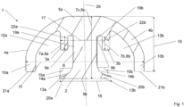
- Figure 1 shows a connecting element in cross section according to an embodiment of the present invention.
- the connecting element 1 in the Figure 1 comprises a central base body 2, inner projections 3a, 3b, and outer projections 4a, 4b.
- the central base body 2 is rectangular, in particular "T-shaped," wherein the central base body 2 is wider in an upper end region 5a than in the center 6 of the central base body 2.
- the main extension direction 7c of the central base body 2 is defined as the direction of extension of the base body 2 from the upper end region 5a to the lower end region 5b.
- the inner projections 3a, 3b are arranged at the upper end region 5a of the base body 2 and are rectangular in shape.
- the inner projections 3a, 3b extend parallel to the central base body 2.
- the length 8a, 8b of the inner projections 3a, 3b is between 10% and 40% of the height 8c of the central base body 2.
- the height 8c of the central base body 2 is the extension of the central base body 2 in the direction of the main extension direction 7c.
- the inner projections 3a, 3b are designed or arranged such that a cavity 9a, 9b is formed between each of the inner projections 3a, 3b and the central base body 2, which cavity is in particular rectangular.
- the inner projections 3a, 3b together with the central base body 2 form the cavities 9a, 9b.
- the cavities 9a, 9b are in particular designed to accommodate components (in Figure 1 not shown).
- the outer projections 4a, 4b are also arranged on the central base body 2.
- the outer projections 4a, 4b are curved.
- the outer projections 4a, 4b are each substantially quarter-circular in shape.
- the projections 4a, 4b together thus substantially form a semicircle or, together with the upper flat or flattened end region 5a of the central base body 2, form a semicircle.
- the projections 4a, 4b extend outward on the central base body 2 perpendicular to the main extension direction 7c of the central base body 2.
- the outer projections 4a, 4b curve toward the lower end region 5b of the base element 2, so that the end regions 10a, 10b of the outer projections 4a, 4b extend parallel to the main extension direction 7c of the central base body 2.
- the connecting element 1 is thus essentially mushroom-shaped.
- the outer projections 4a, 4b extend in a straight line and obliquely away from the base body 2 or that the outer projections 4a, 4b do not curve continuously into the end region 10a, but initially extend in a straight line transversely to the main extension direction 7c of the base body 2 and are then folded or bent so that the end regions 10a, 10b again extend parallel to the main extension direction 7c of the base body 2.
- the width 11 of the connecting element 1, i.e. the extension between the end regions 10a, 10b of the outer projections 4a, 4b, is greater than the height 8c of the base body 2 and thus than the height of the connecting element 1.
- Cavities 12a, 12b are provided between the outer projections 4a, 4b and the central base body 2. These cavities 12a, 12b enable by means of extrusion or injection molding, better cooling of the extrusion or injection molding tool is achieved. In particular, this enables a one-piece design or production of the connecting element 1.
- the height 18 of the outer projections 4a, 4b is defined as the extension of the outer projections 4a, 4b in the direction of the main extension direction 7c from the upper end region 5a to the end regions 10a, 10b of the outer projections 4a, 4b.
- the height 18 of the outer projections 4a, 4b is smaller than the height 8c of the central base body 2, so that there is space for inserting components between the end regions 10a, 10b of the outer projections 4a, 4b and extensions 13a, 13b of the base body 2.
- the two extensions 13a, 13b are provided at the lower end region 5b of the base body 2.
- the extensions 13a, 13b extend outward from the base body 2, perpendicular to the main extension direction 7c of the base body 2.
- the transition 14a, 14b to the extensions 13a, 13b is rounded.
- the rounding extends, in particular, over an angle 15a, 15b between 45° and 90°. It is also conceivable for the transition 14a, 14b not to be rounded, but to be completely or partially angular.
- the length 16 between the extensions 13a, 13b corresponds to 80% to 120% of the length 17 between the inner projections 3a, 3b.
- first contact surfaces 19a, 19b, second contact surfaces 20a, 20b, third contact surfaces 21a, 21b, and fourth contact surfaces 22a, 22b are provided.
- the first contact surfaces 19a, 19b are formed on the central base body 2 at the same height as the inner projections 3a, 3b.
- the second contact surfaces 20a, 20b are provided on the upper sides of the extensions 13a, 13b, i.e., the sides facing in the direction of the inner projections 3a, 3b, in particular at the transitions 14a, 14b.
- the third contact surfaces 21a, 21b are formed or arranged on the undersides of the outer projections 4a, 4b, i.e., the sides facing in the direction of the extensions 13a, 13b.
- the fourth contact surfaces 22a, 22b are provided on the inner sides of the inner projections 3a, 3b, i.e. the sides that point in the direction of the base body 2.
- the first contact surfaces 19a, 19b are formed obliquely compared to the second contact surfaces 20a, 20b.
- the second contact surface 20a, 20b can be arranged on the extensions 13a, 13b so that it is oriented in a different direction. Since the various contact surfaces 19a, 19b and 20a, 20b point in different directions, it is ensured that they can prevent the component from shifting in different directions.
- the connecting element 1 is in particular axially symmetrical, with the axis of symmetry 29 passing through the base body 2 parallel to the main extension direction 7c.
- Figure 2 shows in cross section an assembly according to an embodiment of the present invention.
- FIG 2 an assembly 25 comprising a connecting element 1 and a component 23 is shown, wherein the component 23 is fixed in the connecting element 1. It is possible for the assembly 25 to comprise a second component (not shown), which can also be fixed in the connecting element 1. For the sake of simplicity, only one component 23 is shown here.
- the connecting element 1 can in particular correspond to the connecting element 1 according to Figure 1 are equivalent to.
- the component 23 is plate-shaped and profiled, for example, it can be made of sheet metal. Profiled in the context of Figure 2 In particular, the component 23 is not linear, but curved. The component has a first region 24a and a second region 24b, which are arranged at an angle of approximately 90° to one another. The transition between the first region 24a and the second region 24b is rounded. For example, such a component can be produced by bending a plate-shaped sheet metal. In particular, the curvature of the component 23 corresponds to the curvature of the transitions 14a, 14b of the extensions 13a, 13b.
- the component 24a is secured in the connecting element 1. This is achieved by the first, second, third, and fourth contact surfaces 19a, 19b, 20a, 20b, 21a, 21b, 22a, 22b.
- the first contact surfaces 19a, 19b prevent the component 23 from being movable or displaced in the direction of the central base body 2—i.e., a first horizontal direction.
- the second contact surfaces 20a, 20b prevent the component 23 from being movable or displaced in the direction of the extensions 13a, 13b—i.e., a first vertical direction.
- the third contact surfaces 21a, 21b prevent the component 23 from being movable or displaced in the direction of the outer projections 4a, 4b - i.e., a second vertical direction opposite to the first vertical direction - and the fourth contact surfaces 22a, 22b prevent the component 23 from being movable or displaced in the direction of the inner projections 3a, 3b - i.e., a second horizontal direction opposite to the first horizontal direction.
- the component 23 is fixed in both the vertical and horizontal directions.
- the component 23 is rotated clockwise or counterclockwise (around an axis perpendicular to the plane of the drawing).
- Figure 2 can rotate.
- the distance 27a between the end regions 10a, 10b of the outer projections and the extensions 13a, 13b in the vertical direction corresponds to the thickness of the component 23, so that the latter can be inserted into the connecting element 1.
- the distance 27b between the central base body 2 and the inner projections 3a, 3b also corresponds to the thickness of the component 23.
- the distance 27a and the distance 27b are more than 100% and less than 120%, preferably less than 110%, in particular less than 105% of the thickness 26 of the component 23. This prevents the component 23 from moving undesirably in the connecting element 1.
- a component 23, in particular two components, is provided.
- the connecting element 1 is then pushed onto the components.
- Figure 2 the direction of postponement would be either into the drawing plane or out of the drawing plane.
- Figure 3 shows a section of a food transport trolley according to an embodiment of the present invention.
- Figure 3 shows in cross section a food transport trolley 30 with an inner body 31, an outer body 32 and an assembly 25.
- the assembly 25 is in particular according to the assembly 25 according to Figure 2
- the inner body 31 is connected to a first component 23b
- the outer body 32 is connected to a second component 23a, wherein the first and second components are connected by the connecting element 1.
- the connecting element 1 connects the inner body 31 and the outer body 32.
Landscapes
- Engineering & Computer Science (AREA)
- General Engineering & Computer Science (AREA)
- Mechanical Engineering (AREA)
- Table Devices Or Equipment (AREA)
Applications Claiming Priority (1)
| Application Number | Priority Date | Filing Date | Title |
|---|---|---|---|
| DE102023212642.7A DE102023212642A1 (de) | 2023-12-13 | 2023-12-13 | Verbindungselement zum Verbinden von mindestens zwei Bauteilen mit abgekanteten oder verrundeten Profilen |
Publications (1)
| Publication Number | Publication Date |
|---|---|
| EP4571125A1 true EP4571125A1 (fr) | 2025-06-18 |
Family
ID=93741454
Family Applications (1)
| Application Number | Title | Priority Date | Filing Date |
|---|---|---|---|
| EP24216258.4A Pending EP4571125A1 (fr) | 2023-12-13 | 2024-11-28 | Elément de liaison pour relier au moins deux éléments de construction à profilés pliés ou arrondis |
Country Status (2)
| Country | Link |
|---|---|
| EP (1) | EP4571125A1 (fr) |
| DE (1) | DE102023212642A1 (fr) |
Citations (5)
| Publication number | Priority date | Publication date | Assignee | Title |
|---|---|---|---|---|
| DE878124C (de) * | 1950-07-19 | 1953-06-01 | Aluminium Ind Ag | Mittel zum Verbinden von Blechen Rand an Rand, Verfahren zur Ausfuehrung dieser Verbindung und nach diesem Verfahren ausgefuehrte Verbindung |
| DE2829342A1 (de) * | 1977-07-06 | 1979-01-25 | Vmw Ranshofen Berndorf Ag | Wandelement, insbesondere von fahrzeugen |
| EP0105962A1 (fr) * | 1982-10-16 | 1984-04-25 | Aluminium Press- und Walzwerk Münchenstein AG | Elément de paroi ou de toit, notamment pour construire des superstructures de véhicules |
| DE29809629U1 (de) * | 1998-05-28 | 1998-08-20 | STARPLAST Kunststoffverarbeitung GmbH, 06667 Weißenfels | Verbindungsvorrichtung |
| EP1754895B1 (fr) | 2005-08-18 | 2008-08-20 | BLANCO CS GmbH + Co KG | Récipient pour transport d'aliments |
Family Cites Families (2)
| Publication number | Priority date | Publication date | Assignee | Title |
|---|---|---|---|---|
| US3002591A (en) * | 1959-08-14 | 1961-10-03 | Walter R Hess | Wall structure |
| US3741593A (en) * | 1970-12-21 | 1973-06-26 | A Toti | Structural assembly joint and method forming same |
-
2023
- 2023-12-13 DE DE102023212642.7A patent/DE102023212642A1/de active Pending
-
2024
- 2024-11-28 EP EP24216258.4A patent/EP4571125A1/fr active Pending
Patent Citations (5)
| Publication number | Priority date | Publication date | Assignee | Title |
|---|---|---|---|---|
| DE878124C (de) * | 1950-07-19 | 1953-06-01 | Aluminium Ind Ag | Mittel zum Verbinden von Blechen Rand an Rand, Verfahren zur Ausfuehrung dieser Verbindung und nach diesem Verfahren ausgefuehrte Verbindung |
| DE2829342A1 (de) * | 1977-07-06 | 1979-01-25 | Vmw Ranshofen Berndorf Ag | Wandelement, insbesondere von fahrzeugen |
| EP0105962A1 (fr) * | 1982-10-16 | 1984-04-25 | Aluminium Press- und Walzwerk Münchenstein AG | Elément de paroi ou de toit, notamment pour construire des superstructures de véhicules |
| DE29809629U1 (de) * | 1998-05-28 | 1998-08-20 | STARPLAST Kunststoffverarbeitung GmbH, 06667 Weißenfels | Verbindungsvorrichtung |
| EP1754895B1 (fr) | 2005-08-18 | 2008-08-20 | BLANCO CS GmbH + Co KG | Récipient pour transport d'aliments |
Also Published As
| Publication number | Publication date |
|---|---|
| DE102023212642A1 (de) | 2025-06-18 |
Similar Documents
| Publication | Publication Date | Title |
|---|---|---|
| WO2004000585A1 (fr) | Support oscillant constitue d'un profile extrude | |
| EP2181783B1 (fr) | Tige cannelée avec rebord d'extrêmité roulé et son procédé de fabrication | |
| EP3401454A1 (fr) | Rail de fixation et composant béton comprenant un rail de fixation | |
| EP3907129A1 (fr) | Connecteur et procédé de connexion d'un cadre et d'un longeron d'une structure de fuselage d'un aéronef, structure de fuselage et aéronef | |
| DE102011004415B4 (de) | Schaltwelle mit einer offenen Hülse sowie Hülse einer Schaltvorrichtung und Verfahren zu ihrer Herstellung | |
| DE102012022876A1 (de) | Verstärkungselement zur Verstärkung eines Hohlprofils sowie Hohlprofil mit einem solchen Verstärkungselement | |
| WO2000045056A1 (fr) | Rivet a estamper | |
| EP4571125A1 (fr) | Elément de liaison pour relier au moins deux éléments de construction à profilés pliés ou arrondis | |
| EP1840314A2 (fr) | Construction de cadre composé de barres de cadres pour un composant | |
| EP2191174B1 (fr) | Ensemble palier à glissement pour un élément mobile de changement de vitesse dans un dispositif de changement de vitesse, et dispositif de changement de vitesse pourvu de l'ensemble palier à glissement | |
| DE2341092A1 (de) | Selbstverriegelnde scharnierverbindung | |
| EP4455502A1 (fr) | Chariot pour un système de guidage linéaire | |
| DE10306511B3 (de) | Verfahren zur Herstellung einer Ankerschiene für die Bautechnik und Ankerschiene für die Bautechnik | |
| EP2977119A2 (fr) | Procédé de fabrication d'un profil de torsion à partir d'une platine et profil de torsion | |
| EP3396096B1 (fr) | Profilé composite et son procédé de fabrication | |
| DE102014104222A1 (de) | Z-Walzprofil mit variierender Höhe und Verfahren zur Herstellung | |
| LU101643B1 (de) | Steckkontaktelement, Direktsteckverbinder, Verfahren zur Herstellung eines Steckkontaktelementes und Verfahren zur Herstellung eines Direktsteckverbinders | |
| EP2746487B1 (fr) | Profil angulaire | |
| EP3851685A1 (fr) | Cheville à expansion | |
| DE102013021034B4 (de) | Verfahren zur herstellung einer lochverstärkung für gehäuse | |
| DE102006040519B4 (de) | Verfahren zur Herstellung einer Stromschiene | |
| DE102015100997B4 (de) | Verbindungsanordnung eines ersten Karosseriebauteils an einem zweiten Karosseriebauteil für ein Kraftfahrzeug, insbesondere Personenkraftfahrzeug | |
| DE202007013322U1 (de) | Laufschienensystem für Fahrwagen | |
| DE4207434C2 (de) | Befestigungselement | |
| WO2009015964A1 (fr) | Composant d'engrenage et procédé de fabrication du composant d'engrenage |
Legal Events
| Date | Code | Title | Description |
|---|---|---|---|
| PUAI | Public reference made under article 153(3) epc to a published international application that has entered the european phase |
Free format text: ORIGINAL CODE: 0009012 |
|
| STAA | Information on the status of an ep patent application or granted ep patent |
Free format text: STATUS: THE APPLICATION HAS BEEN PUBLISHED |
|
| AK | Designated contracting states |
Kind code of ref document: A1 Designated state(s): AL AT BE BG CH CY CZ DE DK EE ES FI FR GB GR HR HU IE IS IT LI LT LU LV MC ME MK MT NL NO PL PT RO RS SE SI SK SM TR |
|
| STAA | Information on the status of an ep patent application or granted ep patent |
Free format text: STATUS: REQUEST FOR EXAMINATION WAS MADE |
|
| 17P | Request for examination filed |
Effective date: 20251210 |
|
| GRAP | Despatch of communication of intention to grant a patent |
Free format text: ORIGINAL CODE: EPIDOSNIGR1 |
|
| STAA | Information on the status of an ep patent application or granted ep patent |
Free format text: STATUS: GRANT OF PATENT IS INTENDED |