EP1840314A2 - Construction de cadre composé de barres de cadres pour un composant - Google Patents
Construction de cadre composé de barres de cadres pour un composant Download PDFInfo
- Publication number
- EP1840314A2 EP1840314A2 EP07104323A EP07104323A EP1840314A2 EP 1840314 A2 EP1840314 A2 EP 1840314A2 EP 07104323 A EP07104323 A EP 07104323A EP 07104323 A EP07104323 A EP 07104323A EP 1840314 A2 EP1840314 A2 EP 1840314A2
- Authority
- EP
- European Patent Office
- Prior art keywords
- frame
- construction according
- frame construction
- locking
- webs
- Prior art date
- Legal status (The legal status is an assumption and is not a legal conclusion. Google has not performed a legal analysis and makes no representation as to the accuracy of the status listed.)
- Granted
Links
Images


Classifications
-
- E—FIXED CONSTRUCTIONS
- E06—DOORS, WINDOWS, SHUTTERS, OR ROLLER BLINDS IN GENERAL; LADDERS
- E06B—FIXED OR MOVABLE CLOSURES FOR OPENINGS IN BUILDINGS, VEHICLES, FENCES OR LIKE ENCLOSURES IN GENERAL, e.g. DOORS, WINDOWS, BLINDS, GATES
- E06B3/00—Window sashes, door leaves, or like elements for closing wall or like openings; Layout of fixed or moving closures, e.g. windows in wall or like openings; Features of rigidly-mounted outer frames relating to the mounting of wing frames
- E06B3/04—Wing frames not characterised by the manner of movement
- E06B3/263—Frames with special provision for insulation
- E06B3/26301—Frames with special provision for insulation with prefabricated insulating strips between two metal section members
- E06B3/26303—Frames with special provision for insulation with prefabricated insulating strips between two metal section members with thin strips, e.g. defining a hollow space between the metal section members
-
- E—FIXED CONSTRUCTIONS
- E06—DOORS, WINDOWS, SHUTTERS, OR ROLLER BLINDS IN GENERAL; LADDERS
- E06B—FIXED OR MOVABLE CLOSURES FOR OPENINGS IN BUILDINGS, VEHICLES, FENCES OR LIKE ENCLOSURES IN GENERAL, e.g. DOORS, WINDOWS, BLINDS, GATES
- E06B3/00—Window sashes, door leaves, or like elements for closing wall or like openings; Layout of fixed or moving closures, e.g. windows in wall or like openings; Features of rigidly-mounted outer frames relating to the mounting of wing frames
- E06B3/54—Fixing of glass panes or like plates
- E06B3/5481—Fixing of glass panes or like plates by means of discrete fixing elements, e.g. glazing clips, glaziers points
-
- E—FIXED CONSTRUCTIONS
- E06—DOORS, WINDOWS, SHUTTERS, OR ROLLER BLINDS IN GENERAL; LADDERS
- E06B—FIXED OR MOVABLE CLOSURES FOR OPENINGS IN BUILDINGS, VEHICLES, FENCES OR LIKE ENCLOSURES IN GENERAL, e.g. DOORS, WINDOWS, BLINDS, GATES
- E06B3/00—Window sashes, door leaves, or like elements for closing wall or like openings; Layout of fixed or moving closures, e.g. windows in wall or like openings; Features of rigidly-mounted outer frames relating to the mounting of wing frames
- E06B3/04—Wing frames not characterised by the manner of movement
- E06B3/263—Frames with special provision for insulation
- E06B3/2632—Frames with special provision for insulation with arrangements reducing the heat transmission, other than an interruption in a metal section
- E06B2003/26325—Frames with special provision for insulation with arrangements reducing the heat transmission, other than an interruption in a metal section the convection or radiation in a hollow space being reduced, e.g. by subdividing the hollow space
- E06B2003/2633—Frames with special provision for insulation with arrangements reducing the heat transmission, other than an interruption in a metal section the convection or radiation in a hollow space being reduced, e.g. by subdividing the hollow space the insulating strips between the metal sections having ribs extending into the hollow space
-
- E—FIXED CONSTRUCTIONS
- E06—DOORS, WINDOWS, SHUTTERS, OR ROLLER BLINDS IN GENERAL; LADDERS
- E06B—FIXED OR MOVABLE CLOSURES FOR OPENINGS IN BUILDINGS, VEHICLES, FENCES OR LIKE ENCLOSURES IN GENERAL, e.g. DOORS, WINDOWS, BLINDS, GATES
- E06B3/00—Window sashes, door leaves, or like elements for closing wall or like openings; Layout of fixed or moving closures, e.g. windows in wall or like openings; Features of rigidly-mounted outer frames relating to the mounting of wing frames
- E06B3/04—Wing frames not characterised by the manner of movement
- E06B3/263—Frames with special provision for insulation
- E06B2003/26349—Details of insulating strips
- E06B2003/2635—Specific form characteristics
- E06B2003/26359—Specific form characteristics making flush mounting with neighbouring metal section members possible
-
- E—FIXED CONSTRUCTIONS
- E06—DOORS, WINDOWS, SHUTTERS, OR ROLLER BLINDS IN GENERAL; LADDERS
- E06B—FIXED OR MOVABLE CLOSURES FOR OPENINGS IN BUILDINGS, VEHICLES, FENCES OR LIKE ENCLOSURES IN GENERAL, e.g. DOORS, WINDOWS, BLINDS, GATES
- E06B3/00—Window sashes, door leaves, or like elements for closing wall or like openings; Layout of fixed or moving closures, e.g. windows in wall or like openings; Features of rigidly-mounted outer frames relating to the mounting of wing frames
- E06B3/04—Wing frames not characterised by the manner of movement
- E06B3/263—Frames with special provision for insulation
- E06B2003/26394—Strengthening arrangements in case of fire
-
- E—FIXED CONSTRUCTIONS
- E06—DOORS, WINDOWS, SHUTTERS, OR ROLLER BLINDS IN GENERAL; LADDERS
- E06B—FIXED OR MOVABLE CLOSURES FOR OPENINGS IN BUILDINGS, VEHICLES, FENCES OR LIKE ENCLOSURES IN GENERAL, e.g. DOORS, WINDOWS, BLINDS, GATES
- E06B5/00—Doors, windows, or like closures for special purposes; Border constructions therefor
- E06B5/10—Doors, windows, or like closures for special purposes; Border constructions therefor for protection against air-raid or other war-like action; for other protective purposes
- E06B5/16—Fireproof doors or similar closures; Adaptations of fixed constructions therefor
- E06B5/161—Profile members therefor
Definitions
- the invention relates to a frame construction for a composite of frame beams component in fire protection, in which the frame beams are made of a composite profile, which consists of an inner shell, an outer shell and these shells connecting insulating webs, and in which the inner shell and the outer shell extending in the longitudinal direction System grooves are provided.
- EP 1327 739 is a profile for the manufacture of the frame construction in question, in which the outer and the inner shell are provided with two mutually opposite screw channels adjacent to a system groove formed from angle webs.
- the screw channels are continuous, so that by means of screws components can be attached to the inner and outer shell.
- components for example, locks, closing plates and the like in question.
- a surface element can be inserted into the outer shell. To secure this, can be used in the profile holder. These holders are clamped in the screw channels.
- the invention has for its object to make a composite profile of a frame structure of the type described in more detail so that functional parts, such as holders for fixing a surface element, are used without the use of screws in the frame construction, being ensured that in case of fire in the Frame structure used elements remain as long as possible in the frame fields.
- the stated object is achieved by the inner and the outer shell of the composite profile are provided with parallel and spaced from the system grooves extending locking grooves, in the functional parts of the frame structure non-positively and / or positively secured.
- the latching grooves are provided in the inner, mutually facing regions of the outer and the inner shell of the composite profile. As a result, they are also arranged at a minimum possible distance from the surface elements used.
- system grooves and the locking grooves are arranged adjacent, and are separated by a common divider.
- each locking groove is less than the depth of the adjacent system groove.
- each locking groove is less than the width of the adjacent system groove.
- retaining strips are used, which must intercept the wind forces occurring during normal operation, for example. This is given by the relatively large width of the system groove.
- seals On the surface elements are seals, which are supported by the retaining strips. In case of fire, these seals melt in a relatively short time. The securing of the surface elements then takes place by holders which are inserted into the locking grooves. Since it can be assumed that the load is low, for example, by wind forces in case of fire, a relatively small width is sufficient for each locking groove so that the surface elements are fixed by the holder.
- each locking groove has at least one undercut, and that this undercut is formed by at least one protruding into the groove web.
- This web is arranged so that the functional parts can be used by a rotational movement in the locking groove, and that these functional parts are held positively and / or non-positively in the end positions.
- the undercut forming web of each locking groove in the region of the open side of each locking groove arranged. Each web runs parallel and at a distance to the bottom of the locking groove.
- the webs forming the undercuts of the locking grooves of the outer and inner shell are arranged on webs facing each other of the respective shell or in other words, the webs of the inner shell are on the inner surface and the webs of the outer shell are on the outer surface directed. As a result, a symmetrical arrangement of the webs or the locking grooves is also achieved.
- the surface elements used in the frame construction are secured in the simplest way by the holder, if this consists of at least one angle element, wherein an angle element relative to the other angle element is adjustable.
- the angled legs of the angle elements are then parallel and spaced apart, so that the associated edge region of each surface element is encompassed.
- the profile associated with the angle element is provided with locking pins which engage positively and / or non-positively in the locking grooves. It is particularly advantageous by the locking webs that no tools are required for setting.
- the adjustable angle element can be secured with respect to the fixed by the locking webs element, for example by a locking screw.
- each holder consists of a first and possibly a second angle element, so that two transverse to the plane formed by the frame level leg of each holder engage around the surface element. If the holder consists of two angle elements, it is provided that the leg associated with the frame rail forms a guide for the second angle element which can be adjusted relative to the first angle element.
- a particularly simple solution is achieved when the locking webs of the first angle element are positively and / or non-positively fixed in the respective locking groove.
- the second angle element is infinitely adjustable within the adjustment range relative to the first angle element and can be locked in any position. Thus, in the operating position prevents the adjustment is, it is provided that the relative to the locking webs having angle element adjustable angle element is secured by a locking screw.
- the first angle element is equipped with a spring tongue formed by incisions, and that in the second angle element positionally correct a slot is incorporated, the lateral edges are toothed.
- the limb of the first angle element facing the frame spar rests against the frame spar with its central area, and that the lateral areas are bent to form the guide of the second angle element, so that the outer edges of the bent edge area are spaced apart Stand frame frame.
- this design can be dispensed with spacers between the first angle element and the frame member, whereby the assembly would only be difficult.
- To guide the second angle element is provided that this has lateral guide pockets which engage around the outer edges of the cranked portion of the first angle element. This also creates a positive connection between the two angle elements. It is sufficient if the guide pockets of the second angle element extend beyond the surface element facing away from the end region. This also achieves a material-saving design. The same applies if the laterally cranked of the frame spar associated leg of the first angle element extends over an end region which faces away from the surface element. This cranked region extends approximately over half the length of the frame spar facing leg.
- the first angle element is positively and / or non-positively fixed in at least one longitudinal groove of the frame Holmes.
- this angle element is provided on the frame spar associated side with four rectangular rectangle descriptive locking webs which are arranged in the direction of the locking grooves of the frame Holme aligned and equidistant from each other. The distance between these locking webs is adapted to the distance of two locking grooves.
- the locking webs are arranged so that by the connections of the individual locking webs with each other a quadrangle is formed.
- the locking webs are arranged so that two diagonally opposite webs are formed in a straight line, and that the other two diagonally opposite locking webs are formed as Kröpfstege or angle webs.
- the first angle member relative to the frame spar is brought into an inclined position and that all locking webs dip into the locking grooves of the frame Holmes, that then the angle element is rotated so that their longitudinal edges are perpendicular to the locking grooves ,
- the outer end portions of the Kröpfstege or angle webs are then below the undercuts forming webs, so that the angle element is fixed in this position.
- the second angle element is then mounted according to the position according to the first according to the thickness of the surface element, so that after attachment of all holders this is exactly fixed. Since the locking grooves are arranged in their cross-sections mirror images of each other, it is provided that the angled or cranked end portions of the angle or the Kröpfstege are directed towards each other.
- the holder consists of a one-piece angle element, which are provided in the frame spar facing leg two transverse to the longitudinal edges, in the locking grooves positively and / or non-positively insertable locking webs.
- the locking webs are then in turn designed so that initially the angle element is inclined with its longitudinal edges to the locking grooves, wherein the locking webs engage in the locking grooves.
- the locking webs are formed by deformation of tabs formed by cuts in the frame profile associated leg of the angle element, and that these locking webs are drilled in opposite directions and arcuate.
- the locking webs are positively and / or non-positively insertable into the locking grooves, it is provided that the free edges of the locking webs parallel and spaced apart, but obliquely to the longitudinal edges of the frame profile associated leg of the angle element. As a result, the tension of the angle element is achieved.
- the angle element is provided in an end region with angled webs which are spaced from the outer surface of the surface element.
- the surface element is also secured from the inside, a further U-shaped incision is provided between the locking webs of the angle element, which can be erected along a transverse to the longitudinal edges of the angle element bending line to form an inner leg.
- the surface element is encompassed on both sides by a single angle element. The erecting of the leg formed by the cuts takes place during assembly of the frame structure.
- the outer and the inner shell of hollow profiles of aluminum and the functional parts used in the locking grooves made of steel. It is further contemplated that the outer and the inner shell each have two hollow spaces separated by a profile web. It is further provided that the outer shell and the inner shell are each provided with two opposing locking grooves.
- the frame consists of a composite profile 2, which has an outer shell 3 and an inner shell 4, which are connected via insulating bars 5 with each other form-fitting and non-positive.
- the outer shell 3 and the inner shell 4 are made of aluminum hollow profile sections, while the insulating bars 5 are made of a suitable plastic.
- the outer shell 3 and the inner shell 4 is formed as a two-chamber hollow profile.
- the hollow chambers are identified by the reference numerals 17, 18.
- the outer shell 3 and the inner shell 4 are each equipped with two opposing system grooves 10. According to FIG. 1, glazing beads 6 are clipped into the two system grooves 10 of the inner shell 6 in order to fix surface elements 7. At the glass retaining strip 6 and at the opposite web of the outer shell 2 seals 8, 9 are supported, which contact the surface element 7.
- two mutually opposite latching grooves 12 are provided which have undercuts which are formed by webs 13. These webs are the base 15 facing away from each locking groove 12, ie they are associated with the open side of each locking groove 12.
- the locking webs 13 of the inner shell 4 in the opposite direction as the webs 13 of the outer shell. 3 directed.
- the webs 13 of the outer shell 3 to the outer surface, while the webs 13 of the inner shell to the inner surface. Overall, this arrangement is symmetrical.
- each holder 14 is provided on the locking grooves 12 side facing with locking webs 23, 24 which are designed so that the holder 14 are held in the final position form and / or non-positively.
- Each holder 14 consists in the illustrated embodiment of two angle elements 21, the angled webs embrace the surface element 7.
- the locking elements 12 facing away from the angle element is adjustable relative to the angle element 21 so that 7 different holders 14 can be used for different thick surface elements.
- the purpose of the holders is to ensure that the surface elements 7 are still held even when the outer shell 3 or the inner shell 4 melts. To ensure this holding function, a secure fit of the holder 14 in a shell 3 or 4 in the event of a fire is absolutely necessary.
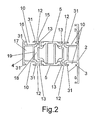
- FIG. 2 shows a preferred exemplary embodiment of the hollow profile for the frame construction according to the invention.
- the outer shell 3 and the inner shell 4 are divided by webs 19 into two hollow chambers 17, 18.
- the arrangement of the system grooves 10 and the locking grooves 12 including the webs 13 are arranged in mirror image to each other.
- each system groove 10 is separated by a web 11 of the immediately adjacent locking groove 12.
- the figure clearly shows that the system grooves 10 are undercut by two webs 31.
- the retaining strip 6 engage behind both webs, so that it is securely locked even at a high load.
- each locking groove 12 could also be undercut by two webs. However, if a minimum depth of the profile is desired, only by the web 13, the undercut should be formed. Furthermore, the figure shows that the depths of the locking grooves 12 are less than that of the System grooves 10. This can be in the locking grooves 12 set profiles with relatively small cross-sections.
- the profile can be regarded as capable of system with a correspondingly wide range of applications.
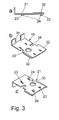
- FIGS. 3a-3c show a holder 14, which consists of two angle elements, wherein, for reasons of simplified illustration, only the first angle element 21 which can be fixed to the frame spar is shown. It contains at one end an angled web which engages around the surface element 7 on the outside. The opposite region is provided at the longitudinal edges with offsets 32, so that this area is at a distance from the associated surface of the frame Holmes.
- the second angle element not shown, is provided with correspondingly shaped guide pockets, so that the first angle element forms a guide element.
- the frame spar associated leg is provided with four locking webs 23, 24, wherein the diagonally opposite locking webs 23 are rectilinear and the likewise diagonally opposite locking webs 24 are formed as angle webs.
- latching webs 23, 24 can be seen in particular from FIG. 3c.
- recesses 34 and a bore 33 are provided for reducing the cross-section.
- the tabs embracing the surface element 7 are identified by the reference numeral 35.
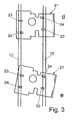
- Figures 3d and 3e show the introduction of the first angle element 21 in the locking grooves 12. Thereafter, the angle element 21 is first brought into such a position to the locking grooves 12 that the longitudinal edges of the angle element 21 are inclined to the locking grooves 12. The locking webs 23, 24 are then within the locking grooves 12. By a rotation in the counterclockwise direction, the angled end portions of the locking webs 24 engage under the webs 13, so that the angle element 21 is held non-positively and / or positively.
- FIG. 4 shows an integral angle element 36, which is designed to encompass the two sides of the surface element 7.
- the angle element 36 is at the Frame side facing the frame with two parallel and spaced apart locking webs 37, 38 provided, which are formed by U-shaped cuts of the frame spar facing leg. For this purpose, they are arcuately deformed, but twisted in opposite directions, so that the outer free edges of the locking webs 37, 38 although parallel and spaced apart, but that they are inclined to the longitudinal edges of the angle member 36.
- the angle element 36 can therefore first be brought in accordance with the figure 3e in an inclined position to the locking grooves 12, wherein the locking webs 37, 38 immerse it.
- the angle element 36 is then positively and / or positively fixed.
- the outer angled end region (tabs 35) is then assigned to the outer surface of the surface element 7. So that the surface element 7 is also held inside, the angle element 36 is provided with a U-shaped notch 39, from which a tab 41 along a bending line 40 can be erected, so that the tab 41 formed by the U-shaped notch 41, the surface element 7 secures from the inside.
- the raising of the tab 41 takes place after the insertion of the surface element 7 in the device. 1
- the invention is not limited to the illustrated embodiment.
- locking grooves 12 are arranged directly adjacent to these grooves 10 to receive other functional parts of a frame structure form-fitting and / or non-positively. It is significant that no screws or similar fasteners must be used to determine these functional parts.
Landscapes
- Engineering & Computer Science (AREA)
- Civil Engineering (AREA)
- Structural Engineering (AREA)
- Mutual Connection Of Rods And Tubes (AREA)
- Building Environments (AREA)
- Securing Of Glass Panes Or The Like (AREA)
Applications Claiming Priority (1)
| Application Number | Priority Date | Filing Date | Title |
|---|---|---|---|
| DE202006004607U DE202006004607U1 (de) | 2006-03-21 | 2006-03-21 | Rahmenkonstruktion für ein aus Rahmenholmen zusammengesetztes Bauelement |
Publications (3)
| Publication Number | Publication Date |
|---|---|
| EP1840314A2 true EP1840314A2 (fr) | 2007-10-03 |
| EP1840314A3 EP1840314A3 (fr) | 2014-03-12 |
| EP1840314B1 EP1840314B1 (fr) | 2016-10-19 |
Family
ID=36591152
Family Applications (1)
| Application Number | Title | Priority Date | Filing Date |
|---|---|---|---|
| EP07104323.6A Active EP1840314B1 (fr) | 2006-03-21 | 2007-03-16 | Composant coupe-feu |
Country Status (3)
| Country | Link |
|---|---|
| EP (1) | EP1840314B1 (fr) |
| DE (1) | DE202006004607U1 (fr) |
| PL (1) | PL1840314T3 (fr) |
Cited By (1)
| Publication number | Priority date | Publication date | Assignee | Title |
|---|---|---|---|---|
| DE102016121068A1 (de) | 2016-02-29 | 2017-08-31 | SCHÜCO International KG | Verbundprofil für eine Tür, ein Fenster oder ein Fassadenelement sowie Verfahren zur Herstellung des Verbundprofils |
Families Citing this family (4)
| Publication number | Priority date | Publication date | Assignee | Title |
|---|---|---|---|---|
| DE102008022893A1 (de) * | 2008-05-08 | 2009-11-19 | Hydro Aluminium As | Tür, Fenster oder dergleichen in wärmegedämmter Ausführung |
| DE202010012323U1 (de) * | 2010-09-08 | 2011-12-14 | Raico Bautechnik Gmbh | Blendrahmenprofil für Tür-, Fenster- oder Fassadenkonstruktionen |
| DE202010008621U1 (de) * | 2010-09-24 | 2011-10-14 | Heroal - Johann Henkenjohann Gmbh & Co. Kg | Leichtmetallprofil für Fassaden, Fenster, Türen o.dgl. |
| DE102019133839A1 (de) * | 2019-12-10 | 2021-06-10 | SCHÜCO International KG | Bauelement in Brandschutzausführung und Verfahren zur Montage eines Bauelementes |
Family Cites Families (10)
| Publication number | Priority date | Publication date | Assignee | Title |
|---|---|---|---|---|
| DE1400905A1 (de) | 1963-10-17 | 1969-06-26 | Schuermann & Co Heinz | Halter zur toleranzausgleichenden Befestigung von Deckelprofilen,Wandverkleidungs- und sonstigen Bauelementen auf Rahmen,Waenden,Fussboeden od.dgl. |
| NL9401613A (nl) | 1994-09-30 | 1996-05-01 | Reynolds Aluminium Bv | Brandwerend, aluminium kozijn. |
| DE19630468C1 (de) | 1996-07-27 | 1997-09-18 | Novoferm Gmbh | Vorrichtung zur Befestigung einer Scheibe in einer Türblattaussparung |
| GB9705410D0 (en) | 1997-03-15 | 1997-04-30 | Taylor Graham C | A retaining device for a glazed unit and a glazed unit including such a retaining device |
| SE512278C2 (sv) | 1997-12-19 | 2000-02-21 | Sapa Ab | Brandhärdigt byggelement |
| GB0011308D0 (en) * | 2000-05-10 | 2000-06-28 | Harrison Keith A | A security device |
| BE1014372A3 (nl) * | 2001-09-18 | 2003-09-02 | Reynaers Aluminium Nv | Brandwerend kozijn-paneel samenstel. |
| FI113077B (fi) | 2002-01-09 | 2004-02-27 | Purso Oy | Rakennuselementti |
| PL208873B1 (pl) | 2002-06-20 | 2011-06-30 | Metalplast Bielsko Społka Akcyjna | Zestaw kształtowników oraz elementów ościeżnicy i skrzydła w konstrukcji ognioodpornej |
| DE102004008414A1 (de) | 2004-02-20 | 2005-09-01 | Ingenieurbüro Dr.-Ing. Harald Schulz | Profilrahmenkonstruktion |
-
2006
- 2006-03-21 DE DE202006004607U patent/DE202006004607U1/de not_active Expired - Lifetime
-
2007
- 2007-03-16 EP EP07104323.6A patent/EP1840314B1/fr active Active
- 2007-03-16 PL PL07104323T patent/PL1840314T3/pl unknown
Cited By (1)
| Publication number | Priority date | Publication date | Assignee | Title |
|---|---|---|---|---|
| DE102016121068A1 (de) | 2016-02-29 | 2017-08-31 | SCHÜCO International KG | Verbundprofil für eine Tür, ein Fenster oder ein Fassadenelement sowie Verfahren zur Herstellung des Verbundprofils |
Also Published As
| Publication number | Publication date |
|---|---|
| PL1840314T3 (pl) | 2017-03-31 |
| EP1840314B1 (fr) | 2016-10-19 |
| EP1840314A3 (fr) | 2014-03-12 |
| DE202006004607U1 (de) | 2006-06-01 |
Similar Documents
| Publication | Publication Date | Title |
|---|---|---|
| EP1352134B1 (fr) | Construction a traverses et montants | |
| EP0136431B1 (fr) | Ossature en profilés | |
| EP3196396B1 (fr) | Élément de construction dans une construction anti-feu | |
| EP1840314B1 (fr) | Composant coupe-feu | |
| DE3838957C2 (fr) | ||
| EP0892138B1 (fr) | Ferrure avec une têtière pour une porte ou une fenêtre | |
| EP1764447A2 (fr) | Dispositif pour joint d'about pour façades bois/aluminium | |
| EP0127030B1 (fr) | Assemblage angulaire | |
| EP1323936A2 (fr) | Rail oblong | |
| EP0246509B1 (fr) | Tableau d'information avec dispositif de fixation | |
| EP2088337A2 (fr) | Profilé et système de profilés | |
| DE20019594U1 (de) | Justiervorrichtung eines Rahmens | |
| EP4365399B1 (fr) | Raccord d'angle | |
| EP2708693B1 (fr) | Cadre de battant ouvrant-coulissant | |
| EP3889384A1 (fr) | Profilé extrudé de section creuse de fenêtre ou de porte, système doté d'un tel profilé de section creuse et cadre fabriqué à partir de celui-ci | |
| EP0806338B1 (fr) | Liaison pour profilés | |
| EP1798186B1 (fr) | Cabine d'ascenseur et méthode de montage de panneaux d'une parroi de cabine | |
| DE10101318A1 (de) | Vorrichtung zum verspannenden Verbinden von zueinander beabstandeten Bauteilen | |
| EP1635075B1 (fr) | Dispositif de connection | |
| EP1186723B1 (fr) | Dispositif de fixation pour une façade avec montants et traverses | |
| EP0623530A1 (fr) | Système de convoyeur aérien avec un set de profilés de montage | |
| DE102013100308A1 (de) | Riegelstangenbeschlag für ein Fenster oder eine Tür | |
| EP2186959A2 (fr) | Connexion en T entre un poteau profilé et une traverse profilée | |
| EP1469157B1 (fr) | Profil de verrouillage | |
| EP1826331A2 (fr) | Aide au montage et construction de poteau traverse |
Legal Events
| Date | Code | Title | Description |
|---|---|---|---|
| PUAI | Public reference made under article 153(3) epc to a published international application that has entered the european phase |
Free format text: ORIGINAL CODE: 0009012 |
|
| AK | Designated contracting states |
Kind code of ref document: A2 Designated state(s): AT BE BG CH CY CZ DE DK EE ES FI FR GB GR HU IE IS IT LI LT LU LV MC MT NL PL PT RO SE SI SK TR |
|
| AX | Request for extension of the european patent |
Extension state: AL BA HR MK YU |
|
| PUAL | Search report despatched |
Free format text: ORIGINAL CODE: 0009013 |
|
| AK | Designated contracting states |
Kind code of ref document: A3 Designated state(s): AT BE BG CH CY CZ DE DK EE ES FI FR GB GR HU IE IS IT LI LT LU LV MC MT NL PL PT RO SE SI SK TR |
|
| AX | Request for extension of the european patent |
Extension state: AL BA HR MK RS |
|
| RIC1 | Information provided on ipc code assigned before grant |
Ipc: E06B 3/263 20060101AFI20140203BHEP |
|
| 17P | Request for examination filed |
Effective date: 20140911 |
|
| RBV | Designated contracting states (corrected) |
Designated state(s): AT BE BG CH CY CZ DE DK EE ES FI FR GB GR HU IE IS IT LI LT LU LV MC MT NL PL PT RO SE SI SK TR |
|
| AKX | Designation fees paid |
Designated state(s): AT BE BG CH CY CZ DE DK EE ES FI FR GB GR HU IE IS IT LI LT LU LV MC MT NL PL PT RO SE SI SK TR |
|
| GRAP | Despatch of communication of intention to grant a patent |
Free format text: ORIGINAL CODE: EPIDOSNIGR1 |
|
| INTG | Intention to grant announced |
Effective date: 20160601 |
|
| GRAS | Grant fee paid |
Free format text: ORIGINAL CODE: EPIDOSNIGR3 |
|
| GRAA | (expected) grant |
Free format text: ORIGINAL CODE: 0009210 |
|
| AK | Designated contracting states |
Kind code of ref document: B1 Designated state(s): AT BE BG CH CY CZ DE DK EE ES FI FR GB GR HU IE IS IT LI LT LU LV MC MT NL PL PT RO SE SI SK TR |
|
| REG | Reference to a national code |
Ref country code: GB Ref legal event code: FG4D Free format text: NOT ENGLISH |
|
| REG | Reference to a national code |
Ref country code: CH Ref legal event code: EP |
|
| REG | Reference to a national code |
Ref country code: AT Ref legal event code: REF Ref document number: 838510 Country of ref document: AT Kind code of ref document: T Effective date: 20161115 |
|
| REG | Reference to a national code |
Ref country code: IE Ref legal event code: FG4D Free format text: LANGUAGE OF EP DOCUMENT: GERMAN |
|
| REG | Reference to a national code |
Ref country code: DE Ref legal event code: R096 Ref document number: 502007015192 Country of ref document: DE |
|
| REG | Reference to a national code |
Ref country code: CH Ref legal event code: NV Representative=s name: ISLER AND PEDRAZZINI AG, CH |
|
| REG | Reference to a national code |
Ref country code: NL Ref legal event code: FP |
|
| REG | Reference to a national code |
Ref country code: SE Ref legal event code: TRGR |
|
| REG | Reference to a national code |
Ref country code: LT Ref legal event code: MG4D |
|
| PG25 | Lapsed in a contracting state [announced via postgrant information from national office to epo] |
Ref country code: LV Free format text: LAPSE BECAUSE OF FAILURE TO SUBMIT A TRANSLATION OF THE DESCRIPTION OR TO PAY THE FEE WITHIN THE PRESCRIBED TIME-LIMIT Effective date: 20161019 |
|
| REG | Reference to a national code |
Ref country code: FR Ref legal event code: PLFP Year of fee payment: 11 |
|
| PG25 | Lapsed in a contracting state [announced via postgrant information from national office to epo] |
Ref country code: GR Free format text: LAPSE BECAUSE OF FAILURE TO SUBMIT A TRANSLATION OF THE DESCRIPTION OR TO PAY THE FEE WITHIN THE PRESCRIBED TIME-LIMIT Effective date: 20170120 Ref country code: LT Free format text: LAPSE BECAUSE OF FAILURE TO SUBMIT A TRANSLATION OF THE DESCRIPTION OR TO PAY THE FEE WITHIN THE PRESCRIBED TIME-LIMIT Effective date: 20161019 |
|
| PG25 | Lapsed in a contracting state [announced via postgrant information from national office to epo] |
Ref country code: ES Free format text: LAPSE BECAUSE OF FAILURE TO SUBMIT A TRANSLATION OF THE DESCRIPTION OR TO PAY THE FEE WITHIN THE PRESCRIBED TIME-LIMIT Effective date: 20161019 Ref country code: IS Free format text: LAPSE BECAUSE OF FAILURE TO SUBMIT A TRANSLATION OF THE DESCRIPTION OR TO PAY THE FEE WITHIN THE PRESCRIBED TIME-LIMIT Effective date: 20170219 Ref country code: PT Free format text: LAPSE BECAUSE OF FAILURE TO SUBMIT A TRANSLATION OF THE DESCRIPTION OR TO PAY THE FEE WITHIN THE PRESCRIBED TIME-LIMIT Effective date: 20170220 |
|
| REG | Reference to a national code |
Ref country code: DE Ref legal event code: R026 Ref document number: 502007015192 Country of ref document: DE |
|
| PLBI | Opposition filed |
Free format text: ORIGINAL CODE: 0009260 |
|
| PG25 | Lapsed in a contracting state [announced via postgrant information from national office to epo] |
Ref country code: CZ Free format text: LAPSE BECAUSE OF FAILURE TO SUBMIT A TRANSLATION OF THE DESCRIPTION OR TO PAY THE FEE WITHIN THE PRESCRIBED TIME-LIMIT Effective date: 20161019 Ref country code: EE Free format text: LAPSE BECAUSE OF FAILURE TO SUBMIT A TRANSLATION OF THE DESCRIPTION OR TO PAY THE FEE WITHIN THE PRESCRIBED TIME-LIMIT Effective date: 20161019 Ref country code: RO Free format text: LAPSE BECAUSE OF FAILURE TO SUBMIT A TRANSLATION OF THE DESCRIPTION OR TO PAY THE FEE WITHIN THE PRESCRIBED TIME-LIMIT Effective date: 20161019 Ref country code: SK Free format text: LAPSE BECAUSE OF FAILURE TO SUBMIT A TRANSLATION OF THE DESCRIPTION OR TO PAY THE FEE WITHIN THE PRESCRIBED TIME-LIMIT Effective date: 20161019 Ref country code: DK Free format text: LAPSE BECAUSE OF FAILURE TO SUBMIT A TRANSLATION OF THE DESCRIPTION OR TO PAY THE FEE WITHIN THE PRESCRIBED TIME-LIMIT Effective date: 20161019 |
|
| PLAX | Notice of opposition and request to file observation + time limit sent |
Free format text: ORIGINAL CODE: EPIDOSNOBS2 |
|
| 26 | Opposition filed |
Opponent name: HUECK GMBH & CO. KG Effective date: 20170719 |
|
| PG25 | Lapsed in a contracting state [announced via postgrant information from national office to epo] |
Ref country code: BG Free format text: LAPSE BECAUSE OF FAILURE TO SUBMIT A TRANSLATION OF THE DESCRIPTION OR TO PAY THE FEE WITHIN THE PRESCRIBED TIME-LIMIT Effective date: 20170119 |
|
| PLAB | Opposition data, opponent's data or that of the opponent's representative modified |
Free format text: ORIGINAL CODE: 0009299OPPO |
|
| PG25 | Lapsed in a contracting state [announced via postgrant information from national office to epo] |
Ref country code: SI Free format text: LAPSE BECAUSE OF FAILURE TO SUBMIT A TRANSLATION OF THE DESCRIPTION OR TO PAY THE FEE WITHIN THE PRESCRIBED TIME-LIMIT Effective date: 20161019 Ref country code: MC Free format text: LAPSE BECAUSE OF FAILURE TO SUBMIT A TRANSLATION OF THE DESCRIPTION OR TO PAY THE FEE WITHIN THE PRESCRIBED TIME-LIMIT Effective date: 20161019 |
|
| PLBB | Reply of patent proprietor to notice(s) of opposition received |
Free format text: ORIGINAL CODE: EPIDOSNOBS3 |
|
| R26 | Opposition filed (corrected) |
Opponent name: HUECK GMBH & CO. KG Effective date: 20170719 |
|
| REG | Reference to a national code |
Ref country code: IE Ref legal event code: MM4A |
|
| PG25 | Lapsed in a contracting state [announced via postgrant information from national office to epo] |
Ref country code: LU Free format text: LAPSE BECAUSE OF NON-PAYMENT OF DUE FEES Effective date: 20170316 |
|
| PG25 | Lapsed in a contracting state [announced via postgrant information from national office to epo] |
Ref country code: IE Free format text: LAPSE BECAUSE OF NON-PAYMENT OF DUE FEES Effective date: 20170316 |
|
| REG | Reference to a national code |
Ref country code: FR Ref legal event code: PLFP Year of fee payment: 12 |
|
| PLAB | Opposition data, opponent's data or that of the opponent's representative modified |
Free format text: ORIGINAL CODE: 0009299OPPO |
|
| R26 | Opposition filed (corrected) |
Opponent name: HUECK GMBH & CO. KG Effective date: 20170719 |
|
| PG25 | Lapsed in a contracting state [announced via postgrant information from national office to epo] |
Ref country code: MT Free format text: LAPSE BECAUSE OF FAILURE TO SUBMIT A TRANSLATION OF THE DESCRIPTION OR TO PAY THE FEE WITHIN THE PRESCRIBED TIME-LIMIT Effective date: 20161019 |
|
| PLAY | Examination report in opposition despatched + time limit |
Free format text: ORIGINAL CODE: EPIDOSNORE2 |
|
| PLBC | Reply to examination report in opposition received |
Free format text: ORIGINAL CODE: EPIDOSNORE3 |
|
| REG | Reference to a national code |
Ref country code: CH Ref legal event code: PK Free format text: TITEL |
|
| APAH | Appeal reference modified |
Free format text: ORIGINAL CODE: EPIDOSCREFNO |
|
| APBM | Appeal reference recorded |
Free format text: ORIGINAL CODE: EPIDOSNREFNO |
|
| APBP | Date of receipt of notice of appeal recorded |
Free format text: ORIGINAL CODE: EPIDOSNNOA2O |
|
| PLAB | Opposition data, opponent's data or that of the opponent's representative modified |
Free format text: ORIGINAL CODE: 0009299OPPO |
|
| PG25 | Lapsed in a contracting state [announced via postgrant information from national office to epo] |
Ref country code: HU Free format text: LAPSE BECAUSE OF FAILURE TO SUBMIT A TRANSLATION OF THE DESCRIPTION OR TO PAY THE FEE WITHIN THE PRESCRIBED TIME-LIMIT; INVALID AB INITIO Effective date: 20070316 |
|
| R26 | Opposition filed (corrected) |
Opponent name: HUECK GMBH & CO. KG Effective date: 20170719 |
|
| APBQ | Date of receipt of statement of grounds of appeal recorded |
Free format text: ORIGINAL CODE: EPIDOSNNOA3O |
|
| PG25 | Lapsed in a contracting state [announced via postgrant information from national office to epo] |
Ref country code: CY Free format text: LAPSE BECAUSE OF NON-PAYMENT OF DUE FEES Effective date: 20161019 |
|
| PG25 | Lapsed in a contracting state [announced via postgrant information from national office to epo] |
Ref country code: TR Free format text: LAPSE BECAUSE OF FAILURE TO SUBMIT A TRANSLATION OF THE DESCRIPTION OR TO PAY THE FEE WITHIN THE PRESCRIBED TIME-LIMIT Effective date: 20161019 |
|
| PGFP | Annual fee paid to national office [announced via postgrant information from national office to epo] |
Ref country code: SE Payment date: 20200227 Year of fee payment: 14 Ref country code: FI Payment date: 20200319 Year of fee payment: 14 Ref country code: NL Payment date: 20200226 Year of fee payment: 14 Ref country code: AT Payment date: 20200226 Year of fee payment: 14 |
|
| PLBP | Opposition withdrawn |
Free format text: ORIGINAL CODE: 0009264 |
|
| REG | Reference to a national code |
Ref country code: FI Ref legal event code: MAE |
|
| PG25 | Lapsed in a contracting state [announced via postgrant information from national office to epo] |
Ref country code: FI Free format text: LAPSE BECAUSE OF NON-PAYMENT OF DUE FEES Effective date: 20210316 |
|
| REG | Reference to a national code |
Ref country code: NL Ref legal event code: MM Effective date: 20210401 |
|
| REG | Reference to a national code |
Ref country code: AT Ref legal event code: MM01 Ref document number: 838510 Country of ref document: AT Kind code of ref document: T Effective date: 20210316 |
|
| PG25 | Lapsed in a contracting state [announced via postgrant information from national office to epo] |
Ref country code: AT Free format text: LAPSE BECAUSE OF NON-PAYMENT OF DUE FEES Effective date: 20210316 Ref country code: NL Free format text: LAPSE BECAUSE OF NON-PAYMENT OF DUE FEES Effective date: 20210401 Ref country code: SE Free format text: LAPSE BECAUSE OF NON-PAYMENT OF DUE FEES Effective date: 20210317 |
|
| PGFP | Annual fee paid to national office [announced via postgrant information from national office to epo] |
Ref country code: GB Payment date: 20220310 Year of fee payment: 16 Ref country code: CH Payment date: 20220310 Year of fee payment: 16 |
|
| PGFP | Annual fee paid to national office [announced via postgrant information from national office to epo] |
Ref country code: IT Payment date: 20220331 Year of fee payment: 16 |
|
| PLAB | Opposition data, opponent's data or that of the opponent's representative modified |
Free format text: ORIGINAL CODE: 0009299OPPO |
|
| P01 | Opt-out of the competence of the unified patent court (upc) registered |
Effective date: 20230813 |
|
| REG | Reference to a national code |
Ref country code: CH Ref legal event code: PL |
|
| APBU | Appeal procedure closed |
Free format text: ORIGINAL CODE: EPIDOSNNOA9O |
|
| GBPC | Gb: european patent ceased through non-payment of renewal fee |
Effective date: 20230316 |
|
| REG | Reference to a national code |
Ref country code: DE Ref legal event code: R100 Ref document number: 502007015192 Country of ref document: DE |
|
| PLCK | Communication despatched that opposition was rejected |
Free format text: ORIGINAL CODE: EPIDOSNREJ1 |
|
| STAA | Information on the status of an ep patent application or granted ep patent |
Free format text: STATUS: OPPOSITION REJECTED |
|
| PLBN | Opposition rejected |
Free format text: ORIGINAL CODE: 0009273 |
|
| 27O | Opposition rejected |
Effective date: 20231211 |
|
| PG25 | Lapsed in a contracting state [announced via postgrant information from national office to epo] |
Ref country code: GB Free format text: LAPSE BECAUSE OF NON-PAYMENT OF DUE FEES Effective date: 20230316 |
|
| PG25 | Lapsed in a contracting state [announced via postgrant information from national office to epo] |
Ref country code: LI Free format text: LAPSE BECAUSE OF NON-PAYMENT OF DUE FEES Effective date: 20230331 Ref country code: GB Free format text: LAPSE BECAUSE OF NON-PAYMENT OF DUE FEES Effective date: 20230316 Ref country code: CH Free format text: LAPSE BECAUSE OF NON-PAYMENT OF DUE FEES Effective date: 20230331 |
|
| PG25 | Lapsed in a contracting state [announced via postgrant information from national office to epo] |
Ref country code: IT Free format text: LAPSE BECAUSE OF NON-PAYMENT OF DUE FEES Effective date: 20230316 |
|
| PGFP | Annual fee paid to national office [announced via postgrant information from national office to epo] |
Ref country code: DE Payment date: 20260305 Year of fee payment: 20 |
|
| PGFP | Annual fee paid to national office [announced via postgrant information from national office to epo] |
Ref country code: BE Payment date: 20260306 Year of fee payment: 20 |
|
| PGFP | Annual fee paid to national office [announced via postgrant information from national office to epo] |
Ref country code: FR Payment date: 20260305 Year of fee payment: 20 |
|
| PGFP | Annual fee paid to national office [announced via postgrant information from national office to epo] |
Ref country code: PL Payment date: 20260306 Year of fee payment: 20 |