EP4571176A1 - Système d'éclairage pour phare de véhicule - Google Patents
Système d'éclairage pour phare de véhicule Download PDFInfo
- Publication number
- EP4571176A1 EP4571176A1 EP23215632.3A EP23215632A EP4571176A1 EP 4571176 A1 EP4571176 A1 EP 4571176A1 EP 23215632 A EP23215632 A EP 23215632A EP 4571176 A1 EP4571176 A1 EP 4571176A1
- Authority
- EP
- European Patent Office
- Prior art keywords
- light
- light guide
- illuminant
- lighting system
- guide channel
- Prior art date
- Legal status (The legal status is an assumption and is not a legal conclusion. Google has not performed a legal analysis and makes no representation as to the accuracy of the status listed.)
- Pending
Links
Images

Classifications
-
- F—MECHANICAL ENGINEERING; LIGHTING; HEATING; WEAPONS; BLASTING
- F21—LIGHTING
- F21S—NON-PORTABLE LIGHTING DEVICES; SYSTEMS THEREOF; VEHICLE LIGHTING DEVICES SPECIALLY ADAPTED FOR VEHICLE EXTERIORS
- F21S41/00—Illuminating devices specially adapted for vehicle exteriors, e.g. headlamps
- F21S41/10—Illuminating devices specially adapted for vehicle exteriors, e.g. headlamps characterised by the light source
- F21S41/14—Illuminating devices specially adapted for vehicle exteriors, e.g. headlamps characterised by the light source characterised by the type of light source
- F21S41/141—Light emitting diodes [LED]
- F21S41/151—Light emitting diodes [LED] arranged in one or more lines
-
- B—PERFORMING OPERATIONS; TRANSPORTING
- B60—VEHICLES IN GENERAL
- B60Q—ARRANGEMENT OF SIGNALLING OR LIGHTING DEVICES, THE MOUNTING OR SUPPORTING THEREOF OR CIRCUITS THEREFOR, FOR VEHICLES IN GENERAL
- B60Q1/00—Arrangement of optical signalling or lighting devices, the mounting or supporting thereof or circuits therefor
- B60Q1/0029—Spatial arrangement
- B60Q1/0041—Spatial arrangement of several lamps in relation to each other
- B60Q1/0058—Stacked, i.e. one lamp located behind the other in the optical axis direction
-
- F—MECHANICAL ENGINEERING; LIGHTING; HEATING; WEAPONS; BLASTING
- F21—LIGHTING
- F21S—NON-PORTABLE LIGHTING DEVICES; SYSTEMS THEREOF; VEHICLE LIGHTING DEVICES SPECIALLY ADAPTED FOR VEHICLE EXTERIORS
- F21S41/00—Illuminating devices specially adapted for vehicle exteriors, e.g. headlamps
-
- B—PERFORMING OPERATIONS; TRANSPORTING
- B60—VEHICLES IN GENERAL
- B60Q—ARRANGEMENT OF SIGNALLING OR LIGHTING DEVICES, THE MOUNTING OR SUPPORTING THEREOF OR CIRCUITS THEREFOR, FOR VEHICLES IN GENERAL
- B60Q1/00—Arrangement of optical signalling or lighting devices, the mounting or supporting thereof or circuits therefor
- B60Q1/26—Arrangement of optical signalling or lighting devices, the mounting or supporting thereof or circuits therefor the devices being primarily intended to indicate the vehicle, or parts thereof, or to give signals, to other traffic
- B60Q1/2607—Arrangement of optical signalling or lighting devices, the mounting or supporting thereof or circuits therefor the devices being primarily intended to indicate the vehicle, or parts thereof, or to give signals, to other traffic comprising at least two indicating lamps
-
- B—PERFORMING OPERATIONS; TRANSPORTING
- B60—VEHICLES IN GENERAL
- B60Q—ARRANGEMENT OF SIGNALLING OR LIGHTING DEVICES, THE MOUNTING OR SUPPORTING THEREOF OR CIRCUITS THEREFOR, FOR VEHICLES IN GENERAL
- B60Q1/00—Arrangement of optical signalling or lighting devices, the mounting or supporting thereof or circuits therefor
- B60Q1/26—Arrangement of optical signalling or lighting devices, the mounting or supporting thereof or circuits therefor the devices being primarily intended to indicate the vehicle, or parts thereof, or to give signals, to other traffic
- B60Q1/34—Arrangement of optical signalling or lighting devices, the mounting or supporting thereof or circuits therefor the devices being primarily intended to indicate the vehicle, or parts thereof, or to give signals, to other traffic for indicating change of drive direction
- B60Q1/38—Arrangement of optical signalling or lighting devices, the mounting or supporting thereof or circuits therefor the devices being primarily intended to indicate the vehicle, or parts thereof, or to give signals, to other traffic for indicating change of drive direction using immovably-mounted light sources, e.g. fixed flashing lamps
- B60Q1/381—Arrangement of optical signalling or lighting devices, the mounting or supporting thereof or circuits therefor the devices being primarily intended to indicate the vehicle, or parts thereof, or to give signals, to other traffic for indicating change of drive direction using immovably-mounted light sources, e.g. fixed flashing lamps with several light sources activated in sequence, e.g. to create a sweep effect
-
- F—MECHANICAL ENGINEERING; LIGHTING; HEATING; WEAPONS; BLASTING
- F21—LIGHTING
- F21S—NON-PORTABLE LIGHTING DEVICES; SYSTEMS THEREOF; VEHICLE LIGHTING DEVICES SPECIALLY ADAPTED FOR VEHICLE EXTERIORS
- F21S41/00—Illuminating devices specially adapted for vehicle exteriors, e.g. headlamps
- F21S41/10—Illuminating devices specially adapted for vehicle exteriors, e.g. headlamps characterised by the light source
- F21S41/19—Attachment of light sources or lamp holders
-
- F—MECHANICAL ENGINEERING; LIGHTING; HEATING; WEAPONS; BLASTING
- F21—LIGHTING
- F21S—NON-PORTABLE LIGHTING DEVICES; SYSTEMS THEREOF; VEHICLE LIGHTING DEVICES SPECIALLY ADAPTED FOR VEHICLE EXTERIORS
- F21S41/00—Illuminating devices specially adapted for vehicle exteriors, e.g. headlamps
- F21S41/20—Illuminating devices specially adapted for vehicle exteriors, e.g. headlamps characterised by refractors, transparent cover plates, light guides or filters
- F21S41/24—Light guides
-
- F—MECHANICAL ENGINEERING; LIGHTING; HEATING; WEAPONS; BLASTING
- F21—LIGHTING
- F21S—NON-PORTABLE LIGHTING DEVICES; SYSTEMS THEREOF; VEHICLE LIGHTING DEVICES SPECIALLY ADAPTED FOR VEHICLE EXTERIORS
- F21S41/00—Illuminating devices specially adapted for vehicle exteriors, e.g. headlamps
- F21S41/60—Illuminating devices specially adapted for vehicle exteriors, e.g. headlamps characterised by a variable light distribution
- F21S41/65—Illuminating devices specially adapted for vehicle exteriors, e.g. headlamps characterised by a variable light distribution by acting on light sources
- F21S41/663—Illuminating devices specially adapted for vehicle exteriors, e.g. headlamps characterised by a variable light distribution by acting on light sources by switching light sources
-
- F—MECHANICAL ENGINEERING; LIGHTING; HEATING; WEAPONS; BLASTING
- F21—LIGHTING
- F21S—NON-PORTABLE LIGHTING DEVICES; SYSTEMS THEREOF; VEHICLE LIGHTING DEVICES SPECIALLY ADAPTED FOR VEHICLE EXTERIORS
- F21S43/00—Signalling devices specially adapted for vehicle exteriors, e.g. brake lamps, direction indicator lights or reversing lights
- F21S43/10—Signalling devices specially adapted for vehicle exteriors, e.g. brake lamps, direction indicator lights or reversing lights characterised by the light source
-
- F—MECHANICAL ENGINEERING; LIGHTING; HEATING; WEAPONS; BLASTING
- F21—LIGHTING
- F21S—NON-PORTABLE LIGHTING DEVICES; SYSTEMS THEREOF; VEHICLE LIGHTING DEVICES SPECIALLY ADAPTED FOR VEHICLE EXTERIORS
- F21S43/00—Signalling devices specially adapted for vehicle exteriors, e.g. brake lamps, direction indicator lights or reversing lights
- F21S43/10—Signalling devices specially adapted for vehicle exteriors, e.g. brake lamps, direction indicator lights or reversing lights characterised by the light source
- F21S43/13—Signalling devices specially adapted for vehicle exteriors, e.g. brake lamps, direction indicator lights or reversing lights characterised by the light source characterised by the type of light source
- F21S43/14—Light emitting diodes [LED]
-
- F—MECHANICAL ENGINEERING; LIGHTING; HEATING; WEAPONS; BLASTING
- F21—LIGHTING
- F21S—NON-PORTABLE LIGHTING DEVICES; SYSTEMS THEREOF; VEHICLE LIGHTING DEVICES SPECIALLY ADAPTED FOR VEHICLE EXTERIORS
- F21S43/00—Signalling devices specially adapted for vehicle exteriors, e.g. brake lamps, direction indicator lights or reversing lights
- F21S43/10—Signalling devices specially adapted for vehicle exteriors, e.g. brake lamps, direction indicator lights or reversing lights characterised by the light source
- F21S43/13—Signalling devices specially adapted for vehicle exteriors, e.g. brake lamps, direction indicator lights or reversing lights characterised by the light source characterised by the type of light source
- F21S43/15—Strips of light sources
-
- F—MECHANICAL ENGINEERING; LIGHTING; HEATING; WEAPONS; BLASTING
- F21—LIGHTING
- F21S—NON-PORTABLE LIGHTING DEVICES; SYSTEMS THEREOF; VEHICLE LIGHTING DEVICES SPECIALLY ADAPTED FOR VEHICLE EXTERIORS
- F21S43/00—Signalling devices specially adapted for vehicle exteriors, e.g. brake lamps, direction indicator lights or reversing lights
- F21S43/20—Signalling devices specially adapted for vehicle exteriors, e.g. brake lamps, direction indicator lights or reversing lights characterised by refractors, transparent cover plates, light guides or filters
- F21S43/235—Light guides
-
- F—MECHANICAL ENGINEERING; LIGHTING; HEATING; WEAPONS; BLASTING
- F21—LIGHTING
- F21S—NON-PORTABLE LIGHTING DEVICES; SYSTEMS THEREOF; VEHICLE LIGHTING DEVICES SPECIALLY ADAPTED FOR VEHICLE EXTERIORS
- F21S43/00—Signalling devices specially adapted for vehicle exteriors, e.g. brake lamps, direction indicator lights or reversing lights
- F21S43/20—Signalling devices specially adapted for vehicle exteriors, e.g. brake lamps, direction indicator lights or reversing lights characterised by refractors, transparent cover plates, light guides or filters
- F21S43/235—Light guides
- F21S43/236—Light guides characterised by the shape of the light guide
- F21S43/237—Light guides characterised by the shape of the light guide rod-shaped
-
- F—MECHANICAL ENGINEERING; LIGHTING; HEATING; WEAPONS; BLASTING
- F21—LIGHTING
- F21S—NON-PORTABLE LIGHTING DEVICES; SYSTEMS THEREOF; VEHICLE LIGHTING DEVICES SPECIALLY ADAPTED FOR VEHICLE EXTERIORS
- F21S43/00—Signalling devices specially adapted for vehicle exteriors, e.g. brake lamps, direction indicator lights or reversing lights
- F21S43/20—Signalling devices specially adapted for vehicle exteriors, e.g. brake lamps, direction indicator lights or reversing lights characterised by refractors, transparent cover plates, light guides or filters
- F21S43/235—Light guides
- F21S43/242—Light guides characterised by the emission area
- F21S43/245—Light guides characterised by the emission area emitting light from one or more of its major surfaces
-
- F—MECHANICAL ENGINEERING; LIGHTING; HEATING; WEAPONS; BLASTING
- F21—LIGHTING
- F21S—NON-PORTABLE LIGHTING DEVICES; SYSTEMS THEREOF; VEHICLE LIGHTING DEVICES SPECIALLY ADAPTED FOR VEHICLE EXTERIORS
- F21S43/00—Signalling devices specially adapted for vehicle exteriors, e.g. brake lamps, direction indicator lights or reversing lights
- F21S43/20—Signalling devices specially adapted for vehicle exteriors, e.g. brake lamps, direction indicator lights or reversing lights characterised by refractors, transparent cover plates, light guides or filters
- F21S43/235—Light guides
- F21S43/249—Light guides with two or more light sources being coupled into the light guide
-
- F—MECHANICAL ENGINEERING; LIGHTING; HEATING; WEAPONS; BLASTING
- F21—LIGHTING
- F21S—NON-PORTABLE LIGHTING DEVICES; SYSTEMS THEREOF; VEHICLE LIGHTING DEVICES SPECIALLY ADAPTED FOR VEHICLE EXTERIORS
- F21S43/00—Signalling devices specially adapted for vehicle exteriors, e.g. brake lamps, direction indicator lights or reversing lights
- F21S43/20—Signalling devices specially adapted for vehicle exteriors, e.g. brake lamps, direction indicator lights or reversing lights characterised by refractors, transparent cover plates, light guides or filters
- F21S43/2605—Refractors
- F21S43/2621—Refractors characterised by the properties of the light beam shaping surface
- F21S43/26241—Refractors characterised by the properties of the light beam shaping surface diffusing, scattering or spreading
-
- F—MECHANICAL ENGINEERING; LIGHTING; HEATING; WEAPONS; BLASTING
- F21—LIGHTING
- F21S—NON-PORTABLE LIGHTING DEVICES; SYSTEMS THEREOF; VEHICLE LIGHTING DEVICES SPECIALLY ADAPTED FOR VEHICLE EXTERIORS
- F21S43/00—Signalling devices specially adapted for vehicle exteriors, e.g. brake lamps, direction indicator lights or reversing lights
- F21S43/20—Signalling devices specially adapted for vehicle exteriors, e.g. brake lamps, direction indicator lights or reversing lights characterised by refractors, transparent cover plates, light guides or filters
- F21S43/2605—Refractors
- F21S43/2643—Refractors with several light entry surfaces for two or more light sources having distinct functions, at least one of them being signalling
-
- F—MECHANICAL ENGINEERING; LIGHTING; HEATING; WEAPONS; BLASTING
- F21—LIGHTING
- F21S—NON-PORTABLE LIGHTING DEVICES; SYSTEMS THEREOF; VEHICLE LIGHTING DEVICES SPECIALLY ADAPTED FOR VEHICLE EXTERIORS
- F21S43/00—Signalling devices specially adapted for vehicle exteriors, e.g. brake lamps, direction indicator lights or reversing lights
- F21S43/20—Signalling devices specially adapted for vehicle exteriors, e.g. brake lamps, direction indicator lights or reversing lights characterised by refractors, transparent cover plates, light guides or filters
- F21S43/27—Attachment thereof
-
- F—MECHANICAL ENGINEERING; LIGHTING; HEATING; WEAPONS; BLASTING
- F21—LIGHTING
- F21S—NON-PORTABLE LIGHTING DEVICES; SYSTEMS THEREOF; VEHICLE LIGHTING DEVICES SPECIALLY ADAPTED FOR VEHICLE EXTERIORS
- F21S43/00—Signalling devices specially adapted for vehicle exteriors, e.g. brake lamps, direction indicator lights or reversing lights
- F21S43/30—Signalling devices specially adapted for vehicle exteriors, e.g. brake lamps, direction indicator lights or reversing lights characterised by reflectors
- F21S43/31—Optical layout thereof
-
- F—MECHANICAL ENGINEERING; LIGHTING; HEATING; WEAPONS; BLASTING
- F21—LIGHTING
- F21S—NON-PORTABLE LIGHTING DEVICES; SYSTEMS THEREOF; VEHICLE LIGHTING DEVICES SPECIALLY ADAPTED FOR VEHICLE EXTERIORS
- F21S43/00—Signalling devices specially adapted for vehicle exteriors, e.g. brake lamps, direction indicator lights or reversing lights
- F21S43/30—Signalling devices specially adapted for vehicle exteriors, e.g. brake lamps, direction indicator lights or reversing lights characterised by reflectors
- F21S43/33—Signalling devices specially adapted for vehicle exteriors, e.g. brake lamps, direction indicator lights or reversing lights characterised by reflectors characterised by their material, surface treatment or coatings
- F21S43/332—Diffusing reflectors
-
- F—MECHANICAL ENGINEERING; LIGHTING; HEATING; WEAPONS; BLASTING
- F21—LIGHTING
- F21S—NON-PORTABLE LIGHTING DEVICES; SYSTEMS THEREOF; VEHICLE LIGHTING DEVICES SPECIALLY ADAPTED FOR VEHICLE EXTERIORS
- F21S43/00—Signalling devices specially adapted for vehicle exteriors, e.g. brake lamps, direction indicator lights or reversing lights
- F21S43/40—Signalling devices specially adapted for vehicle exteriors, e.g. brake lamps, direction indicator lights or reversing lights characterised by the combination of reflectors and refractors
- F21S43/401—Signalling devices specially adapted for vehicle exteriors, e.g. brake lamps, direction indicator lights or reversing lights characterised by the combination of reflectors and refractors the refractors and the reflectors being distinct parts
-
- B—PERFORMING OPERATIONS; TRANSPORTING
- B60—VEHICLES IN GENERAL
- B60Q—ARRANGEMENT OF SIGNALLING OR LIGHTING DEVICES, THE MOUNTING OR SUPPORTING THEREOF OR CIRCUITS THEREFOR, FOR VEHICLES IN GENERAL
- B60Q2400/00—Special features or arrangements of exterior signal lamps for vehicles
- B60Q2400/30—Daytime running lights [DRL], e.g. circuits or arrangements therefor
-
- F—MECHANICAL ENGINEERING; LIGHTING; HEATING; WEAPONS; BLASTING
- F21—LIGHTING
- F21W—INDEXING SCHEME ASSOCIATED WITH SUBCLASSES F21K, F21L, F21S and F21V, RELATING TO USES OR APPLICATIONS OF LIGHTING DEVICES OR SYSTEMS
- F21W2102/00—Exterior vehicle lighting devices for illuminating purposes
- F21W2102/10—Arrangement or contour of the emitted light
-
- F—MECHANICAL ENGINEERING; LIGHTING; HEATING; WEAPONS; BLASTING
- F21—LIGHTING
- F21W—INDEXING SCHEME ASSOCIATED WITH SUBCLASSES F21K, F21L, F21S and F21V, RELATING TO USES OR APPLICATIONS OF LIGHTING DEVICES OR SYSTEMS
- F21W2103/00—Exterior vehicle lighting devices for signalling purposes
- F21W2103/55—Daytime running lights [DRL]
-
- F—MECHANICAL ENGINEERING; LIGHTING; HEATING; WEAPONS; BLASTING
- F21—LIGHTING
- F21W—INDEXING SCHEME ASSOCIATED WITH SUBCLASSES F21K, F21L, F21S and F21V, RELATING TO USES OR APPLICATIONS OF LIGHTING DEVICES OR SYSTEMS
- F21W2105/00—Combinations of lighting devices covered by codes F21W2102/00 – F21W2104/00
-
- F—MECHANICAL ENGINEERING; LIGHTING; HEATING; WEAPONS; BLASTING
- F21—LIGHTING
- F21W—INDEXING SCHEME ASSOCIATED WITH SUBCLASSES F21K, F21L, F21S and F21V, RELATING TO USES OR APPLICATIONS OF LIGHTING DEVICES OR SYSTEMS
- F21W2107/00—Use or application of lighting devices on or in particular types of vehicles
- F21W2107/10—Use or application of lighting devices on or in particular types of vehicles for land vehicles
Definitions
- the invention further relates to a vehicle lamp, for example a motor vehicle headlight, or a vehicle, preferably a motor vehicle, comprising a lighting system.
- a vehicle lamp for example a motor vehicle headlight, or a vehicle, preferably a motor vehicle, comprising a lighting system.
- Lighting systems that use a light guide to emit light are known in the prior art.
- the light guide together with a light source, serves to generate a static (in the sense of non-animated or without an animation effect) lighting function.
- a dynamic, high-resolution lighting function which is intended to be generated in addition to or in addition to the static lighting function, is not provided for in light guide-based systems.
- a further or additional light module (or lighting device) is used to generate a dynamic, high-resolution lighting function.
- a static rear light of a motor vehicle can be generated with a first light module having a light guide, and a dynamic, animated direction indicator with a second light module having a plurality of LEDs.
- the object of the present invention is to alleviate or eliminate the disadvantages of the prior art.
- the invention therefore aims, in particular, to create a lighting system with which high-resolution, dynamic, and static lighting functions can be generated easily and with high homogeneity.
- the light from the second light source is broadened in the first plane by the light guide channel element (or when passing through the light guide channels of the light guide channel element) onto the second light coupling surface and is bundled in the second.
- This allows, on the one hand, a high quantity of light to reach the second light coupling surface and, on the other hand, the most homogeneous radiation behavior possible can be achieved between adjacent sections of the light coupling surface (which are illuminated by light from adjacent light guide channels).
- This allows a first, static light function to be generated with the first light source and the light guide, and simultaneously a second, high-resolution and/or dynamic light function to be generated with the second light source, which radiates radially through the light guide.
- the second light sources are preferably arranged along the entire axial longitudinal extent of the light guide.
- the light guide is illuminated axially with the light of the first illuminant and simultaneously radially with the light of the second illuminant.
- the wall has at least four side surfaces, wherein two side surfaces are opposite one another in pairs, wherein a first side surface pair, which is formed from two side surfaces which are arranged at a distance from one another along the axial longitudinal extent of the light guide, diverge from one another along the second light propagation direction, wherein a second side surface pair, which is formed from two side surfaces which are arranged at a distance from one another along a radial direction of the light guide which is orthogonal to the axial longitudinal extent, converge towards one another along the second light propagation direction.
- the lighting system has a cover plate which is arranged along the second light emission direction after the light guide channel element and preferably after the light guide, wherein the cover plate preferably has a holding section to which the light guide is fastened.
- the lighting system has a cover plate which is arranged along the second light emission direction after the light guide channel element and preferably after the light guide, wherein the cover plate has a region which is transparent to the light of the first illuminant and the second illuminant and which is surrounded by a region which is opaque to the light of the first illuminant and the second illuminant, wherein the cover plate is arranged in relation to the light guide channel element and the light guide in such a way that light which is coupled out of the light coupling-out section of the light guide preferably passes exclusively through the transparent region of the cover plate.
- the light sources are arranged on the light source carrier along an imaginary line and thus form a row of light sources, wherein the row of light sources preferably follows the axial longitudinal extent of the light guide.
- the optical fiber is designed to be substantially cylindrical, wherein the first light coupling section is formed on a base surface of the cylindrical optical fiber and the second light coupling section and the light coupling section are formed on a cylinder jacket, in particular on opposite sides of a cylinder jacket, of the cylindrical optical fiber.
- the light guide and the first light source are designed to generate a daytime running light.
- the light guide and the plurality of light sources of the second illuminant are designed to generate a, in particular dynamic, signal light, for example a direction indicator or a flashing light with a running light effect.
- light which is coupled into the light guide by the first illuminant propagates within the light guide by means of total reflection at the lateral surface along the longitudinal extent of the light guide.
- the first illuminant is arranged relative to the second illuminant such that the first light emission direction is oriented orthogonally to the second light emission direction.
- the light guide channel element is designed in such a way that light coupled out of the light guide channels illuminates the entire second light coupling region of the lateral surface, wherein the light guide channel element is preferably designed as a light guide aperture.
- first pair of side surfaces and/or the second pair of side surfaces have a surface designed to diffusely scatter light from the second illuminant, wherein preferably the first pair of side surfaces and/or the second pair of side surfaces is designed to have a diffusely scattering coating and/or to be matt white or opaque white, or wherein the first pair of side surfaces and/or the second pair of side surfaces is designed to be reflective, preferably diffusely, for light from the second illuminant, and in particular has a preferably diffusely reflective coating, for example a metallic coating.
- the light guide channel element is designed in such a way that light which is coupled out from two adjacent light guide channels impinges on the second light coupling section without overlap.
- light of the second illuminant coupled in via the partial regions of the second light coupling section overlaps with the light which is radially coupled into the light guide by the first illuminant via the first light coupling region, after coupling out via the light coupling section along the second light emission direction.
- the light guide channel element has a fastening section to which the light guide is fastened.
- the fastening section can be funnel-shaped or frustoconical, in particular the fastening section can be trapezoidal in a sectional plane oriented parallel to the second plane, or the fastening section can be trench-shaped along the axial longitudinal extent of the light guide.
- the light guide can lie within a tapered funnel opening of the fastening section or be held there.
- the fastening section can be arranged along the second light emission direction downstream of the light exit areas of the light guide channels, and preferably in front of a cover plate.
- a base (the longer Base side) of the trapezoidal fastening section is further away from (or facing away from) the second illuminant and the shorter base side of the trapezoidal fastening section opposite the base is closer to (or facing) the illuminant, wherein preferably the base of the trapezoidal fastening section is shorter than the diameter of the light guide.
- the wall delimiting a light guide channel delimits a cavity through which the light of the light source associated with the light guide channel passes.
- the cavity is free of optically active elements, for example one or more lenses, optical fibers or optical fibers.
- a vehicle lamp for example a motor vehicle headlight, or a vehicle comprising a lighting system may be provided.
- top For the purposes of this description, the terms “top”, “bottom”, “horizontal” and “vertical” are to be understood as indicating the orientation when the lighting system is arranged in the normal position of use after it has been installed in a motor vehicle or a motor vehicle headlamp.
- Fig. 1 shows an embodiment of a lighting system 1 for a vehicle lamp according to the invention, wherein the vehicle lamp is, for example, a Motor vehicle headlight, a component of a motor vehicle headlight, or a signal lamp for a motor vehicle.
- the vehicle lamp is, for example, a Motor vehicle headlight, a component of a motor vehicle headlight, or a signal lamp for a motor vehicle.
- Fig. 2 shows a top view of a section through the Fig. 1 shown lighting system, where the section is through a, in the plane of the page of Fig. 1 , horizontal cutting plane.
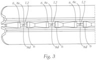
- Fig. 3 shows a rear view of the Fig. 1 lighting system shown.
- the lighting system 1 comprises a first illuminant L1, which is configured to emit light along a first light emission direction R1.
- the lighting system 1 further comprises a second illuminant L2, which has a plurality of individually controllable light sources 2.
- the individual light sources 2 are arranged spaced apart from one another on a light source carrier 3 (for example, a flexible printed circuit board) of the second illuminant L2 and are configured to emit light along a second light emission direction R2 (cf. Fig. 2 ), which is different from the first light emission direction R1.
- a light source carrier 3 for example, a flexible printed circuit board
- the first illuminant L1 is arranged relative to the second illuminant L2 such that the first light emission direction R1 is oriented orthogonally to the second light emission direction R2.
- the sectional plane of the Fig. 2 shown sectional view lies parallel to the second light emission direction R2 and intersects the light sources 2 of the second illuminant L2.
- the lighting system 1 comprises a light guide 4, for example an optical fiber, which is arranged downstream of the second illuminant L2 along the second light emission direction R2.
- the light guide 4 has a first light coupling section 4a, from which a lateral surface 5 bounding the light guide extends along an axial longitudinal extent x of the light guide 4.
- a rear side of the lateral surface 5 (facing the second illuminant L2) is configured as a second light coupling section 4b, and a front side of the lateral surface 5 opposite the rear side (facing away from the second illuminant L2) is configured as a light coupling section 4c.
- the light guide 4 is arranged relative to the first illuminant L1 in such a way that light emitted by the first illuminant L1 is coupled into the light guide 4 via the first light coupling section 4a.
- Light coupled in by the first illuminant L1 propagates axially within the lateral surface 5, in particular at least in sections, along the longitudinal extent x of the light guide 4.
- Light coupled into the light guide 4 by the first illuminant L1 can propagate within the light guide 4 by means of total reflection at the lateral surface 5 along the longitudinal extent x of the light guide 4.
- the light guide 4 is designed in such a way that light coupled in via the first light coupling section 4a is coupled out via the light coupling section 4c of the light guide 4 along the second light emission direction R2.
- deflecting prisms are provided on the inside of the rear side of the lateral surface, which deflect the coupled-in light towards the light output section 4c.
- the light output section 4c in particular the entire front side of the lateral surface 5 and/or the entire rear side of the lateral surface 5, is/are designed to be diffusely scattering. This means that after being coupled out of the light guide 4, the light does not have a specific direction or not all light rays are oriented parallel to one another, but rather, for example, form a light emission cone around the second light emission direction R2 or spread divergently in space.
- the light emission behavior of the light guide 4 can, for example, be approximated by the emission behavior of a diffuser or a Lambert radiator.
- the light guide 4 is further arranged relative to the second illuminant L2 in such a way that the longitudinal extent x of the light guide 4 is oriented substantially orthogonally to the second light emission direction R2 (cf. Fig. 2 ).
- the second light coupling section 4b of the lateral surface 5 faces the second illuminant L2, and the light coupling section 4c of the lateral surface 5, in turn, faces away from the second illuminant L2.
- the light guide 4 is essentially cylindrical.
- the first light coupling section 4a is formed on a base surface of the cylindrical light guide, and the second light coupling section 4b and the light coupling section 4c are formed on a cylindrical jacket, in particular on opposite sides of a cylindrical jacket, of the cylindrical light guide 4.
- the light guide 4 and the first illuminant L1 can be configured to generate daytime running lights.
- the light sources 2 are arranged on the light source carrier 3 along an imaginary line and thus form a row of light sources.
- the row of light sources follows the axial longitudinal extent x of the light guide 4, with a distance of more than 0 mm, in particular a distance between 10 mm and 50 mm, being provided between two light sources.
- the light guide 4 and the plurality of light sources 2 of the second illuminant L2 can, for example, be configured to generate a signal light, in particular a dynamic one, for example a direction indicator or a flashing light with a running light effect. Because the light sources 2 can be controlled individually, a running light effect can be generated, for example by successively switching on adjacent light sources 2.
- the lighting system 1 comprises a light guide channel element 6, which is arranged between the second illuminant L2 and the rear side of the lateral surface 5.
- the light guide channel element 6 has a plurality of adjacently arranged light guide channels 7, each of which opens at the second light coupling section 4b of the lateral surface 5.
- each light source 2 of the second illuminant L2 is assigned a light guide channel 7.
- Light from a specific light source 2 enters the light guide channel 7 via a light entry region 7a of the light guide channel 7 assigned to it.
- the light exits the light guide channel 7 again via a light exit region 7b of the light guide channel 7.
- the light guide channel element 6 is arranged towards the rear side of the lateral surface 5 in such a way that a partial region of the second light coupling section 4b is assigned to each light exit region 7b.
- the light guide channel element 6 is designed in the embodiment shown such that light coupled out of the light guide channels 7 illuminates the entire second light coupling region 4b of the lateral surface 5, wherein the light guide channel element 6 is preferably designed as a light guide aperture. Furthermore, in the embodiment shown In this exemplary embodiment, the light guide channel element 6 is designed such that light which is coupled out from two adjacent light guide channels 7 impinges on the second light coupling section 4b without overlap. Light coupled in via the partial regions of the second light coupling section 7b can overlap with the light which is radially coupled into the light guide 4 by the first light source L1 via the first light coupling region 4a, after coupling out via the light coupling section 4c along the second light emission direction R2.
- only light from the first light source L1, only light from the second light source L2, or a total of the light from the first light source L1 and the second light source L2 can be coupled out of the light guide 4.
- Each light guide channel 7 comprises a wall 8 delimiting the light guide channel 7.
- This wall extends, for example in a funnel shape, between the light entry region 7a and the light exit region 7b along the second light emission direction R2.
- the wall 8 can delimit a cavity through which the light from the light source 2 assigned to the light guide channel 7 passes.
- the cavity can be free of optically active elements, for example one or more lenses, optical fibers, or optical fiber optics.
- the wall 8 has side surfaces 8a, 8b, 8c, 8d which, on the one hand, are designed such that a light beam entering the light guide channel 7 from a light source 2 of the second illuminant L2 is, by reflection or scattering on side surfaces 8a, 8b, in a first plane E1 which is oriented parallel to the axial longitudinal extent x of the light guide 4, wider at the light exit area 7b than at the light entry area 7a.
- the side surfaces 8a, 8b, 8c, 8d are designed such that a light beam entering the light guide channel 7 from a light source 2 of the second illuminant L2 is, by reflection or scattering on side surfaces 8c, 8d, narrower at the light exit region 7b than at the light entry region 7a in a second plane E2, which is oriented orthogonally to the first plane E1 and orthogonally to the axial longitudinal extent x of the light guide 4.
- the wall 8 comprises at least four side surfaces 8a, 8b, 8c, 8d, with two side surfaces lying opposite each other in pairs.
- a first pair of side surfaces which is formed from two side surfaces 8a, 8b, which are arranged at a distance from one another along the axial longitudinal extent x of the light guide 4, diverges from one another along the second light propagation direction R2.
- a second pair of side surfaces which consists of two side surfaces 8c, 8d (cf. Fig. 1 and Fig. 3 ), which are arranged at a distance from one another along a radial direction z of the light guide 4 orthogonal to the axial longitudinal extent x, extend converging towards one another along the second light propagation direction R2.
- the first side surface pair 8a, 8b and/or the second side surface pair 8c, 8d can have a surface designed to diffusely scatter light from the second illuminant L2.
- the first side surface pair 8a, 8b and/or the second side surface pair 8c, 8d can have a diffusely scattering coating and/or be matt white or opaque white.
- the first side surface pair (8a, 8b) and/or the second side surface pair (8c, 8d) can also be designed to reflect light from the second illuminant L2, preferably diffusely, and can in particular have a preferably diffusely reflecting coating, for example a metallic coating.
- the lighting system may have an (optional) cover plate 9, which is arranged along the second light emission direction R2 downstream of the light guide channel element 6 and preferably downstream of the light guide 4.
- the cover plate 9 may have a holding section 9a to which the light guide 4 is attached or against which the light guide rests, for example with the front side of the lateral surface 5.
- the cover plate 9 can have a region that is transparent to the light from the first illuminant L1 and the second illuminant L2, which is surrounded by a region that is opaque to the light from the first illuminant L1 and the second illuminant L2.
- the cover plate 9 can be arranged relative to the light guide channel element 6 and the light guide 4 such that light that is coupled out of the light coupling section 4c of the light guide 4 preferably passes exclusively through the transparent region of the cover plate 9.
- the light guide channel element 6 can have a fastening section 6a to which the light guide 4 is fastened.
- the fastening section 6a is trench-shaped or, in a section through the plane E2, trapezoidal.
- the fastening section 6a ends at the cover plate 9, whereby the light guide 4 is held in position by the cover plate 9 and the fastening section 6a or fastened along the direction R2 and along the direction z.
- the light guide channel 7 and the adjoining fastening section 6a are double-funnel-shaped or hourglass-shaped.
Landscapes
- Engineering & Computer Science (AREA)
- General Engineering & Computer Science (AREA)
- Mechanical Engineering (AREA)
- Physics & Mathematics (AREA)
- Microelectronics & Electronic Packaging (AREA)
- Optics & Photonics (AREA)
- Non-Portable Lighting Devices Or Systems Thereof (AREA)
Priority Applications (3)
| Application Number | Priority Date | Filing Date | Title |
|---|---|---|---|
| EP23215632.3A EP4571176A1 (fr) | 2023-12-11 | 2023-12-11 | Système d'éclairage pour phare de véhicule |
| US18/973,349 US12510219B2 (en) | 2023-12-11 | 2024-12-09 | Lighting system for a vehicle light |
| CN202411807705.4A CN120140678A (zh) | 2023-12-11 | 2024-12-10 | 用于车灯的照明系统 |
Applications Claiming Priority (1)
| Application Number | Priority Date | Filing Date | Title |
|---|---|---|---|
| EP23215632.3A EP4571176A1 (fr) | 2023-12-11 | 2023-12-11 | Système d'éclairage pour phare de véhicule |
Publications (1)
| Publication Number | Publication Date |
|---|---|
| EP4571176A1 true EP4571176A1 (fr) | 2025-06-18 |
Family
ID=89190780
Family Applications (1)
| Application Number | Title | Priority Date | Filing Date |
|---|---|---|---|
| EP23215632.3A Pending EP4571176A1 (fr) | 2023-12-11 | 2023-12-11 | Système d'éclairage pour phare de véhicule |
Country Status (3)
| Country | Link |
|---|---|
| US (1) | US12510219B2 (fr) |
| EP (1) | EP4571176A1 (fr) |
| CN (1) | CN120140678A (fr) |
Citations (5)
| Publication number | Priority date | Publication date | Assignee | Title |
|---|---|---|---|---|
| US20040130904A1 (en) * | 2002-10-24 | 2004-07-08 | Koito Manufacturing Co., Ltd. | Vehicular marker lamp |
| DE102013104174A1 (de) * | 2013-04-25 | 2014-10-30 | Hella Kgaa Hueck & Co. | Beleuchtungsvorrichtung für Fahrzeuge |
| DE102014113735A1 (de) * | 2013-09-26 | 2015-03-26 | Hyundai Mobis Co., Ltd. | Lampenvorrichtung für ein Fahrzeug |
| US20190293857A1 (en) * | 2018-03-23 | 2019-09-26 | Varroc Lighting Systems, s.r.o. | Light device for a motor vehicle |
| EP4006411A1 (fr) * | 2020-11-27 | 2022-06-01 | ZKW Group GmbH | Dispositif d'illumination pour un véhicule automobile ainsi que un projecteur de véhicule avec un tel dispositif d'illumination |
Family Cites Families (4)
| Publication number | Priority date | Publication date | Assignee | Title |
|---|---|---|---|---|
| DE10101795A1 (de) * | 2001-01-17 | 2002-07-18 | Bosch Gmbh Robert | Blinkleuchte, insbesondere vordere Blinkleuchte, für Kraftfahrzeuge |
| DE20211305U1 (de) * | 2002-07-26 | 2002-10-10 | Automotive Lighting Reutlingen | Beleuchtungseinrichtung für ein Kraftfahrzeug mit mehreren Leuchteinheiten |
| WO2012013811A1 (fr) * | 2010-07-30 | 2012-02-02 | Automotive Lighting Rear Lamps France S.A.S. | Feux de signalisation pour vehicule automobile |
| JP2014007049A (ja) * | 2012-06-25 | 2014-01-16 | Koito Mfg Co Ltd | 光学系ユニットおよび車両用灯具 |
-
2023
- 2023-12-11 EP EP23215632.3A patent/EP4571176A1/fr active Pending
-
2024
- 2024-12-09 US US18/973,349 patent/US12510219B2/en active Active
- 2024-12-10 CN CN202411807705.4A patent/CN120140678A/zh active Pending
Patent Citations (5)
| Publication number | Priority date | Publication date | Assignee | Title |
|---|---|---|---|---|
| US20040130904A1 (en) * | 2002-10-24 | 2004-07-08 | Koito Manufacturing Co., Ltd. | Vehicular marker lamp |
| DE102013104174A1 (de) * | 2013-04-25 | 2014-10-30 | Hella Kgaa Hueck & Co. | Beleuchtungsvorrichtung für Fahrzeuge |
| DE102014113735A1 (de) * | 2013-09-26 | 2015-03-26 | Hyundai Mobis Co., Ltd. | Lampenvorrichtung für ein Fahrzeug |
| US20190293857A1 (en) * | 2018-03-23 | 2019-09-26 | Varroc Lighting Systems, s.r.o. | Light device for a motor vehicle |
| EP4006411A1 (fr) * | 2020-11-27 | 2022-06-01 | ZKW Group GmbH | Dispositif d'illumination pour un véhicule automobile ainsi que un projecteur de véhicule avec un tel dispositif d'illumination |
Also Published As
| Publication number | Publication date |
|---|---|
| CN120140678A (zh) | 2025-06-13 |
| US12510219B2 (en) | 2025-12-30 |
| US20250189091A1 (en) | 2025-06-12 |
Similar Documents
| Publication | Publication Date | Title |
|---|---|---|
| EP3477188B1 (fr) | Dispositif d'éclairage de véhicule automobile doté d'un dispositif conducteur de lumière | |
| EP3052852B1 (fr) | Dispositif d'éclairage destiné à des véhicules | |
| DE102013104176B4 (de) | Beleuchtungsvorrichtung für Fahrzeuge mit einem langgestreckten Lichtleiter, der in seiner Längsrichtung örtlich veränderbar beleuchtet wird | |
| DE10022420A1 (de) | Beleuchtungseinrichtung, insbesondere Leuchte, für Kraftfahrzeuge | |
| EP3899358B1 (fr) | Dispositif d'éclairage pour un phare de véhicule automobile ainsi que phare de véhicule automobile | |
| DE102013104174A1 (de) | Beleuchtungsvorrichtung für Fahrzeuge | |
| WO2020104311A1 (fr) | Dispositif d'éclairage pour véhicules | |
| EP2502784B1 (fr) | Lampe de véhicule, en particulier pour éclairer l'intérieur du véhicule | |
| EP4146983A1 (fr) | Dispositif d'éclairage pour véhicule à moteur | |
| EP3531012A1 (fr) | Dispositif d'éclairage pour véhicules automobiles pourvu de guide de lumière allongé | |
| DE102013110345B4 (de) | Beleuchtungsvorrichtung für Fahrzeuge, die mindestens zwei Lichtmodule mit sich kreuzenden Lichtwegen aufweist | |
| DE10022779A1 (de) | Stabförmiger Lichtleiter | |
| EP1674789A2 (fr) | Unité de lampe avec une source de lumière, un guide de lumière et une zone permettant de réorienter la lumière | |
| DE202021106229U1 (de) | Signalleuchtvorrichtung oder Beleuchtungsvorrichtung für einen Kraftfahrzeugscheinwerfer | |
| DE102005046538A1 (de) | Innenleuchte für ein Kraftfahrzeug | |
| EP4571176A1 (fr) | Système d'éclairage pour phare de véhicule | |
| EP3812653A1 (fr) | Feu de signalisation pourvu de guide de lumière | |
| DE102020121819A1 (de) | Anordnung zur Ausstrahlung von Licht an einer Frontseite eines Fahrzeuges | |
| DE102019118518A1 (de) | Beleuchtungsvorrichtung für Fahrzeuge | |
| DE102019211799B4 (de) | Vorrichtung zum Erzeugen einer Lichtverteilung für ein Fahrzeug | |
| EP4419835B1 (fr) | Dispositif d'éclairage pour un véhicule automobile | |
| EP4538590A1 (fr) | Dispositif d'éclairage ou d'éclairage de signal pour un vehicule | |
| DE102019120751A1 (de) | Lichtmodul für ein Kraftfahrzeug | |
| EP3964749B1 (fr) | Dispositif d'éclairage pour un véhicule automobile | |
| DE102017102237A1 (de) | Beleuchtungsvorrichtung für ein Kraftfahrzeug |
Legal Events
| Date | Code | Title | Description |
|---|---|---|---|
| PUAI | Public reference made under article 153(3) epc to a published international application that has entered the european phase |
Free format text: ORIGINAL CODE: 0009012 |
|
| STAA | Information on the status of an ep patent application or granted ep patent |
Free format text: STATUS: THE APPLICATION HAS BEEN PUBLISHED |
|
| AK | Designated contracting states |
Kind code of ref document: A1 Designated state(s): AL AT BE BG CH CY CZ DE DK EE ES FI FR GB GR HR HU IE IS IT LI LT LU LV MC ME MK MT NL NO PL PT RO RS SE SI SK SM TR |
|
| STAA | Information on the status of an ep patent application or granted ep patent |
Free format text: STATUS: REQUEST FOR EXAMINATION WAS MADE |
|
| 17P | Request for examination filed |
Effective date: 20251204 |