EP4571228A1 - Procédé de récupération d'un produit spongieux ayant un degré de métallisation élevé - Google Patents
Procédé de récupération d'un produit spongieux ayant un degré de métallisation élevé Download PDFInfo
- Publication number
- EP4571228A1 EP4571228A1 EP23217023.3A EP23217023A EP4571228A1 EP 4571228 A1 EP4571228 A1 EP 4571228A1 EP 23217023 A EP23217023 A EP 23217023A EP 4571228 A1 EP4571228 A1 EP 4571228A1
- Authority
- EP
- European Patent Office
- Prior art keywords
- rotary kiln
- gas
- metallurgical residues
- rotary
- sealing
- Prior art date
- Legal status (The legal status is an assumption and is not a legal conclusion. Google has not performed a legal analysis and makes no representation as to the accuracy of the status listed.)
- Pending
Links
Images
Classifications
-
- F—MECHANICAL ENGINEERING; LIGHTING; HEATING; WEAPONS; BLASTING
- F27—FURNACES; KILNS; OVENS; RETORTS
- F27B—FURNACES, KILNS, OVENS OR RETORTS IN GENERAL; OPEN SINTERING OR LIKE APPARATUS
- F27B7/00—Rotary-drum furnaces, i.e. horizontal or slightly inclined
- F27B7/06—Rotary-drum furnaces, i.e. horizontal or slightly inclined adapted for treating the charge in vacuum or special atmosphere
-
- F—MECHANICAL ENGINEERING; LIGHTING; HEATING; WEAPONS; BLASTING
- F27—FURNACES; KILNS; OVENS; RETORTS
- F27B—FURNACES, KILNS, OVENS OR RETORTS IN GENERAL; OPEN SINTERING OR LIKE APPARATUS
- F27B7/00—Rotary-drum furnaces, i.e. horizontal or slightly inclined
- F27B7/20—Details, accessories or equipment specially adapted for rotary-drum furnaces
-
- F—MECHANICAL ENGINEERING; LIGHTING; HEATING; WEAPONS; BLASTING
- F27—FURNACES; KILNS; OVENS; RETORTS
- F27B—FURNACES, KILNS, OVENS OR RETORTS IN GENERAL; OPEN SINTERING OR LIKE APPARATUS
- F27B7/00—Rotary-drum furnaces, i.e. horizontal or slightly inclined
- F27B7/20—Details, accessories or equipment specially adapted for rotary-drum furnaces
- F27B7/22—Rotary drums; Supports therefor
- F27B7/24—Seals between rotary and stationary parts
-
- F—MECHANICAL ENGINEERING; LIGHTING; HEATING; WEAPONS; BLASTING
- F27—FURNACES; KILNS; OVENS; RETORTS
- F27B—FURNACES, KILNS, OVENS OR RETORTS IN GENERAL; OPEN SINTERING OR LIKE APPARATUS
- F27B7/00—Rotary-drum furnaces, i.e. horizontal or slightly inclined
- F27B7/20—Details, accessories or equipment specially adapted for rotary-drum furnaces
- F27B7/36—Arrangements of air or gas supply devices
-
- F—MECHANICAL ENGINEERING; LIGHTING; HEATING; WEAPONS; BLASTING
- F27—FURNACES; KILNS; OVENS; RETORTS
- F27D—DETAILS OR ACCESSORIES OF FURNACES, KILNS, OVENS OR RETORTS, IN SO FAR AS THEY ARE OF KINDS OCCURRING IN MORE THAN ONE KIND OF FURNACE
- F27D7/00—Forming, maintaining or circulating atmospheres in heating chambers
- F27D7/06—Forming or maintaining special atmospheres or vacuum within heating chambers
-
- F—MECHANICAL ENGINEERING; LIGHTING; HEATING; WEAPONS; BLASTING
- F27—FURNACES; KILNS; OVENS; RETORTS
- F27D—DETAILS OR ACCESSORIES OF FURNACES, KILNS, OVENS OR RETORTS, IN SO FAR AS THEY ARE OF KINDS OCCURRING IN MORE THAN ONE KIND OF FURNACE
- F27D99/00—Subject matter not provided for in other groups of this subclass
- F27D99/0073—Seals
-
- F—MECHANICAL ENGINEERING; LIGHTING; HEATING; WEAPONS; BLASTING
- F27—FURNACES; KILNS; OVENS; RETORTS
- F27D—DETAILS OR ACCESSORIES OF FURNACES, KILNS, OVENS OR RETORTS, IN SO FAR AS THEY ARE OF KINDS OCCURRING IN MORE THAN ONE KIND OF FURNACE
- F27D17/00—Arrangements for using waste heat; Arrangements for using, or disposing of, waste gases
- F27D17/20—Arrangements for treatment or cleaning of waste gases
Definitions
- the invention relates to a process for obtaining a sponge product with a high degree of metallization.
- a directly reduced iron carrier also known as sponge iron
- the melting furnace can, for example, be an electric arc furnace ( EAF), as used in the WO 2004/108971 A1
- EAF electric arc furnace
- Direct reduction is particularly promising for low-CO2 or CO2-free steel production because direct reduction can be carried out using H2 as the reducing gas and H2 can be generated by electrolysis using renewable energy.
- the molten sponge iron can then be freed of oxygen-affine components in a converter by blowing oxygen into the melt.
- the result is pig iron or crude steel, which can be further processed into steel in subsequent steps.
- the advantage of this approach is that it is possible to continue using existing converters, which means that some of the existing know-how can still be used and, last but not least, the investment requirements can be kept within limits.
- the problem is solved by a process for obtaining a sponge product with a high degree of metallization.
- the invention is based on the previously unknown finding that the treatment of typical metallurgical residues in a reducing atmosphere results in the formation of a sponge product which has a high degree of metallization and, in particular, has a high proportion of metallized iron, i.e. free iron.
- Typical metallurgical residues are primarily in the form of dust, sludge, or fine grains, for example, with a diameter of less than 5 mm.
- Such metallurgical residues can be very efficiently reduced in a rotary kiln by applying a reducing gas in a countercurrent flow, so that after passing through the rotary kiln, the materials are completely or almost completely reduced.
- the metallurgical residues provided in step a) may be partially or completely agglomerated or briquetted.
- a converter dust to be used according to the invention is preferably a BOF converter dust or an LD converter dust. It is preferably a converter dust containing 60-75 wt.% Fe, 2-10 wt.% Zn, and 0.1-2.0 wt.% C.
- the remainder in addition to impurities, comprises one or more of the oxides MnO, SiO2, TiO2, P2O5, Al2O3, CaO, MgO, PbO, K2O, V2O5, Cr2O3, BaO, NiO, ZrO2, SrO.
- Impurities may be metals, transition metals, semimetals, oxides, salts, and other substances, preferably with a total content of less than 10 wt.%, particularly preferably less than 2 wt.%.
- top sludge containing 5-20 wt% Fe, 2-12 wt% Zn, less than 2 wt% Pb and 25-50 wt% C can be used as top sludge.
- the remainder in addition to impurities, contains one or more of the oxides MnO, SiO2, TiO2, P2O5, Al2O3, CaO, MgO, PbO, K2O, V2O5, Cr2O3, BaO, NiO, ZrO2, SrO.
- Impurities may be metals, Transition metals, semimetals, oxides, salts and other substances, preferably with a total proportion of less than 10 wt.%, particularly preferably less than 2 wt.%.
- step c) the metallurgical residues transported in step c) are heated to a temperature between 800 degrees Celsius and 1050 degrees Celsius. Temperatures within this range have the advantage that, on the one hand, they are sufficiently high to significantly accelerate the reduction processes and ensure that resulting reaction products such as zinc oxides and lead chlorides are present in the gas phase, and, on the other hand, they are still sufficiently low to prevent an undesirable transition of the solid with a high Fe content into the liquid phase.
- the heating is carried out as indirect heating.
- the heating is induced using heat generated outside the rotary kiln and introduced into the rotary kiln.
- heating elements attached to the outer skin of the rotary kiln are used for heat generation. These heating elements preferably operate on the basis of electrical resistance heating, and the heat emitted by these elements is conducted through the metallic shell of the rotary kiln, which consists, for example, of stainless steel, into the interior of the rotary kiln.
- the indirect heating of the interior of the rotary kiln has the advantage of preventing reoxidation of the reduced components. It also eliminates the otherwise necessary Adding combustible materials, such as coal or coke, into the furnace.
- a withdrawal preparation is carried out between step c) and step d).
- the removal preparation may, for example, involve conveying the metallurgical residues that have passed through the rotary kiln to a cooling station arranged at the rotary kiln for cooling the metallurgical residues that have passed through the rotary kiln.
- This cooling station may, for example, be coupled to the outlet section of the rotary kiln.
- the removal preparation may, for example, involve conveying the metallurgical residues that have passed through the rotary kiln through a briquetting station for briquetting the metallurgical residues that have passed through the rotary kiln.
- the briquetting station may, for example, be coupled to the outlet section of the rotary kiln.
- the cooling station can, for example, be coupled to the outlet section of the rotary kiln and the briquetting station to the cooling station, with cold briquetting being carried out in the briquetting station.
- the briquetting station can, for example, be coupled to the outlet section of the rotary kiln and the cooling station to the briquetting station, with hot briquetting being carried out in the briquetting station.
- the provision of one or more steps of removal preparation has the advantage that the removed sponge product can be prepared in a form that is immediately ready for further use.
- gases produced during the reduction of the metallurgical residues are transported out of the rotary kiln using a transport gas and/or the reaction gas.
- a gas discharge system is preferably coupled to an inlet section of the rotary kiln, which, due to the countercurrent flow of the reducing gas, is located at the end of the flow path of the reducing gas.
- This system removes the gases produced during the reduction of the metallurgical residues from the rotary kiln.
- This procedure has the advantage that a largely consistently well-reducing atmosphere remains within the rotary kiln.
- the transport of the resulting gases which can in particular be zinc oxides and/or lead compounds, in particular lead chlorides, takes place in particular with the reaction gas.
- a transport gas can also be conducted in the same flow direction, i.e., due to the countercurrent flow principle, against the direction of movement of the metallurgical residues.
- the transport gas is preferably a shielding gas, with N2 being preferred due to its lower cost compared to other shielding gases.
- one or more noble gases such as argon, is also possible.
- a gas discharge system for discharging reaction gas passing through the rotary kiln as well as gaseous reaction products, through which gaseous reaction products are discharged from the rotary kiln.
- a gas processing system is coupled to the rotary kiln for processing the reaction gas discharged in the gas discharge system, which has previously passed through the rotary kiln, together with the entrained gaseous reaction products.
- the gas processing system is coupled to the gas line system in such a way that the gas is guided into the gas processing system via the gas discharge system.
- the gas treatment system preferably gaseous Zn or Zn-O compounds are separated; for this purpose, the gas treatment system may, for example, have a Zn trap, which is designed as cooled metal plates, for example made of copper, which provide condensation surfaces for Zn condensation.
- a Zn trap which is designed as cooled metal plates, for example made of copper, which provide condensation surfaces for Zn condensation.
- gaseous Pb-O compounds are separated in the gas processing system; for this purpose, the gas processing system may, for example, have a metal vapor trap, which is designed as cooled metal plates, for example made of copper, which provide condensation surfaces for metal condensation, in particular for Pb condensation.
- a metal vapor trap which is designed as cooled metal plates, for example made of copper, which provide condensation surfaces for metal condensation, in particular for Pb condensation.
- the gas can be returned to the rotary kiln via a gas recirculation system located downstream of the gas processing system.
- the gas recirculation is preferably carried out via a coupling to an outlet section of the rotary kiln.
- the mixture of reactants i.e., the metallurgical residues fed into the rotary kiln
- the mixture of reactants i.e., the metallurgical residues fed into the rotary kiln
- a mixture of converter dust and top sludge enables a very efficient production of a sponge product with a very high degree of metallization, in particular a very high proportion of metallic iron.
- sponge iron which, depending on other process parameters, exhibited a degree of metallization of more than 80%, and in some cases almost 100%.
- a sponge product with a high degree of metallization to be removed according to the invention in step d) preferably has a degree of metallization of more than 80 percent, preferably of more than 95%, particularly preferably of more than 98%.
- a sponge product with a high degree of metallization to be removed in step d) according to the invention preferably has a degree of metallization of the iron contained in the sponge product of more than 80 percent, preferably more than 95%, particularly preferably more than 98%.
- the Fe content of the sponge product is at least 75% by weight, preferably at least 80% by weight, particularly preferably at least 85% by weight.
- the ratio of converter dust to top sludge in the metallurgical residues is between 60 wt.%:40 wt.% and 90 wt.%:10 wt.%, preferably between 65 wt.%:35 wt.% and 80 wt.%:20 wt.%, particularly preferably between 65 wt.%:35 wt.% and 75 wt.%:25 wt.%.
- the reaction gas comprises H2, preferably at least 90 vol.% H2, particularly preferably at least 98 vol.% H2.
- the hydrogen used as reaction gas is H2 obtained exclusively from water electrolysis, in particular exclusively from water electrolysis using renewable electricity, for example exclusively from electricity generated by wind turbines and/or photovoltaics.
- the person skilled in the art carrying out the process is required to empirically adjust the reaction gas flow, in particular H2 gas flow, and/or the residence time of the metallurgical residues in the rotary kiln in such a way that the resulting The product has the desired degree of metallization, in particular the desired degree of Fe metallization.
- This empirical determination of a sufficiently high gas flow or a sufficiently long residence time does not pose any particular difficulties for the skilled person, since economic rather than technical considerations must be taken into account.
- Impurities may be metals, transition metals, semimetals, oxides, salts and other substances, preferably with a total content of less than 5 wt.%.
- the rotary kiln preferably has an inlet section and an outlet section as well as a rotary tube arranged between the inlet section and the outlet section, which is rotatably mounted relative to the inlet section and the outlet section, wherein the rotary kiln is designed as a gas-tight rotary kiln.
- Rotary kilns have long been known in many applications.
- the inlet section is designed as an inlet casing and/or the outlet section is designed as an outlet casing. In principle, however, the inlet section can also be simpler.
- the inlet section generally serves the purpose of feeding and introducing material to be treated in the rotary kiln into the rotary kiln; similarly, the outlet section generally serves the purpose of discharging material.
- the inlet section and outlet section can also contribute to the support of the rotary kiln, which is rotatably mounted relative to the inlet section and outlet section, or use the support of the rotary kiln, which is rotatably mounted relative to the inlet section and outlet section.
- the rotary kiln is cylindrical in some sections or along its entire longitudinal extent.
- the rotary kiln is circular-cylindrical or at least circular-cylindrical in every supported section of the rotary kiln, particularly preferably also between these and thus along its entire extent.
- the rotary kiln is rotatably mounted, for example, on the inlet section and outlet section.
- an inner bearing of a rolling bearing is arranged on the rotary kiln on the inlet section side and on the outlet section side, the respective outer bearing of the rolling bearing being a component of the inlet section or the outlet section.
- the rolling bearing is particularly preferably a ball bearing.
- the rotary kiln also often has coupling means for coupling to a drive, whereby the drive itself is not considered to be a component of the rotary kiln in the definition in this description and the presence of coupling means for coupling the rotary kiln to the drive has no relevance for the considerations of the presented development, so that their potential presence is assumed, but not as is considered to be part of the invention or one of its developments.
- the rotary kiln is designed as a gas-tight rotary kiln.
- a rotary kiln is used which, in contrast to simpler rotary kilns, is equipped such that the interior of the rotary kiln is sealed off from the exterior in a gas-tight manner.
- the gas-tight seal of the rotary kiln from the exterior is to be understood as meaning that the rotary kiln is sealed at all points in such a way that no significant amounts of ambient air can enter the rotary kiln.
- the rotary kiln has suitable provisions.
- the inlet section can be coupled to an input lock for introducing metallurgical residues.
- the outlet section can be coupled to an extraction lock for extracting the sponge product with a high degree of metallization.
- the input lock can be coupled to the inlet section, for example, by means of a metallic sealing ring; the extraction lock can also be coupled to the outlet section, for example, by means of a metallic sealing ring.
- a sealing ring in accordance with DIN 7603:2001-05 can be used as the metallic sealing ring.
- a first sealing arrangement is arranged in a transition area from the inlet section to the rotary kiln to seal the interior of the rotary kiln from the exterior.
- the aim is that, at least in the area where the transition from an area stationary relative to the earth's surface, i.e. the inlet section, to the rotatable rotary kiln takes place, design measures are implemented which, as a whole, seal the interior of the rotary kiln from the exterior of the rotary kiln.
- the potential leakage from the interior of the rotary kiln to the exterior which inevitably results from the required connection between the stationary and rotating areas, is thereby largely or completely eliminated.
- a second sealing arrangement is arranged in the transition area from the rotary kiln to the outlet section, the purpose of which is to seal potential leaks at the interface between the rotating area and the stationary area.
- At least one of the first sealing arrangement and the second sealing arrangement comprises a mechanical seal. This means that the functionality of the sealing arrangement is based on the principle of the mechanical seal.
- both sealing arrangements have a mechanical seal.
- a mechanical seal is generally defined as a seal that seals a rotating shaft against a wall.
- a mechanical seal has two components sliding against each other, one of which is called the seal ring and the other the mating ring.
- One of the two rings One is rigidly arranged in the stationary part, for example, in the inlet section of the rotary kiln described above, while the other is non-rotatably coupled to the rotating part, for example, in the rotary kiln described above, to the rotary tube intended for rotation.
- a mechanical seal has the advantage that a very good seal can be achieved despite the movement of a rotating part against a stationary part, for example, in this case, a rotational movement of a rotary tube relative to the inlet section or the outlet section.
- the mechanical seal also has the advantage that the rotating rotary tube, which is occasionally also
- the seal also known as the annealing drum, is designed to be highly gas and dust-tight to the stationary inlet and outlet sections.
- the mechanical seal also has the advantage that, due to its design with sliding elements and their preload, it can also compensate for unavoidable wobbling movements of the rotary kiln, i.e., movements in the axial direction, to a certain extent.
- the sealing arrangement is realized in that the first mechanical seal has a sliding element that is coupled to the inlet section, wherein the sliding element is preferably designed as a sliding flange.
- This sliding element is preferably oriented such that the sliding surface of the sliding element points towards the interior of the rotary kiln, i.e. a normal on the flange points parallel to the axis of rotation of the rotary kiln in a direction in which the longer section of the rotary kiln, viewed from the flange, is mounted than the section of the rotary kiln mounted in the anti-normal direction.
- the second mechanical seal preferably has a sliding element that is coupled to the outlet section, wherein the sliding element is preferably designed as a sliding flange.
- this sliding element is oriented such that the sliding surface of the sliding element points toward the interior of the rotary kiln, i.e., a normal on the flange points parallel to the rotational axis of the rotary kiln in a direction in which the longer section of the rotary kiln, as viewed from the flange, is supported than the section of the rotary kiln pointing in the antinormal direction.
- the two normals are directed toward each other.
- the sealing arrangement further comprises a compression spring which prestresses the sliding element towards the interior of the rotary kiln is designed. It is particularly preferred that the compression spring is adjustable.
- the preloading of the sliding element can be achieved by conventional means, for example, by screwing it against a suitably positioned counterflange that is fixed relative to the earth's surface.
- the counterflange can, in particular, be coupled to the rotary tube, i.e., directly or indirectly connected.
- the mechanical seal has two sealing elements provided for sealing against the sliding surface.
- One of these sealing elements is an inner sealing element and is coupled to the rotary tube in a rotationally fixed manner at a fastening region of the sealing arrangement.
- the inner sealing element is preferably designed as a sealing ring; in this case, it can be referred to as an inner sealing ring.
- the second sealing element is designed as an outer sealing element, which is also coupled to the rotary tube in a rotationally fixed manner and is preferably designed as a sealing ring, in this case: an outer sealing ring.
- the inner sealing element and the outer sealing element are pressed axially between the fastening region and the sliding surface, i.e., pointing in a direction parallel to the axis of rotation.
- the inner sealing element is spaced less far from the axis of rotation than the outer sealing element.
- the inner sealing element and/or outer sealing element are to be selected from suitable materials, with graphitized sealing cord being used preferably, particularly preferably graphitized glass fabric or graphitized ceramic fiber.
- the sealing elements are arranged at the inlet or outlet areas and the sliding surface is arranged in a rotationally fixed manner on the rotary tube.
- the inner sealing element and the outer sealing element on the one hand as well as the fastening area and the sliding surface on the other hand, are preferably dimensioned such that a continuous sealing space is defined by the inner sealing element, the outer sealing element, the fastening area, and the sliding surface at every degree of rotation of the rotary kiln. Due to the presence of two sealing elements that are spaced at different distances from the axis of rotation, a gap is formed between them which, together with the fastening area on the one hand and the sliding surface on the other hand, and with suitable dimensioning of the four elements, forms a constantly closed sealing space.
- the inner sealing element and the outer sealing element each being designed as a sealing ring, and the hollow gap existing between the inner sealing ring and the outer sealing ring being completely covered by both the sliding surface of the sliding flange on the one hand and the sealing area on the other.
- this cover would therefore necessarily remain completely closed even when the sealing tube rotates, namely at every degree of rotation, i.e. along the entire 360° rotation.
- the double seal with two sealing elements has the advantage that even if one of the sealing elements deteriorates in its sealing performance, for example due to porosity or wear, the other of the sealing elements functions as a redundant sealing measure.
- a passage extending from the sliding surface leads from the sealing chamber to a sliding element outlet of the sliding element.
- the sliding element outlet is coupled to a gas supply device, for example, via a docking nozzle surrounding the sliding element outlet.
- the gas supply device serves to introduce a gas into the sealing chamber.
- the pressure in the sealing chamber is up to 5 mbar higher than that in the interior of the rotary kiln, preferably between 1 and 5 mbar higher, with which very good results have been shown in tests carried out using prototypes.
- the sealing chamber is preferably filled with gas at an overpressure of up to 10 mbar, particularly preferably up to 5 mbar, compared to the process gas pressure inside the rotary kiln.
- the gas pressure present in the pressure chamber can, for example, be set in a pressure-controlled manner, for example as a function of the pressure present in the process chamber, i.e. inside the rotary kiln.
- a mass flow controller for example, can be used as the control element for this purpose.
- a pressure sensor is arranged in the sealing chamber for monitoring the sealing chamber pressure continuously or repeatedly at predetermined intervals.
- a number of sliding element outlets are arranged along the outer circumference of the sliding element, which are preferably positioned at equal angles to one another.
- Each of the existing sliding element outlets is coupled to a gas supply device, preferably coupled to the same gas supply device.
- a ring line is provided, which is coupled to the same gas supply device and has branches to the sliding element outlets.
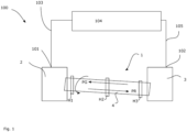
- Fig. 1 shows, based on an exemplary embodiment, a plant arrangement 100 for producing a sponge product with a high degree of metallization.
- a rotary kiln 1 with an inlet section 2 and an outlet section 3.
- metallurgical residues at least one of which contains iron, are introduced, preferably via a lock.
- Converter dust and blast furnace sludge are particularly preferably introduced.
- the metallurgical residues are conveyed through the rotary kiln as the rotary tube of the rotary kiln 1 rotates along a conveying direction PR.
- the metallurgical residues are exposed to a reducing gas which is passed through the rotary kiln in the countercurrent principle, flowing against the conveying direction PR in the countercurrent direction PG.
- a reducing gas which is passed through the rotary kiln in the countercurrent principle, flowing against the conveying direction PR in the countercurrent direction PG.
- This achieves a reduction of compounds contained in the metallurgical residues.
- the interior of the rotary kiln is heated by means of heating elements H1, H2, H3 arranged externally on the rotary kiln.
- the temperature is selected so that the reduction processes take place sufficiently quickly, and the temperatures are not so high that the reduction melts the metallized iron, but are high enough to avoid condensation of metals or metal compounds of other metals that are initially in gaseous form, such as zinc oxides and/or lead chlorides.
- the reduced product which is a sponge product with a high iron content and a high degree of metallization, chemically and structurally very similar to an iron sponge HBI (Hot Briquetted Iron), is removed from a discharge lock in outlet section 3 and then Further use is made, particularly as an intermediate product for the production of pig iron or crude steel. Due to its chemical and structural similarity to sponge iron (HBI, hot briquetted iron), it is preferred that briquetting be carried out after treatment in the rotary kiln.
- HBI hot Briquetted iron
- a gas recirculation system 105 is coupled downstream of the gas processing system 104 for the purpose of recirculating processed reaction gas into the rotary kiln, whereby the recirculation is optional.
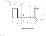
- Fig. 2 shows the basic principle of a rotary kiln 1.
- the functional heart of the rotary kiln 1 is a rotary tube 4, which in technical jargon is often referred to as the The term annealing drum is referenced.
- the rotary tube 4 is mounted for rotation.
- the rotary tube 4 is circularly cylindrical and rotates about a rotation axis R.
- an inlet section 2 is provided, which in the schematic diagram is designed in the form of a housing 2, and which serves in particular to allow the supply of material to be treated in the annealing drum and can be opened and reclosed for this purpose.
- an outlet section 3 On the other side of the rotary tube, an outlet section 3 is provided, which receives the material that has passed through the rotary tube 4 in order to feed it to an openable and resealable removal opening or to another treatment station.
- the rotary tube 4 is arranged between the inlet section 2 and the outlet section 3, wherein the inlet section 2 and the outlet section 3 are stationary relative to the earth's surface, whereas the rotary tube 4 is mounted for rotation relative to the inlet section 2 and the outlet section 4.
- a first sealing arrangement 8 is arranged in a transition region 7 from the inlet section 2 to the rotary tube 3.
- the transition region 7 is to be understood as an area that comprises at least a section of the inlet section 2, a section of the rotary tube 4, and structural measures for coupling the one to the other, whereby an external demarcation is not important, since the transition region is the conceptual requirement to at least take the potential transition point into account.
- a second sealing arrangement 10 is arranged in a transition region 9 from the outlet section 3 to the rotary tube 4.
- the first sealing arrangement 8 has a first mechanical seal 11.
- the second sealing arrangement 10 has a second mechanical seal 11'.
- the material to be treated is transported in the direction of arrow P.
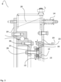
- the Fig. 3 is a partial sectional view of a rotary kiln 1, in which the sealing arrangement 8 is shown to illustrate its function.
- the sealing arrangement 8 is the entirety of the components used in the structural implementation, which either directly provide the seal or which are required for the positioning of the components providing the seal.
- the mechanical seal has a sliding element 12 designed as a sliding flange 12.
- This sliding flange 12 is coupled to the inlet section 2 in a rotationally fixed manner via the fastening flange 17.
- the sliding flange 12 provides a sliding surface 13 in the direction of arrow I, which points toward the interior of the rotary tube.
- the sliding element 12 provides a sliding surface facing the interior of the rotary tube 4.
- the fastening flange 17 is, as already mentioned, non-rotatably coupled to the inlet area 2, it is axially movable, namely in the direction of arrow I.
- a compression spring 14 which, via a bolt 18 in cooperation with the counterflange 19, preloads the sliding element 12 toward the interior of the rotary kiln, i.e., in the direction of arrow I, ensures that the sliding element 12 compensates for a certain degree of wear on the sealing rings (to be described later).
- the preload of the sliding element can be adjusted in the direction of arrow I by screwing the bolt 18 on this side of the expansion spring 14 and on the other side of the counterflange 19.
- An inner sealing element 15, designed as an inner sealing ring 15, and an outer sealing element 16, designed as an outer sealing ring 16, are arranged on a fastening area 20, in this case designed as a fixed flange 20 connected to the rotary tube 4.
- the inner sealing element 15 and the outer sealing element 16 are axially pressed between the fastening area and the sliding surface to ensure a good seal.
- the maintenance of this axial force, which promotes the sealing effect, is ensured by the preload with the compression spring 14 explained above, as well as the possibility of its adjustment.
- the inner sealing element 15, the outer sealing element 16, the fastening area 20 and the sliding surface 13 are dimensioned and positioned such that a continuous sealing space 21 is present between them.
- the sliding element outlet is provided with a Fig. 3 not shown, gas supply device to ensure introduction of a gas into the sealing chamber 22 and continuous maintenance of an overpressure in the sealing chamber 22.
- a fixed bearing half 28 of a ball bearing 28, 29 is positioned with the counter flange 19 in order to effect the rotatable mounting of the rotary tube 4 with the rotating bearing half 29 coupled to the fastening area and thus to the rotary tube via the connecting flange 30.
- a mixture of converter dust and blast furnace sludge was provided as metallurgical residues from the steel industry.
- the mixture was fed into the rotary kiln and conveyed through it in one direction as the rotary kiln rotated. During the conveyance of the metallurgical residues, the mixture was exposed to a reducing gas, which flowed countercurrently through the rotary kiln. Pure H2 was used as the reducing gas, and as the mixture of converter dust and top sludge passed through the rotary kiln, the interior of the rotary kiln was heated to 950 degrees Celsius by indirect electrical heating. The passage time for the mixture through the rotary kiln was 45 minutes.
- the experiment was carried out with two different reference flow rates of the reaction gas, namely 5 Nm 3 /h and 10 Nm 3 /h, where Nm 3 denotes one standard cubic meter and h denotes a period of one hour.
- the exact flow values are not essential to the essence of the invention, as they depend in particular on the specific plant parameters, for example the volume of the rotary kiln and the upstream and downstream units; however, two different flow rates were used to experimentally demonstrate that the addition of the reducing gas, in addition to the selection of suitable reactants, is the decisive factor for the demonstrated production of the sponge product.
- a sponge product can be produced from metallurgical residues using relatively inexpensive aggregates, which can be processed into pig iron or crude steel in a particularly usable manner. In this way, large portions of metallurgical residues are made available for reuse, thus providing a good Sustainability effect is achieved and disposal costs can be reduced.
Landscapes
- Engineering & Computer Science (AREA)
- Mechanical Engineering (AREA)
- General Engineering & Computer Science (AREA)
- Muffle Furnaces And Rotary Kilns (AREA)
Priority Applications (1)
| Application Number | Priority Date | Filing Date | Title |
|---|---|---|---|
| EP23217023.3A EP4571228A1 (fr) | 2023-12-15 | 2023-12-15 | Procédé de récupération d'un produit spongieux ayant un degré de métallisation élevé |
Applications Claiming Priority (1)
| Application Number | Priority Date | Filing Date | Title |
|---|---|---|---|
| EP23217023.3A EP4571228A1 (fr) | 2023-12-15 | 2023-12-15 | Procédé de récupération d'un produit spongieux ayant un degré de métallisation élevé |
Publications (1)
| Publication Number | Publication Date |
|---|---|
| EP4571228A1 true EP4571228A1 (fr) | 2025-06-18 |
Family
ID=89223303
Family Applications (1)
| Application Number | Title | Priority Date | Filing Date |
|---|---|---|---|
| EP23217023.3A Pending EP4571228A1 (fr) | 2023-12-15 | 2023-12-15 | Procédé de récupération d'un produit spongieux ayant un degré de métallisation élevé |
Country Status (1)
| Country | Link |
|---|---|
| EP (1) | EP4571228A1 (fr) |
Citations (7)
| Publication number | Priority date | Publication date | Assignee | Title |
|---|---|---|---|---|
| US3403018A (en) * | 1965-08-31 | 1968-09-24 | Canada Steel Co | Method of treating precipitator dust |
| DE8903410U1 (de) * | 1988-09-09 | 1990-01-04 | Veba Oel Entwicklungs-Gesellschaft mbH, 4650 Gelsenkirchen | Drehrohr |
| EP0538717A1 (fr) * | 1991-10-21 | 1993-04-28 | BELTRAME DANIELI AMBIENTE SpA | Méthode pour le traitement pyrométallurgique d'oxydes de fer et de métaux lourds contenus dans des fumées provenant des fours électriques |
| EP1089044A1 (fr) * | 1999-09-28 | 2001-04-04 | Franz Ragailler | Four à tambour rotatif pour la distillation de déchets organiques, comme par exemple des vieux pneumatiques |
| WO2004108971A2 (fr) | 2003-06-07 | 2004-12-16 | Sms Demag Aktiengesellschaft | Procede et dispositif permettant de produire des produits en acier qui presentent une qualite superficielle optimale |
| CN104357611A (zh) * | 2014-09-29 | 2015-02-18 | 石家庄新华能源环保科技股份有限公司 | 一种利用间壁回转窑还原炼铁的方法和装置 |
| DE102016122087B3 (de) * | 2016-11-17 | 2018-03-29 | Salzgitter Flachstahl Gmbh | Verfahren zur Gewinnung metallischer Bestandteile aus Hüttenreststoffen |
-
2023
- 2023-12-15 EP EP23217023.3A patent/EP4571228A1/fr active Pending
Patent Citations (7)
| Publication number | Priority date | Publication date | Assignee | Title |
|---|---|---|---|---|
| US3403018A (en) * | 1965-08-31 | 1968-09-24 | Canada Steel Co | Method of treating precipitator dust |
| DE8903410U1 (de) * | 1988-09-09 | 1990-01-04 | Veba Oel Entwicklungs-Gesellschaft mbH, 4650 Gelsenkirchen | Drehrohr |
| EP0538717A1 (fr) * | 1991-10-21 | 1993-04-28 | BELTRAME DANIELI AMBIENTE SpA | Méthode pour le traitement pyrométallurgique d'oxydes de fer et de métaux lourds contenus dans des fumées provenant des fours électriques |
| EP1089044A1 (fr) * | 1999-09-28 | 2001-04-04 | Franz Ragailler | Four à tambour rotatif pour la distillation de déchets organiques, comme par exemple des vieux pneumatiques |
| WO2004108971A2 (fr) | 2003-06-07 | 2004-12-16 | Sms Demag Aktiengesellschaft | Procede et dispositif permettant de produire des produits en acier qui presentent une qualite superficielle optimale |
| CN104357611A (zh) * | 2014-09-29 | 2015-02-18 | 石家庄新华能源环保科技股份有限公司 | 一种利用间壁回转窑还原炼铁的方法和装置 |
| DE102016122087B3 (de) * | 2016-11-17 | 2018-03-29 | Salzgitter Flachstahl Gmbh | Verfahren zur Gewinnung metallischer Bestandteile aus Hüttenreststoffen |
Similar Documents
| Publication | Publication Date | Title |
|---|---|---|
| EP2297365B1 (fr) | Procédé et installation de production de fonte avec optimisation énergétique et des émissions de co<sb>2</sb> | |
| DE3042222C2 (de) | Verfahren zur Reduktion von feinkörnigen, unter anderem Eisenoxide enthaltenden Metalloxiden unter Gewinnung von bei der Temperatur der Eisenschmelze flüchtigen Metallen | |
| DE102007032419B4 (de) | Verfahren und Anlage zur Reduktion von eisenoxidhaltigen Feststoffen | |
| DE2420579A1 (de) | Verfahren zur durchfuehrung von endothermen chemischen und/oder physikalischen prozessen | |
| DE69130463T2 (de) | Verfahren und Vorrichtung zur Direktreduktion von Eisenerzen | |
| DE2461153A1 (de) | Verfahren zur reduktion von eisenoxyd zu metallischem eisen mit fluessigen oder festen brennstoffen | |
| WO2023030944A1 (fr) | Procédé de production d'une fonte de fer | |
| EP4361545A1 (fr) | Installation combinée et procédé de fabrication de fonte brute | |
| EP1285096B1 (fr) | Procede et dispositif de production de fonte brute ou de produits semi-finis en acier fluides a partir de matieres de chargement contenant du fer | |
| DE102010022773A1 (de) | Verfahren und Anlage zur Erzeugung von Roheisen | |
| EP1187891B1 (fr) | Procede et dispositif d'elimination de dechets | |
| DE3008445C2 (de) | Verfahren und Vorrichtung zum Reduzieren eines teilchenförmigen Erzes zu Metallpartikeln | |
| DE102021122350A1 (de) | Verfahren zur Herstellung einer Eisenschmelze | |
| DE3423247C2 (de) | Verfahren und Einrichtung zum Herstellen von Stahl aus Schrott | |
| DE4128379C2 (de) | Verfahren und Vorrichtung zur direkten Reduktion von Eisen | |
| DE2715736A1 (de) | Verfahren zur reduktion von vanadiumoxiden | |
| DE102008021562B4 (de) | Verfahren zur Herstellung von Wasserstoffgas mit Hilfe von Hüttenreststoffen und Verwendung von Hüttenreststoffen | |
| EP2185881B1 (fr) | Procédé de traitement de poussières ou de scories contenant des oxydes métalliques, et dispositif pour mettre en oeuvre le procédé | |
| WO2017211939A1 (fr) | Procédé de réduction directe avec utilisation de gaz évacués | |
| EP0117318B1 (fr) | Procédé pour la fusion en continu d'éponge de fer | |
| DE19838368C1 (de) | Verfahren und Vorrichtung zum Betreiben eines Reaktors zur Reduktion von Eisenerzen | |
| DE68913001T2 (de) | Verfahren zur herstellung eines reduziertes chromerz enthaltenden pulvers. | |
| DE69617198T2 (de) | Verfahren zum schmelzen von verzinntem stahlschrott | |
| EP3469106A1 (fr) | Procédé et dispositif de réduction directe avec dépoussiérage à sec des gaz évacués | |
| DE1266330B (de) | Verfahren zur kontinuierlichen Herstellung von kohlenstoffhaltigem Eisen |
Legal Events
| Date | Code | Title | Description |
|---|---|---|---|
| PUAI | Public reference made under article 153(3) epc to a published international application that has entered the european phase |
Free format text: ORIGINAL CODE: 0009012 |
|
| STAA | Information on the status of an ep patent application or granted ep patent |
Free format text: STATUS: THE APPLICATION HAS BEEN PUBLISHED |
|
| AK | Designated contracting states |
Kind code of ref document: A1 Designated state(s): AL AT BE BG CH CY CZ DE DK EE ES FI FR GB GR HR HU IE IS IT LI LT LU LV MC ME MK MT NL NO PL PT RO RS SE SI SK SM TR |
|
| STAA | Information on the status of an ep patent application or granted ep patent |
Free format text: STATUS: REQUEST FOR EXAMINATION WAS MADE |
|
| 17P | Request for examination filed |
Effective date: 20251218 |