EP4571822A1 - Hochdruck-substratbearbeitungsvorrichtung - Google Patents
Hochdruck-substratbearbeitungsvorrichtung Download PDFInfo
- Publication number
- EP4571822A1 EP4571822A1 EP24218595.7A EP24218595A EP4571822A1 EP 4571822 A1 EP4571822 A1 EP 4571822A1 EP 24218595 A EP24218595 A EP 24218595A EP 4571822 A1 EP4571822 A1 EP 4571822A1
- Authority
- EP
- European Patent Office
- Prior art keywords
- housing
- magnetic force
- door
- external
- support protrusion
- Prior art date
- Legal status (The legal status is an assumption and is not a legal conclusion. Google has not performed a legal analysis and makes no representation as to the accuracy of the status listed.)
- Pending
Links
Images


Classifications
-
- B—PERFORMING OPERATIONS; TRANSPORTING
- B03—SEPARATION OF SOLID MATERIALS USING LIQUIDS OR USING PNEUMATIC TABLES OR JIGS; MAGNETIC OR ELECTROSTATIC SEPARATION OF SOLID MATERIALS FROM SOLID MATERIALS OR FLUIDS; SEPARATION BY HIGH-VOLTAGE ELECTRIC FIELDS
- B03C—MAGNETIC OR ELECTROSTATIC SEPARATION OF SOLID MATERIALS FROM SOLID MATERIALS OR FLUIDS; SEPARATION BY HIGH-VOLTAGE ELECTRIC FIELDS
- B03C1/00—Magnetic separation
- B03C1/02—Magnetic separation acting directly on the substance being separated
- B03C1/025—High gradient magnetic separators
- B03C1/031—Component parts; Auxiliary operations
- B03C1/033—Component parts; Auxiliary operations characterised by the magnetic circuit
- B03C1/0332—Component parts; Auxiliary operations characterised by the magnetic circuit using permanent magnets
-
- H—ELECTRICITY
- H10—SEMICONDUCTOR DEVICES; ELECTRIC SOLID-STATE DEVICES NOT OTHERWISE PROVIDED FOR
- H10P—GENERIC PROCESSES OR APPARATUS FOR THE MANUFACTURE OR TREATMENT OF DEVICES COVERED BY CLASS H10
- H10P72/00—Handling or holding of wafers, substrates or devices during manufacture or treatment thereof
- H10P72/04—Apparatus for manufacture or treatment
- H10P72/0441—Apparatus for sealing, encapsulating, glassing, decapsulating or the like
-
- B—PERFORMING OPERATIONS; TRANSPORTING
- B03—SEPARATION OF SOLID MATERIALS USING LIQUIDS OR USING PNEUMATIC TABLES OR JIGS; MAGNETIC OR ELECTROSTATIC SEPARATION OF SOLID MATERIALS FROM SOLID MATERIALS OR FLUIDS; SEPARATION BY HIGH-VOLTAGE ELECTRIC FIELDS
- B03C—MAGNETIC OR ELECTROSTATIC SEPARATION OF SOLID MATERIALS FROM SOLID MATERIALS OR FLUIDS; SEPARATION BY HIGH-VOLTAGE ELECTRIC FIELDS
- B03C1/00—Magnetic separation
- B03C1/02—Magnetic separation acting directly on the substance being separated
- B03C1/30—Combinations with other devices, not otherwise provided for
-
- B—PERFORMING OPERATIONS; TRANSPORTING
- B03—SEPARATION OF SOLID MATERIALS USING LIQUIDS OR USING PNEUMATIC TABLES OR JIGS; MAGNETIC OR ELECTROSTATIC SEPARATION OF SOLID MATERIALS FROM SOLID MATERIALS OR FLUIDS; SEPARATION BY HIGH-VOLTAGE ELECTRIC FIELDS
- B03C—MAGNETIC OR ELECTROSTATIC SEPARATION OF SOLID MATERIALS FROM SOLID MATERIALS OR FLUIDS; SEPARATION BY HIGH-VOLTAGE ELECTRIC FIELDS
- B03C3/00—Separating dispersed particles from gases or vapour, e.g. air, by electrostatic effect
- B03C3/017—Combinations of electrostatic separation with other processes, not otherwise provided for
-
- C—CHEMISTRY; METALLURGY
- C23—COATING METALLIC MATERIAL; COATING MATERIAL WITH METALLIC MATERIAL; CHEMICAL SURFACE TREATMENT; DIFFUSION TREATMENT OF METALLIC MATERIAL; COATING BY VACUUM EVAPORATION, BY SPUTTERING, BY ION IMPLANTATION OR BY CHEMICAL VAPOUR DEPOSITION, IN GENERAL; INHIBITING CORROSION OF METALLIC MATERIAL OR INCRUSTATION IN GENERAL
- C23C—COATING METALLIC MATERIAL; COATING MATERIAL WITH METALLIC MATERIAL; SURFACE TREATMENT OF METALLIC MATERIAL BY DIFFUSION INTO THE SURFACE, BY CHEMICAL CONVERSION OR SUBSTITUTION; COATING BY VACUUM EVAPORATION, BY SPUTTERING, BY ION IMPLANTATION OR BY CHEMICAL VAPOUR DEPOSITION, IN GENERAL
- C23C16/00—Chemical coating by decomposition of gaseous compounds, without leaving reaction products of surface material in the coating, i.e. chemical vapour deposition [CVD] processes
- C23C16/44—Chemical coating by decomposition of gaseous compounds, without leaving reaction products of surface material in the coating, i.e. chemical vapour deposition [CVD] processes characterised by the method of coating
- C23C16/4401—Means for minimising impurities, e.g. dust, moisture or residual gas, in the reaction chamber
-
- C—CHEMISTRY; METALLURGY
- C23—COATING METALLIC MATERIAL; COATING MATERIAL WITH METALLIC MATERIAL; CHEMICAL SURFACE TREATMENT; DIFFUSION TREATMENT OF METALLIC MATERIAL; COATING BY VACUUM EVAPORATION, BY SPUTTERING, BY ION IMPLANTATION OR BY CHEMICAL VAPOUR DEPOSITION, IN GENERAL; INHIBITING CORROSION OF METALLIC MATERIAL OR INCRUSTATION IN GENERAL
- C23C—COATING METALLIC MATERIAL; COATING MATERIAL WITH METALLIC MATERIAL; SURFACE TREATMENT OF METALLIC MATERIAL BY DIFFUSION INTO THE SURFACE, BY CHEMICAL CONVERSION OR SUBSTITUTION; COATING BY VACUUM EVAPORATION, BY SPUTTERING, BY ION IMPLANTATION OR BY CHEMICAL VAPOUR DEPOSITION, IN GENERAL
- C23C16/00—Chemical coating by decomposition of gaseous compounds, without leaving reaction products of surface material in the coating, i.e. chemical vapour deposition [CVD] processes
- C23C16/44—Chemical coating by decomposition of gaseous compounds, without leaving reaction products of surface material in the coating, i.e. chemical vapour deposition [CVD] processes characterised by the method of coating
- C23C16/4412—Details relating to the exhausts, e.g. pumps, filters, scrubbers, particle traps
-
- H—ELECTRICITY
- H10—SEMICONDUCTOR DEVICES; ELECTRIC SOLID-STATE DEVICES NOT OTHERWISE PROVIDED FOR
- H10P—GENERIC PROCESSES OR APPARATUS FOR THE MANUFACTURE OR TREATMENT OF DEVICES COVERED BY CLASS H10
- H10P72/00—Handling or holding of wafers, substrates or devices during manufacture or treatment thereof
- H10P72/04—Apparatus for manufacture or treatment
- H10P72/0402—Apparatus for fluid treatment
-
- H—ELECTRICITY
- H10—SEMICONDUCTOR DEVICES; ELECTRIC SOLID-STATE DEVICES NOT OTHERWISE PROVIDED FOR
- H10P—GENERIC PROCESSES OR APPARATUS FOR THE MANUFACTURE OR TREATMENT OF DEVICES COVERED BY CLASS H10
- H10P72/00—Handling or holding of wafers, substrates or devices during manufacture or treatment thereof
- H10P72/06—Apparatus for monitoring, sorting, marking, testing or measuring
- H10P72/0604—Process monitoring, e.g. flow or thickness monitoring
-
- B—PERFORMING OPERATIONS; TRANSPORTING
- B03—SEPARATION OF SOLID MATERIALS USING LIQUIDS OR USING PNEUMATIC TABLES OR JIGS; MAGNETIC OR ELECTROSTATIC SEPARATION OF SOLID MATERIALS FROM SOLID MATERIALS OR FLUIDS; SEPARATION BY HIGH-VOLTAGE ELECTRIC FIELDS
- B03C—MAGNETIC OR ELECTROSTATIC SEPARATION OF SOLID MATERIALS FROM SOLID MATERIALS OR FLUIDS; SEPARATION BY HIGH-VOLTAGE ELECTRIC FIELDS
- B03C2201/00—Details of magnetic or electrostatic separation
- B03C2201/20—Magnetic separation of bulk or dry particles in mixtures
Definitions
- the present disclosure relates to an apparatus used for processing a substrate at a high pressure.
- various processing may be performed on a semiconductor wafer during a manufacturing process of a semiconductor device.
- An example of the processing may include oxidation, nitriding, deposition, ion implantation, or the like.
- the example may also include a hydrogen or deuterium heat treatment process to improve an interface property of the semiconductor device.
- a gas used for the processing may be supplied to a chamber at a high pressure and act on the semiconductor wafer. It is necessary for the housing and door of the chamber to be firmly fastened with each other to maintain the high pressure in the chamber.
- friction may occur due to their relative movements.
- the friction may form a foreign material, and the foreign material may contaminate the wafer.
- An object of the present disclosure is to provide a high pressure substrate processing apparatus with a minimum possibility that a foreign material contaminates a substrate during a fastening process of a chamber.
- a high pressure substrate processing apparatus includes: an inner chamber accommodating a substrate to be processed and a reaction gas supplied at a first pressure higher than an atmospheric pressure; an outer chamber including an external housing accommodating at least a part of the inner chamber, and an external door movable between a closed state where the external housing is closed and an opened state where the external housing is opened, and accommodating a protective gas supplied at a second pressure set with respect to the first pressure; a fastening module configured to fasten the external housing with the external door in the closed state; and a capture module disposed to be adjacent to a contact position between the external housing and the external door for their fastening, and configured to capture a foreign material.
- the fastening module may include a support protrusion connected to the external housing, and a locking protrusion connected to the external door and supported by the support protrusion by transition from a first relationship where the locking protrusion is offset from the support protrusion to a second relationship where the locking protrusion corresponds to the support protrusion,
- the foreign material may include a metal particle formed by contact between the support protrusion and the locking protrusion during the transition from the first relationship to the second relationship
- the capture module may include a magnetic force unit configured to generate a magnetic force to adsorb the metal particle.
- the magnetic force unit may be installed in one of the external housing and the external door.
- the fastening module may further include a rotating member from which the support protrusion protrudes, and the magnetic force unit may be installed in the external housing through the rotating member.
- the rotating member may include a rotating ring rotatably mounted on the external housing, and the magnetic force unit may be attached to at least one of the support protrusion and the rotating ring.
- the magnetic force unit may include a magnet, and a coating layer covering the magnet to prevent oxidation of the magnet.
- the coating layer may include at least one of nickel, magnesium, titanium, tungsten, and chromium as its coating material.
- the magnetic force unit may include a plurality of magnets forming a circular arrangement around a central axis of the external door.
- the plurality of magnets may be classified into a plurality of groups based on a distance by which the magnet is spaced apart from the central axis.
- a high pressure substrate processing apparatus includes: a chamber including a housing, and a door opening and closing the housing; a fastening module configured to fasten the housing with the door to maintain a process gas injected into the chamber at a pressure higher than an atmospheric pressure; and a capture module disposed to be adjacent to a contact position between the housing and the door for their fastening, and configured to capture a metal particle, wherein the capture module includes a magnetic force unit including a magnet adsorbing the metal particle.
- the fastening module may include a support protrusion connected to the housing, and a locking protrusion connected to the door, and supported by the support protrusion by transition from a first relationship where the locking protrusion is offset from the support protrusion to a second relationship where the locking protrusion corresponds to the support protrusion, and the metal particle may be formed by contact between the support protrusion and the locking protrusion while the support protrusion performs a relative rotation with respect to the locking protrusion for the transition from the first relationship to the second relationship.
- the plurality of magnets may form a circular arrangement around a central axis of the door.
- the magnetic force unit may include a coating layer coated on the magnet with at least one material selected from nickel, magnesium, titanium, tungsten, and chromium.
- the process gas may include a reaction gas which includes an active gas and a protective gas which is an inert gas
- the housing may include an inner housing formed to accommodate a substrate to be processed and the reaction gas, and an external housing accommodating at least a part of the inner housing and coupled to the inner housing to form a closed space for accommodating the protective gas together with the inner housing, and the door may be formed to close the inner housing.
- the fastening module may include a support protrusion connected to the external housing, and a locking protrusion connected to the door and transitioned from a first relationship where the locking protrusion is offset from the support protrusion to a second relationship where the locking protrusion is supported by the support protrusion as the door is rotated, and the magnetic force unit may be configured to collect a foreign material formed by contact between the support protrusion and the locking protrusion during the transition from the first relationship to the second relationship.
- FIG. 1 is a conceptual view of a high pressure substrate processing apparatus 100 according to an embodiment of the present disclosure.
- the high pressure substrate processing apparatus 100 may include an inner chamber 110, an outer chamber 120, a gas supply module 130, and a gas exhaust module 140.
- the inner chamber 110 may have a processing area for accommodating a substrate to be processed.
- the inner chamber 110 may be made of a non-metallic material, for example, quartz, to reduce a substrate contamination risk in a high pressure and high temperature working environment.
- a heater (not shown) disposed outside the inner chamber 110 is operated, a temperature of the inner chamber 110 may reach hundreds to thousands of degrees Celsius.
- the substrate may be, for example, a semiconductor wafer W (see FIG. 2 ) mounted on a holder 113 (see FIG. 2 ).
- the substrate is not limited to the wafer, and may be any other base structure for making a circuit.
- the substrate may also include glass for producing a display.
- the holder 113 may be a boat which may stack the substrates to be processed in a plurality of layers.
- the outer chamber 120 is disposed to accommodate at least a part of the inner chamber 110. Unlike the inner chamber 110, the outer chamber 120 is free from the substrate contamination risk, and may thus be made of a metallic material.
- the outer chamber 120 may have a hollow protective area for accommodating the inner chamber 110.
- the gas supply module 130 may be a component supplying a gas to the inner chamber 110 and the outer chamber 120.
- the gas supply module 130 may have a gas supplier 131 communicated with utility (or gas supply facility) of a semiconductor factory.
- the gas supplier 131 may selectively provide the inner chamber 110 with a reaction gas, for example, a hydrogen gas (H 2 ), a deuterium gas (D 2 ), a fluorine gas (F 2 ), an ammonia gas (NH 3 ), a chlorine gas (Cl 2 ), or a nitrogen gas (N 2 ).
- the gas supplier 131 may provide the outer chamber 120 with, for example, the nitrogen gas or an argon gas (Ar), which is an inert gas, as a protective gas.
- the reaction gas and the protective gas may each be injected into the internal chamber 110 or the external chamber 120 through a reaction gas line 133 or a protective gas line 135.
- the protective gas injected into the outer chamber 120 may be injected into a space (protective space) between the outer chamber 120 and the inner chamber 110.
- the reaction gas and the protective gas may simply be referred to as a process gas.
- the process gas may be supplied to form a pressure higher than an atmospheric pressure (high pressure), for example, ranging from several atmospheres to tens of atmospheres, or more.
- high pressure atmospheric pressure
- a pressure of the reaction gas in the internal chamber 110 is a first pressure
- a pressure of the protective gas in the external chamber 120 is a second pressure
- these pressures may maintain a predetermined relationship (or range).
- the second pressure may be set to be substantially equal to or slightly greater than the first pressure.
- Such a pressure relationship may prevent leakage of the reaction gas from the inner chamber 110 and breakage of the inner chamber 110.
- the second pressure may be set to be slightly lower than the first pressure, and a similar effect as before may be achieved even in that case.
- the gas exhaust module 140 may be a component exhausting the process gas.
- a gas exhaust pipe 141 may be connected to an upper portion of the inner chamber 110.
- a gas exhaust pipe 145 connected to the outer chamber 120 may be provided to exhaust the protective gas from the outer chamber 120.
- These gas exhaust pipes 141 and 145 may be communicated with each other, and the reaction gas may thus be diluted with the protective gas in its exhaust process to have a lower concentration.
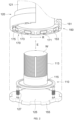
- FIG. 2 is a perspective view showing an opened state where an external housing 121 is opened by an external door 125 in the high pressure substrate processing apparatus 100 of FIG. 1 ;
- FIG. 3 is a cross-sectional view showing a relationship between a support protrusion 153 and a locking protrusion 155 when implementing a closed state where the external housing 121 is closed by the external door 125 in FIG. 2 ;
- FIG. 4 is a partial perspective view showing a fastened state between the external housing 121 and external door 125 in the high pressure substrate processing apparatus 100 of FIG. 2 .
- the inner chamber 110 may include an inner housing (not shown) and an inner door 115.
- the inner housing may have a processing area for accommodating a substrate W, and its lower portion may be open.
- the inner housing may be mounted on the external housing 121 described below.
- the inner door 115 may close the open lower portion of the inner housing.
- the inner door 115 may have a shape of a trough generally open downward.
- the opening/closing direction E may be the direction in which the inner door 115 gets closer to or further away from the inner housing.
- the substrate W may be loaded into the processing area or unloaded from the processing area.
- the inner door 115 may come into contact with the inner housing. In this case, the processing area may be closed (or in the closed state).
- the outer chamber 120 may also include the external housing 121 and the external door 125.
- the external housing 121 may entirely accommodate the inner chamber 110. Accordingly, the external housing 121 may surround not only the inner housing but also the inner door 115.
- the external door 125 may also open and close the external housing 121 by its movement.
- the external door 125 may be connected to the inner door 115 by a support member 127 to thus support the inner door 115. In that case, the inner door 115 may open and close the inner housing while being moved in conjunction with the ascending and descending of the external door 125.
- the expressions "opened state” and "closed state” may also be applied to a relationship between the external housing 121 and the external door 125 as they are. Unlike the above, the inner door 115 may be opened and closed independently from the external door 125.
- the high pressure substrate processing apparatus 100 may further include a fastening module 150 fastening the external housing 121 with the external door 125 in the closed state.
- the fastening module 150 may allow the protective gas to maintain the second pressure in the outer chamber 120.
- the fastening module 150 may also fasten the inner door 115 to the inner housing. As a result, the fastening module 150 may allow the reaction gas to maintain the first pressure in the inner chamber 110.
- the fastening module 150 may include a rotating member 151, the support protrusion 153, and the locking protrusion 155.
- the rotating member 151 may be a component rotatably connected to the external housing 121 or the external door 125.
- the rotating member 151 may be a rotating ring mounted on the external housing 121.
- the rotating ring 151 may be disposed to surround an outer peripheral surface of the external housing 121, and may be rotated around a central axis of the external housing 121.
- a force for rotating the rotating ring 151 may be provided from a driving wheel (not shown) engaged with the rotating ring 151.
- the rotating ring 151 may form a second plane parallel to a first plane formed by the support protrusion 153 or the locking protrusion 155, which are described below.
- Each of the first and second planes may be a plane generally perpendicular to the opening/closing direction E.
- the support protrusion 153 may be a protrusion connected to the external housing 121.
- the support protrusion 153 may be connected to the external housing 121 through the rotating ring 151.
- the support protrusion 153 may protrude from an inner peripheral surface of the rotating ring 151, for example.
- the plurality of support protrusions 153 may be arranged in a circumferential direction of the rotating ring 151.
- the locking protrusion 155 may be a protrusion connected to the external door 125.
- the locking protrusion 155 may protrude from an outer peripheral surface of the external door 125.
- the locking protrusion 155 may have a size in which the locking protrusion 155 passes between the pair of adjacent support protrusions 153.
- the locking protrusion 155 may be disposed at a higher level than the support protrusion 153 in the closed state (see FIG. 3 ).
- the locking protrusion 155 may be disposed on the support protrusion 153, and supported by the support protrusion 153 (or in the fastened state, see FIG. 4 ).
- a level of the external door 125 in the fastened state may be substantially the same as that in the closed state.
- the fastened state may be understood as one of the closed states.
- the closed state may be achieved when the external door 125 ascends in the opening/closing direction E while the locking protrusion 155 is disposed to be offset from the support protrusion 153 (or in a first relationship, see FIG. 3 ).
- the support protrusion 153 may be rotated with respect to the locking protrusion 155.
- An upper surface of the support protrusion 153 may be rotated while being in contact with a lower surface of the locking protrusion 155.
- the supporting protrusion 153 may be disposed to correspond to the locking protrusion 155 (or in a second relationship, see FIG. 4 ).
- a foreign material may be formed by a fastening operation (in detail, the rotation of the rotating ring 151 for transition from the first relationship to the second relationship (or vice versa)) of the fastening module 150 or the like.
- the high pressure substrate processing apparatus 100 may further include a capture module 170 capturing the foreign material.
- the foreign material may be a particle formed by the contact between the support protrusion 153 and the locking protrusion 155, or a particle floating around the support protrusion 153 and the locking protrusion 155 due to a cause other than the contact.
- the former particle may be formed by friction between the upper surface of the support protrusion 153 and the lower surface of the locking protrusion 155.
- the capture module 170 may be an electric force unit capturing the foreign material by using a force acting between electric charges.
- the electric force unit may be one (an electrostatic filter) in which positive and negative charges are separated from each other to form static electricity as an ultra-high voltage current is applied to a nonwoven fabric.
- the capture module 170 may include a tape with an adhesive component. The electric force unit and the adhesive tape may be installed at approximately the same location as an installation location of the magnetic force unit described below.
- the particle may mainly have a metal component. Accordingly, the capture module 170 may include the magnetic force unit generating a magnetic force to adsorb the metal particle.
- the magnetic force unit may be installed on the rotating ring 151. As the rotating ring 151 is mounted on the external housing 121, the magnetic force unit may be installed in the external housing 121 as a result. This arrangement may be distinguishable from the configuration that the magnetic force unit is installed on the external door 125.
- the magnetic force units may be classified into a first magnetic force unit 171, a second magnetic force unit 173, and a third magnetic force unit 175.
- the magnetic force units 171, 173, and 175 may each be provided as the plurality of magnetic force units.
- the first magnetic force units 171 to the third magnetic force units 175 may each be grouped based on their arrangement location, shape, etc.
- the second magnetic force unit 173 may be attached to a space between the pair of adjacent support protrusions 153 on the inner peripheral surface of the rotating ring 151.
- the third magnetic force unit 175 may be attached to a bottom surface of the rotating ring 151.
- the first magnetic force unit 171 and the second magnetic force unit 173 may be disposed in a space defined by an inner surface of the external housing 121.
- the third magnetic force unit 175 may be disposed in a space defined by an outer surface of the external housing 121.
- the first magnetic force unit 171 to the third magnetic force unit 175 may all be adopted, or only one or two of the magnetic force units may be adopted.
- one magnetic force unit may be provided rather than the plurality of magnetic force units of one type.
- the first magnetic force unit 171 to the third magnetic force unit 175 may be disposed to be adjacent to a contact position between the support protrusion 153 and the locking protrusion 155.
- the magnetic force units 171, 173, and 175 may be generally disposed between an upper boundary UL corresponding to the upper surface of the locking protrusion 155 and a lower boundary LL corresponding to the lower surface of the support protrusion 153 along the opening/closing direction E (see FIG. 3 ).
- the upper boundary UL may be set as high as a thickness of the locking protrusion 155 or several times higher than the corresponding thickenss
- the lower boundary LL may be set as low as a thickness of the support protrusion 153 or several times lower than the corresponding thickenss.
- the magnetic force units 171, 173, and 175 may be disposed at a lower height than the contact position. This arrangement may be advantageous for the magnetic force units 171, 173, and 175 to capture the metal particles descending from the contact position.
- the magnetic force unit may be directly installed on the external door 125, or may be installed on the external door 125 through the locking protrusion 155.
- the magnetic force unit may be disposed on a side surface of the locking protrusion 155 or between the pair of adjacent locking protrusions 155.
- the magnetic force units may also be attached to the plurality of outer surfaces of the external door 125.
- the magnetic force units may be attached to the side and bottom surfaces of the external door 125.
- the magnetic force unit may be disposed outside a closed space defined by the external housing 121 and the external door 125.
- the closed space may be a space where the process gas, specifically, the protective gas, is injected.
- FIGS. 5A to 5C are perspective views individually showing the magnetic force units 171, 173, and 175 of FIG. 4 .
- each of the first magnetic force unit 171 to the third magnetic force unit 175 may have a shape and a size which correspond to an area to which the magnetic force unit is attached.
- each of the first magnetic force unit 171 and the second magnetic force unit 173 may be generally rectangular, and the third magnetic force unit 175 may be generally circular.
- Each of the magnetic force units 171, 173, and 175 is not limited to an exemplified shape (or size), and may have another shape.
- the third magnetic force unit 175 may have a ring shape or a curved shape corresponding to the bottom surface of the rotating ring 151. It may be advantageous for each of the magnetic force units 171, 173, and 175 to capture the metal particle when having a main surface area which is as large as an installation target allows.
- the first magnetic force unit 171 may have a magnet generating the magnetic force.
- the magnet may be a neodymium magnet.
- N north
- S south
- each of the front portion and the back portion may be a region corresponding to a main surface of the magnet.
- a display part (not shown) indicating a polarity of the magnet may be formed on the front portion.
- the display part may be a marker for indicating the N pole 171a, and may be, for example, a dot or a character (e.g., 'N'), which is formed on the front portion.
- the dot or the character may be printed, embossed, or engraved on the front portion.
- An outer surface of the magnet may be covered with a coating layer 171c.
- the coating layer 171c may be provided to prevent oxidation of the magnet.
- a coating material for forming the coating layer 171c may be, for example, selected from nickel, magnesium, titanium, tungsten, and chromium.
- the coating layer 171c may be an alloy of different materials among the coating materials.
- the coating layer 171c may also be a stack of single materials or a stack of alloys of the single materials, among the coating materials.
- FIG. 6 is a perspective view for explaining an arrangement of the capture module 170.
- the plurality of magnetic force units 171, 173, and 175 may form a circular arrangement around a central axis C of the external door 125.
- the magnetic force units 171, 173, and 175 may be spaced apart from the central axis C by different distances.
- Each of the plurality of first magnetic force units 171 may be spaced apart from the central axis C by a first distance D1
- each of the plurality of second magnetic force units 173 may be spaced apart from the central axis C by a second distance D2.
- Each of the plurality of third magnetic force units 175 may be spaced apart from the central axis C by a third distance D3.
- the first distance D1 may be the shortest
- the second distance D2 and the third distance D3 may be similar to each other.
- the magnetic force units 171, 173, and 175 may be arranged to have the same magnetic pole disposed on each of their surfaces facing the central axis C.
- the N poles may all be disposed on the main surfaces of the first magnetic force unit 171 and the second magnetic force unit 173 that face the central axis C.
- the N pole of the third magnetic force unit 175 may be disposed on its surface exposed to the outside.
- the first magnetic force unit 171 may most effectively adsorb the metal particle.
- the metal particle formed in a contact process between the locking protrusion 155 and the support protrusion 153 may fall toward the nearest first magnetic force unit 171 (see F1), and the first magnetic force unit 171 may thus most effectively capture the metal particle.
- Some of the metal particles may fall on both sides of the support protrusion 153 (see F2), and the second magnetic force unit 173 may thus capture these metal particles.
- a laminar flow may be formed from the inner space to the outside. This laminar flow may carry the metal particles not only to the inner peripheral surface of the rotating ring 151 but also to its bottom surface (see F3).
- the third magnetic force unit 175 may thus also capture some of the metal particles.
- the rotating ring as the rotating member may be rotatably connected to the external door.
- the locking protrusion may be formed on the rotating ring.
- the capture module may be installed in the external housing, and may capture the particle formed by relative rotations of the locking protrusion and the support protrusion. The capture module may still be disposed outside the closed space defined by the external door and the external housing.
- the external door may be rotated in a state where the locking protrusion is connected to the external door.
- a tool such as a bearing, which may block a rotational force of the external door from being transmitted to the inner door may be installed between the inner door and the external door. In this case, the substrate may not be rotated despite the rotation of the external door.
- the collection module may be installed in the external housing, the external door, or the like.
- the locking protrusion 155 may be moved with respect to the support protrusion 153 in a manner other than the rotational motion, for example, by a translational motion.
- the metal particle formed during the transition from the first relationship to the second relationship may be captured by the capture module 170.
- the foreign material derived from the fastening operation of fastening the housing and door of the chamber for the high pressure processing of the substrate may be captured by the capture module.
- the foreign material resulting from the fastening operation may thus be removed before the foreign material affects the substrate. It is thus possible to minimize the possibility of the substrate contamination by the foreign material.
- the specification exemplifies the processing apparatus having double chambers 110 and 120 as the high pressure substrate processing apparatus 100.
- the single chamber may include one housing and one door.
- the substrate may be disposed in the chamber, and the process gas for processing the substrate, the reaction gas in detail, may be supplied to the chamber.
- the fastening module 150 and the capture module 170 may also be applied to this single chamber as they are.
- the configurations of the fastening module 150 and the collection module 170 may also be applied to a semi-dual chamber, which is an intermediate form between dual chamber and single chamber.
- the semi-dual chamber may have two housings (inner housing and external housing) and one door.
- the two housings may be coupled to each other by their own shapes or by having a separate member intervened therebetween to thus form a closed space (corresponding to the protective space).
- the substrate may be disposed in the processing chamber of the inner housing and the reaction gas may be injected into the processing chamber, and the protective gas may be injected into the closed space.
- the door may not be completely protected by the protective gas, and may be exposed to the outside.
- the door may correspond to the external door in the previous embodiment.
- the door may open and close the inner housing.
Landscapes
- Chemical & Material Sciences (AREA)
- Engineering & Computer Science (AREA)
- Chemical Kinetics & Catalysis (AREA)
- Metallurgy (AREA)
- Materials Engineering (AREA)
- Mechanical Engineering (AREA)
- General Chemical & Material Sciences (AREA)
- Organic Chemistry (AREA)
- Container, Conveyance, Adherence, Positioning, Of Wafer (AREA)
- Power Engineering (AREA)
- Cleaning Or Drying Semiconductors (AREA)
- Physics & Mathematics (AREA)
- Electromagnetism (AREA)
- Crystallography & Structural Chemistry (AREA)
- Inorganic Chemistry (AREA)
Applications Claiming Priority (1)
| Application Number | Priority Date | Filing Date | Title |
|---|---|---|---|
| US18/536,583 US20250187021A1 (en) | 2023-12-12 | 2023-12-12 | High pressure substrate processing apparatus |
Publications (1)
| Publication Number | Publication Date |
|---|---|
| EP4571822A1 true EP4571822A1 (de) | 2025-06-18 |
Family
ID=93853368
Family Applications (1)
| Application Number | Title | Priority Date | Filing Date |
|---|---|---|---|
| EP24218595.7A Pending EP4571822A1 (de) | 2023-12-12 | 2024-12-10 | Hochdruck-substratbearbeitungsvorrichtung |
Country Status (6)
| Country | Link |
|---|---|
| US (1) | US20250187021A1 (de) |
| EP (1) | EP4571822A1 (de) |
| JP (1) | JP7791299B2 (de) |
| KR (1) | KR102762743B1 (de) |
| CN (1) | CN120149195A (de) |
| IL (1) | IL317557A (de) |
Citations (2)
| Publication number | Priority date | Publication date | Assignee | Title |
|---|---|---|---|---|
| KR20150086831A (ko) * | 2014-01-20 | 2015-07-29 | 주식회사 풍산 | 반도체 기판 처리용 챔버 개폐장치 |
| WO2022128112A1 (en) * | 2020-12-17 | 2022-06-23 | Applied Materials, Inc. | Roller for a carrier transport assembly, substrate processing system, method of maintaining a substrate processing system, and method of manufacturing a device |
Family Cites Families (5)
| Publication number | Priority date | Publication date | Assignee | Title |
|---|---|---|---|---|
| JPH02138518A (ja) * | 1988-11-16 | 1990-05-28 | Hitachi Ltd | 摺動部材および摺動装置 |
| JP2554448Y2 (ja) * | 1991-08-12 | 1997-11-17 | 神鋼電機株式会社 | すべり摩擦部を有する機器の摩耗粉排除装置 |
| JP3305786B2 (ja) * | 1992-12-26 | 2002-07-24 | 住友特殊金属株式会社 | 耐食性のすぐれた永久磁石の製造方法 |
| JP2014107412A (ja) | 2012-11-28 | 2014-06-09 | Tokyo Electron Ltd | 搬送システム及び成膜装置 |
| KR102606703B1 (ko) * | 2022-11-04 | 2023-11-29 | 주식회사 에이치피에스피 | 고압 열처리 장치 |
-
2023
- 2023-12-12 US US18/536,583 patent/US20250187021A1/en active Pending
- 2023-12-14 KR KR1020230182281A patent/KR102762743B1/ko active Active
-
2024
- 2024-12-09 IL IL317557A patent/IL317557A/en unknown
- 2024-12-10 EP EP24218595.7A patent/EP4571822A1/de active Pending
- 2024-12-11 JP JP2024216297A patent/JP7791299B2/ja active Active
- 2024-12-12 CN CN202411826105.2A patent/CN120149195A/zh active Pending
Patent Citations (2)
| Publication number | Priority date | Publication date | Assignee | Title |
|---|---|---|---|---|
| KR20150086831A (ko) * | 2014-01-20 | 2015-07-29 | 주식회사 풍산 | 반도체 기판 처리용 챔버 개폐장치 |
| WO2022128112A1 (en) * | 2020-12-17 | 2022-06-23 | Applied Materials, Inc. | Roller for a carrier transport assembly, substrate processing system, method of maintaining a substrate processing system, and method of manufacturing a device |
Also Published As
| Publication number | Publication date |
|---|---|
| KR102762743B1 (ko) | 2025-02-06 |
| JP2025093899A (ja) | 2025-06-24 |
| TW202524636A (zh) | 2025-06-16 |
| US20250187021A1 (en) | 2025-06-12 |
| JP7791299B2 (ja) | 2025-12-23 |
| CN120149195A (zh) | 2025-06-13 |
| IL317557A (en) | 2025-07-01 |
Similar Documents
| Publication | Publication Date | Title |
|---|---|---|
| EP1630261B1 (de) | Substratträger für eine Dampfabscheidungsvorrichtung | |
| JP5192492B2 (ja) | 真空処理装置、当該真空処理装置を用いた画像表示装置の製造方法及び当該真空処理装置により製造される電子装置 | |
| US7276123B2 (en) | Semiconductor-processing apparatus provided with susceptor and placing block | |
| US5037262A (en) | Holding device for a disk and application therefor | |
| TWI693664B (zh) | 用於腔室接口的氣體裝置、系統及方法 | |
| WO2014150260A1 (en) | Process load lock apparatus, lift assemblies, electronic device processing systems, and methods of processing substrates in load lock locations | |
| US20210375650A1 (en) | High temperature and vacuum isolation processing mini-environments | |
| CN112680710B (zh) | 薄膜沉积腔、多功能遮蔽盘以及多功能遮蔽盘的使用方法 | |
| US20100212592A1 (en) | Vacuum processing apparatus | |
| TW201707128A (zh) | 基板保持裝置、成膜裝置以及基板保持方法 | |
| CN106165056A (zh) | 基板载体 | |
| TW201941337A (zh) | 用於處理縮小尺寸的基板的處理套件 | |
| JP2019099882A (ja) | Pvd処理方法およびpvd処理装置 | |
| EP4571822A1 (de) | Hochdruck-substratbearbeitungsvorrichtung | |
| WO2024025952A1 (en) | Multi-piece slit valve gate | |
| US20060081468A1 (en) | Magnetic latch for a vapour deposition system | |
| TWI920921B (zh) | 高壓基板處理裝置 | |
| US11770049B2 (en) | Generating electric power for a robotic end effector | |
| WO2019063074A1 (en) | MASK ARRANGEMENT FOR MASKING A SUBSTRATE, SUBSTRATE PROCESSING APPARATUS AND METHOD THEREOF | |
| KR102595812B1 (ko) | 홀더, 적어도 2개의 홀더들을 포함하는 캐리어, 장치들 및 방법들 | |
| TWI673797B (zh) | 製程零件、半導體製造設備及半導體製造方法 | |
| TW200920867A (en) | Magnetron sputter cathode mechanism | |
| JP2016003388A (ja) | 板状部材の固定機構、pvd処理装置及び板状部材の固定方法 | |
| CN114664624B (zh) | 聚焦环及包括聚焦环的基板处理装置 | |
| CN116917533B (zh) | 基板支撑件、处理基板的方法、以及处理系统 |
Legal Events
| Date | Code | Title | Description |
|---|---|---|---|
| PUAI | Public reference made under article 153(3) epc to a published international application that has entered the european phase |
Free format text: ORIGINAL CODE: 0009012 |
|
| STAA | Information on the status of an ep patent application or granted ep patent |
Free format text: STATUS: THE APPLICATION HAS BEEN PUBLISHED |
|
| AK | Designated contracting states |
Kind code of ref document: A1 Designated state(s): AL AT BE BG CH CY CZ DE DK EE ES FI FR GB GR HR HU IE IS IT LI LT LU LV MC ME MK MT NL NO PL PT RO RS SE SI SK SM TR |
|
| STAA | Information on the status of an ep patent application or granted ep patent |
Free format text: STATUS: REQUEST FOR EXAMINATION WAS MADE |
|
| 17P | Request for examination filed |
Effective date: 20251218 |