EP4571867A1 - Procédé de fabrication d'électrode sèche et système de fabrication d'électrode sèche - Google Patents
Procédé de fabrication d'électrode sèche et système de fabrication d'électrode sèche Download PDFInfo
- Publication number
- EP4571867A1 EP4571867A1 EP23912891.1A EP23912891A EP4571867A1 EP 4571867 A1 EP4571867 A1 EP 4571867A1 EP 23912891 A EP23912891 A EP 23912891A EP 4571867 A1 EP4571867 A1 EP 4571867A1
- Authority
- EP
- European Patent Office
- Prior art keywords
- electrode
- primer layer
- powder
- dam
- manufacturing
- Prior art date
- Legal status (The legal status is an assumption and is not a legal conclusion. Google has not performed a legal analysis and makes no representation as to the accuracy of the status listed.)
- Pending
Links
Images


Classifications
-
- H—ELECTRICITY
- H01—ELECTRIC ELEMENTS
- H01M—PROCESSES OR MEANS, e.g. BATTERIES, FOR THE DIRECT CONVERSION OF CHEMICAL ENERGY INTO ELECTRICAL ENERGY
- H01M4/00—Electrodes
- H01M4/02—Electrodes composed of, or comprising, active material
- H01M4/04—Processes of manufacture in general
-
- H—ELECTRICITY
- H01—ELECTRIC ELEMENTS
- H01M—PROCESSES OR MEANS, e.g. BATTERIES, FOR THE DIRECT CONVERSION OF CHEMICAL ENERGY INTO ELECTRICAL ENERGY
- H01M4/00—Electrodes
- H01M4/02—Electrodes composed of, or comprising, active material
- H01M4/04—Processes of manufacture in general
- H01M4/0402—Methods of deposition of the material
- H01M4/0404—Methods of deposition of the material by coating on electrode collectors
-
- H—ELECTRICITY
- H01—ELECTRIC ELEMENTS
- H01M—PROCESSES OR MEANS, e.g. BATTERIES, FOR THE DIRECT CONVERSION OF CHEMICAL ENERGY INTO ELECTRICAL ENERGY
- H01M4/00—Electrodes
- H01M4/02—Electrodes composed of, or comprising, active material
- H01M4/04—Processes of manufacture in general
- H01M4/0402—Methods of deposition of the material
- H01M4/0419—Methods of deposition of the material involving spraying
-
- H—ELECTRICITY
- H01—ELECTRIC ELEMENTS
- H01M—PROCESSES OR MEANS, e.g. BATTERIES, FOR THE DIRECT CONVERSION OF CHEMICAL ENERGY INTO ELECTRICAL ENERGY
- H01M4/00—Electrodes
- H01M4/02—Electrodes composed of, or comprising, active material
- H01M4/04—Processes of manufacture in general
- H01M4/043—Processes of manufacture in general involving compressing or compaction
- H01M4/0435—Rolling or calendering
-
- H—ELECTRICITY
- H01—ELECTRIC ELEMENTS
- H01M—PROCESSES OR MEANS, e.g. BATTERIES, FOR THE DIRECT CONVERSION OF CHEMICAL ENERGY INTO ELECTRICAL ENERGY
- H01M4/00—Electrodes
- H01M4/02—Electrodes composed of, or comprising, active material
- H01M4/13—Electrodes for accumulators with non-aqueous electrolyte, e.g. for lithium-accumulators; Processes of manufacture thereof
-
- H—ELECTRICITY
- H01—ELECTRIC ELEMENTS
- H01M—PROCESSES OR MEANS, e.g. BATTERIES, FOR THE DIRECT CONVERSION OF CHEMICAL ENERGY INTO ELECTRICAL ENERGY
- H01M4/00—Electrodes
- H01M4/02—Electrodes composed of, or comprising, active material
- H01M4/13—Electrodes for accumulators with non-aqueous electrolyte, e.g. for lithium-accumulators; Processes of manufacture thereof
- H01M4/139—Processes of manufacture
-
- H—ELECTRICITY
- H01—ELECTRIC ELEMENTS
- H01M—PROCESSES OR MEANS, e.g. BATTERIES, FOR THE DIRECT CONVERSION OF CHEMICAL ENERGY INTO ELECTRICAL ENERGY
- H01M4/00—Electrodes
- H01M4/02—Electrodes composed of, or comprising, active material
- H01M4/62—Selection of inactive substances as ingredients for active masses, e.g. binders, fillers
-
- H—ELECTRICITY
- H01—ELECTRIC ELEMENTS
- H01M—PROCESSES OR MEANS, e.g. BATTERIES, FOR THE DIRECT CONVERSION OF CHEMICAL ENERGY INTO ELECTRICAL ENERGY
- H01M4/00—Electrodes
- H01M4/02—Electrodes composed of, or comprising, active material
- H01M4/64—Carriers or collectors
- H01M4/66—Selection of materials
- H01M4/665—Composites
- H01M4/667—Composites in the form of layers, e.g. coatings
-
- H—ELECTRICITY
- H01—ELECTRIC ELEMENTS
- H01M—PROCESSES OR MEANS, e.g. BATTERIES, FOR THE DIRECT CONVERSION OF CHEMICAL ENERGY INTO ELECTRICAL ENERGY
- H01M50/00—Constructional details or processes of manufacture of the non-active parts of electrochemical cells other than fuel cells, e.g. hybrid cells
- H01M50/40—Separators; Membranes; Diaphragms; Spacing elements inside cells
- H01M50/471—Spacing elements inside cells other than separators, membranes or diaphragms; Manufacturing processes thereof
- H01M50/474—Spacing elements inside cells other than separators, membranes or diaphragms; Manufacturing processes thereof characterised by their position inside the cells
-
- Y—GENERAL TAGGING OF NEW TECHNOLOGICAL DEVELOPMENTS; GENERAL TAGGING OF CROSS-SECTIONAL TECHNOLOGIES SPANNING OVER SEVERAL SECTIONS OF THE IPC; TECHNICAL SUBJECTS COVERED BY FORMER USPC CROSS-REFERENCE ART COLLECTIONS [XRACs] AND DIGESTS
- Y02—TECHNOLOGIES OR APPLICATIONS FOR MITIGATION OR ADAPTATION AGAINST CLIMATE CHANGE
- Y02E—REDUCTION OF GREENHOUSE GAS [GHG] EMISSIONS, RELATED TO ENERGY GENERATION, TRANSMISSION OR DISTRIBUTION
- Y02E60/00—Enabling technologies; Technologies with a potential or indirect contribution to GHG emissions mitigation
- Y02E60/10—Energy storage using batteries
Definitions
- the present disclosure relates to a method for manufacturing a dry electrode by a powder coating process and its manufacturing system.
- lithium secondary batteries are used as not only an energy source of mobile devices but also a power source of electric vehicles and hybrid electric vehicles as an alternative to vehicles using fossil fuels such as gasoline vehicles and diesel vehicles that are regarded as one of the main causes of air pollution, and they have a diverse range of application including use as an auxiliary power source via a grid.
- an electrode manufacturing process includes an electrode material mixing process, an electrode coating process, a drying process, a rolling process, a slitting process and a winding process
- the electrode material mixing process is a process of mixing the components for forming an electrode active material layer, and the electrode material including an electrode active material, a binder, etc. may be mixed with a solvent into a flowable slurry.
- the electrode coating process of coating the electrode materials prepared into the slurry on a current collector and the drying process for removing the solvent from the electrode mixture are performed, followed by rolling, to manufacture an electrode with a predetermined thickness.
- the electrode active material layer may not uniformly dried all over the entire inner/outer area, and a powder floating phenomenon is generated due to a difference in solvent evaporation rate, i.e., some regions get dried earlier and powder at the corresponding regions float, and thus form a gap with some other regions get dried later, resulting in low quality of the electrode.
- a dry electrode is generally manufactured by preparing an electrode powder including an electrode active material and a binder resin, and coating the electrode powder on the surface of a current collector, followed by compression.
- the dry electrode manufactured by the dry manufacturing method has uniform binder resin distribution in the thickness direction of the electrode active material layer and fewer defects such as pinholes or cracks, compared to the slurry coating method.
- the electrode powder may flow down at the edge of the electrode active material layer, or the electrode powder may be pressed out at the edge of the electrode active material layer during compression, resulting in uneven side finishes.
- the present disclosure is directed to providing a method for manufacturing a dry electrode with improved edge quality of an electrode active material layer.
- the present disclosure is further directed to providing a system for manufacturing a dry electrode with improved edge quality of an electrode active material layer.
- a method for manufacturing a dry electrode of the following embodiments there is provided a method for manufacturing a dry electrode of the following embodiments.
- the method for manufacturing the dry electrode according to a first embodiment includes (S10) forming a primer layer having a predetermined width on at least one surface of a current collector; (S20) forming a dam on two widthwise sides of the primer layer to prevent an electrode powder from flowing down; (S30) feeding the electrode powder onto a surface of the primer layer; and (S40) compressing the electrode powder to form an electrode active material layer.
- the dam may extend outward from the current collector surface, have a height that is greater than a height of the primer layer and be disposed in close contact with the sides of the primer layer without a gap.
- the method for manufacturing the dry electrode may further include, after the step (S40) is performed, (S50) removing the electrode active material layer protruding out of the dam.
- the step (S50) may be performed by laser irradiation or knife type etching.
- the dam may include a material that does not change physical and chemical properties of the primer layer and the electrode powder when it contacts the primer layer and the electrode powder.
- the dam may include a polymer material.
- the step (S20) may be performed by printing.
- the electrode powder may include an electrode active material and a binder resin for the electrode.
- the electrode powder may be produced by spray drying.
- the primer layer may include a conductive material for the primer layer and a binder resin for the primer layer.
- the dry electrode according to an eleventh embodiment is a dry electrode obtained by the method for manufacturing the dry electrode according to any one of the first to tenth embodiments, and includes the current collector, and the electrode active portion on at least one surface of the current collector, wherein the electrode active portion includes the primer layer and the electrode active material layer on the primer layer, and wherein the dam covers all or at least part of the side of the electrode active portion.
- the dam may have a height that is equal to or lower than the electrode active portion.
- the dam may include a material that does not change physical and chemical properties of the primer layer and the electrode powder when it contacts the primer layer and the electrode powder.
- the dam at the two widthwise ends of the electrode active material layer may prevent the electrode powder from flowing down, and thus have a beneficial effect on edge control to avoid uneven edges.
- the dry manufacturing method of the present disclosure it may be possible to prevent the electrode powder from bulging out of the edges of the electrode in a calendaring process, thereby forming the electrode active material layer having uniform and even edges.
- the method for manufacturing the dry electrode of the present disclosure it may be possible to provide the dry electrode with high quality.
- 'A and/or B' refers to either A or B or both.
- glass transition temperature (Tg) used herein is measured by methods commonly used in the corresponding field, and for example, may be measured by differential scanning calorimetry (DSC).
- porosity refers to a fraction of voids in a structure over the total volume and is indicated in vol%, and may be used interchangeably with void fraction, void ratio or the like.
- the measurement of the porosity is not limited to a particular method, and according to an embodiment of the present disclosure, for example, the porosity may be measured by the Brunauer-Emmett-Teller (BET) method using nitrogen gas, mercury permeation method (Hg porosimeter) or ASTM D-2873.
- BET Brunauer-Emmett-Teller
- Hg porosimeter mercury permeation method
- ASTM D-2873 ASTM D-2873.
- the net density of a separator may be calculated from the density (apparent density) of the separator, a composition ratio of materials included in the separator and the density of each component and the porosity of the separator may be calculated from a difference between the apparent density and the net density.
- average particle size (D 50 ) refers to a particle size at the point of 50% of cumulative particle size distribution of particles, and the particle size may be measured using laser diffraction method. Specifically, the particle size distribution is calculated by dispersing target powder in a dispersion medium, feeding it into a commercially available laser diffraction particle size measurement device (for example, Microtrac S3500) and measuring a diffraction pattern difference according to the particle size when particles pass through a laser beam. In the measurement device, the particle size D 50 may be measured by calculating the particle diameter at the point of 50% of the cumulative particle size distribution of particles.
- the "thickness" of each layer included in the electrode as used herein may indicate a value measured by known thickness measurement methods.
- the thickness may be, for example, a value measured using a thickness measurement device (Mitutoyo, VL-50S-B) although the thickness measurement method is not limited thereto.
- the "specific surface area” as used herein may refer to a value measured by known methods for measuring the specific surface area.
- the specific surface area may be, for example, a value measured by a flowable or fixed method although the method for measuring the specific surface area is not limited thereto.
- a method for manufacturing a dry electrode refers to a method for manufacturing a dry electrode including a process of preparing an electrode powder in powder state and compressing it to form an electrode active material layer.
- the dry electrode and the method for manufacturing the dry electrode do not involve solvents in the electrode manufacturing process as opposed to an electrode manufacturing method including mixing electrode materials with a solvent to prepare a slurry or a wet intermediate product, coating it on the surface of a current collector and drying it and an electrode manufactured by the same.
- the dry electrode may be an electrode for an electrochemical device, and the electrochemical device may include any device in which electrochemical reaction takes place.
- the electrochemical device may include any type of primary battery, secondary battery, fuel cell, solar cell or capacitor such as super capacity.
- the electrochemical device may be preferably a secondary battery, and more preferably a lithium ion secondary battery.
- a method for manufacturing a dry electrode according to an aspect of the present disclosure includes:
- the current collector is prepared, and the primer layer having the predetermined width is formed on one or two surfaces of the current collector (S10).
- the current collector is not limited to a particular type and may include those having high conductivity without causing any chemical change in the battery.
- the current collector may include, for example, stainless steel, aluminum, nickel, titanium, sintered carbon, copper or aluminum or stainless steel treated with carbon, nickel, titanium or silver on the surface.
- the current collector may have microtexture on the surface to increase the adhesion strength of the positive electrode active material, and may come in various forms, for example, a film, a sheet, a foil, a net, a porous body, a foam, a nonwoven.
- the current collector includes an uncoated portion at all or some of the edges.
- the uncoated portion does not have a primer layer/an electrode active material layer and its surface is exposed.
- the uncoated portion itself may be used as an electrode tab, or may be connected to an electrode tab.
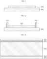
- FIG. 2 is a cross-sectional view schematically showing the current collector having the primer layer on the surface in the process of manufacturing the dry electrode according to an embodiment of the present disclosure.
- the current collector has the uncoated portion having a predetermined width inwards from each of two widthwise edges on one surface, and the primer layer is present between the uncoated portions.
- the primer layer may include a conductive material and a binder resin.
- the primer layer will be described in detail below.
- the dam is formed on the two widthwise sides of the primer layer to prevent the electrode powder from flowing down (S20).
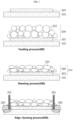
- the laser may reach the current collector 101 and the primer layer 102, causing damage to an unwanted area 200.
- FIGs. 3a and 3b are side and top views schematically showing the electrode having the dam 121 at the two widthwise ends of the primer layer 102 on one surface of the current collector 101 in the method for manufacturing the dry electrode according to an embodiment of the present disclosure, respectively.
- the dam 121 may be formed on at least part of the side of the primer layer 102, but may be preferably formed over the entire side of the primer layer for uniformity in the edge quality of the electrode.
- the width of the dam may be smaller than the width of the uncoated portion.
- the dam is preferably in close contact with the side of the primer layer without a gap to prevent the electrode powder from going in between the primer layer and the dam when coating the electrode powder in the following step.
- the dam may be formed with a height that is equal to or lower than the height of the electrode active portion.
- the electrode active portion is used to indicate a stack of the primer layer and the electrode active material layer.
- the dam plays a role in controlling the position to stay the electrode powder on the primer layer and prevent the electrode powder from bulging out from the primer layer when coating the electrode powder on the primer layer, and accordingly, preferably, the dam extends outward from the current collector surface and the height of the dam is higher than the height of the primer layer.
- the dam preferably includes any material that does not change the physical and chemical properties of the primer layer and the electrode powder when it contacts the primer layer and the electrode powder.
- the dam is not a component of the battery involved in electrochemical activity and may be used to help the electrode to have a predetermined shape when manufacturing the electrode. Accordingly, preferably, the dam does not cause damage to the electrode, and does not have any physical/chemical influence on the electrode materials such as the electrode active material.
- the dam may include at least one of an insulating polymer material or an inorganic material.
- the dam may include the insulating polymer material and the inorganic material in an amount of 90 wt% or more based on 100 wt% of the dam, or the dam may consist of the insulating polymer material and/or the inorganic material.
- the insulating polymer material may include, for example, polyethylene (PE), polypropylene (PP), polybutylene (PB), polystyrene (PS), polyethylene terephthalate (PET), natural rubber and synthetic rubber, but is not limited thereto.
- PE polyethylene
- PP polypropylene
- PB polybutylene
- PS polystyrene
- PET polyethylene terephthalate
- the inorganic material may include, without limitation, any inorganic material that is electrochemically stable without oxidation and/or reduction reaction in the operating voltage range (for example, 0 to 5V based on Li/Li+) of the battery.
- Non-limiting examples of the inorganic material may include at least one selected from BaTiO 3 , Pb(Zr,Ti)O 3 (PZT), Pb 1-x La x Zr 1-y Ti y O 3 (PLZT), PB(Mg 3 Nb 2/3 )O 3 -PbTiO 3 (PMN-PT), hafnia (HfO 2 ), SrTiO 3 , SnO 2 , CeO 2 , MgO, NiO, CaO, ZnO, ZrO 2 , Y 2 O 3 , Al 2 O 3 , TiO 2 and SiC, but is not limited thereto.
- FIG. 3a is a side view of the electrode having the dam at the two widthwise ends of the primer layer. Referring to FIG. 3a , it is confirmed that the height of the dam is higher than the height of the primer layer.
- FIG. 3b is a top view showing the primer layer and the dam on the surface of the current collector.
- the uncoated portion having the predetermined width is present at the two widthwise ends of the current collector, the primer layer is present between the uncoated portions, and the dam is disposed in close contact with the primer layer at the two ends of the primer layer.
- FIG. 3b schematically shows a long strip-shaped sheet manufactured by a roll-to-roll continuous process.
- the electrode may be cut at a predetermined interval and used as a unit electrode having a predetermined size, or may be wound together with a strip-shaped separator and a counter electrode to form an electrode assembly of a jellyroll structure.
- the width of the dam may be determined, taking into account the size of the electrode powder.
- the width of the dam may, for example, satisfy 0.80 d1 ⁇ the width of the dam ⁇ 1.20 d1.
- the electrode powder may have the particle size in a range between 0.1 and 1,000 ⁇ m.
- the average particle size (D 50 ) of the electrode powder may be from 10 ⁇ m to 500 ⁇ m, specifically from 15 ⁇ m to 200 ⁇ m, from 15 ⁇ m to 100 ⁇ m, or from 30 ⁇ m to 80 ⁇ m, for example, from 40 ⁇ m to 60 ⁇ m, or from 45 ⁇ m to 55 ⁇ m, or from 45 ⁇ m to 50 ⁇ m.
- the dam may have the width of up to 100 ⁇ m.
- the height of the dam may be determined, taking into account the height of the electrode active portion.
- the height of the dam may be preferably higher than the height of the primer layer. Additionally, considering the subsequent rolling process of the electrode active material layer, the height of the dam may be preferably lower than the height of the electrode active material layer.
- the dam may have the height of up to 50 ⁇ m.
- the width or height of the dam is not limited to the aforementioned range and may be set to an appropriate range, taking into account the width of the current collector, the width or height of the electrode active material layer, the particle size of the electrode powder, etc.
- the dam may be formed by coating a dam forming ink (a dam forming composition) on the side of the primer layer using a coater such as an inkjet printer.
- the dam is preferably formed in close contact with the side of the primer layer without a gap.
- the electrode powder is fed onto the primer layer surface (S30).
- the current collector having the primer layer and the dam is fed into the process of manufacturing the dry electrode by the roll-to-roll continuous process and the electrode powder is fed onto the surface of the primer layer through an electrode powder feeder 401 (the feeding process, 400).
- the electrode powder When coating the electrode powder, the space in which the electrode powder may be disposed is restricted by the dam, thus as a result, the electrode powder may be positioned on the surface of the primer layer without bulging out from the primer layer.
- FIG. 4 schematically shows the electrode active portion 111 in which the electrode powder is positioned on the surface of the primer layer without bulging out by the dam.
- the electrode powder feeder is not limited to a particular type and may include a screw feeder.
- the electrode powder applied to the current collector may undergo uniform thickness adjustment using a blade, and be fed into a press machine.
- the electrode powder is compressed to form the electrode active material layer of layered structure (S40).
- the step (S40) may be performed by applying the pressure to the electrode powder by a pair of sheeting rolls.
- the electrode powder is compressed by the applied pressure so the electrode powder particles are tightly packed to form the electrode active material layer, and compared to before the compression, the total volume (apparent volume) decreases and the density increases.
- the dam fixes the shape of the electrode active material layer at the two widthwise ends of the electrode active material layer, thereby preventing the electrode powder from being pressed out the primer layer or reducing the quantity of electrode powder pressed out.
- the electrode powder is pressed while passing between the pair of sheeting rolls 501 to form the electrode active material layer of layered structure.
- the pressing may be performed twice or more times, if necessary.
- two cylindrical rolls may be vertically arranged in parallel at a small interval, and the electrode may be placed between the rolls, brought into contact, and pressed by rotating the rolls in the opposite directions.
- the rolls may perform heating or cooling temperature adjustment.
- the temperature of the electrode powder and/or the electrode active material layer may be, for example, controlled in a range between 0°C and 200°C.
- the temperature control may be transmitted to the electrode powder and/or the electrode active material layer by the press rollers.
- the temperature may be higher than the melting point or glass transition temperature of a binder resin for the electrode, and more preferably, may be higher by 20°C or more than the melting point or glass transition temperature.
- the molding rate of the press forming may be usually from 0.1 to 20 m/min, or from 1 to 10 m/min.
- the press line pressure between rolls may be usually, for example, from 0.2 to 30 kN/cm, or from 0.5 to 10 kN/cm.
- the method may further include the step of trimming the side of the electrode active material layer.
- the method may be referred to as an edge cleaning process.
- the trimming may be performed to remove the electrode powder bulging out of the limited space of the dam when pressing in the above-described step and/or to make the side surface of the electrode active material layer less rough and even.
- the step (S50) may be performed to remove the electrode active material layer protruding out of the dam after the step (S40) is performed.
- the trimming may be performed by laser irradiation.
- the method used is not limited to laser irradiation and may include any method for trimming without causing damage to the electrode active material layer.
- the metal foil used as the current collector may deteriorate by laser irradiation, but in the process of manufacturing the dry electrode according to the present disclosure, due to the presence of the dam on the current collector surface, it may be possible to prevent damage to the current collector due to direct laser irradiation onto the current collector surface.
- Another means may be, for example, a knife type etching method.
- the knife type etching method may be, for example, performed by cutting a ragged electrode powder coating area using a blade and removing the cutout area through an air knife and a suction.
- the blade may be a rotating circular blade, but the present disclosure is not limited thereto.
- the laser irradiation may be performed on two sides of the sheet-type dry electrode.
- the laser irradiation may be performed first on one side, then the other side.
- the laser irradiation may be performed on the two sides at the same time.
- the laser irradiation may be performed on the two sides of the sheet-type dry electrode.
- the side of the electrode active material layer may be trimmed to prevent unevenness.
- the electrode powder refers to a powdery material including composite particles including an electrode active material and a binder resin for the electrode.
- the composite particles are formed by binding the electrode active material by the binder resin for the electrode.
- the electrode active material may be present in an amount of 80 wt% or more, or 90 wt% or more of the total weight of the electrode powder.
- the binder resin for the electrode may be included in an amount of 20 wt% or less, or 10 wt% or less of the total weight of the electrode powder.
- the electrode powder may further include a conductive material for the electrode.
- the conductive material for the electrode may be included in a range of 10 wt% or less based on 100 wt% of the electrode powder.
- the electrode powder may have an aspect ratio of from 0.5 to 1.0.
- the aspect ratio may refer to a ratio of the average long axis length to the average short axis length of the electrode powder, and in this instance, the average short axis length refers to the average length value in the axial direction having the shortest length of the electrode powder, and the average long axis length refers to the average length value in the axial direction having the longest length of the electrode powder.
- the aspect ratio of the composite particles satisfies the aforementioned range, it may have a beneficial effect on the electrode powder having sufficient flowability suitable for the process.
- the particle size of the electrode powder may be in a range between 0.1 and 1,000 ⁇ m.
- the average particle size (D 50 ) of the electrode powder may be in a range between 10 ⁇ m and 500 ⁇ m, specifically 15 ⁇ m and 200 ⁇ m, 15 ⁇ m and 100 ⁇ m, or 30 ⁇ m and 80 ⁇ m, for example 40 ⁇ m and 60 ⁇ m, or 45 ⁇ m and 55 ⁇ m, 45 ⁇ m and 50 ⁇ m.
- the average particle size (D 50 ) of the electrode powder may be in a range between 50 ⁇ m and 500 ⁇ m, or 50 ⁇ m and 100 ⁇ m.
- the present disclosure relates to a dry electrode obtained by the above-described method for manufacturing the dry electrode.
- the dry electrode includes a current collector, and an electrode active portion on at least one surface of the current collector.
- the electrode active portion includes a primer layer, and an electrode active material layer on the primer layer.
- the electrode active portion has the above-described dam on all or at least part of the side.
- the dam is preferably disposed in close contact with the side of the electrode active portion without a gap.
- the dam may be formed with the height that is equal to or lower than the electrode active portion.
- the height of the dam may be preferably lower than the height of the electrode active portion.
- the dry electrode has the electrode active portion including the primer layer and the electrode active material layer stacked on the surface of the current collector in a sequential order, and the dam having the predetermined thickness is disposed in close contact with the side of the electrode active portion without a gap.
- the electrode active material layer includes the electrode active material and the binder resin for the electrode.
- the electrode materials may be included in the form of the composite particles.
- the electrode active material layer may include the electrode powder in an amount of 95 wt% or more based on 100 wt% of the electrode active material layer. Meanwhile, the electrode active material layer may further include free electrode active material particles originating from the electrode powder and/or the binder resin for the electrode.
- the electrode active material layer may further include the conductive material for the electrode.
- the conductive material for the electrode may be conductive material particles for the electrode included in the electrode powder or free conductive material particles for the electrode.
- the electrode active material layer includes the electrode powder packed in a layered structure, and the electrode powder has pores defined by interstitial volume or space between the electrode powder particles, and has a porous property derived from this structure.
- the electrode active material layer preferably has the porosity of from 20 vol% to 40 vol% in view of electrolyte wetting, shape stability and ionic conductivity.
- the electrode powder when the dry electrode is used as a positive electrode, may include a positive electrode active material.
- the electrode powder when used as a negative electrode, may include a negative electrode active material.
- the negative electrode active material may include, for example, carbon such as nongraphitizing carbon, graphite-based carbon; metal composite oxide such as Li x Fe 2 O 3 (0 ⁇ x ⁇ 1), Li x WO 2 (0 ⁇ x ⁇ 1), Sn x Me 1-x Me' y O z (Me: Mn, Fe, Pb, Ge; Me': Al, B, P, Si, Groups 1, 2 and 3 elements in the periodic table, halogen; 0 ⁇ x ⁇ 1; 1 ⁇ y ⁇ 3; 1 ⁇ z ⁇ 8); lithium metals; lithium alloys; silicon-based alloys; tin-based alloys; silicon-based oxide such as SiO, SiO/C, SiO 2 ; metal oxide such as SnO, SnO 2 , PbO, PbO 2 , Pb 2 O 3 , Pb 3 O 4 , Sb 2 O 3 , Sb 2 O 4 , Sb 2 O 5 , GeO, GeO 2 , Bi 2 O 3 , Bi 2 O 4 , and Bi 2
- the conductive material for the electrode is not limited to a particular type and may include any material having conductive properties without causing any chemical change in the corresponding battery, for example, graphite such as natural graphite or artificial graphite; carbon black such as carbon black, acetylene black, Ketjen black, channel black, furnace black, lamp black, thermal black; conductive fibers such as carbon fibers or metal fibers; fluorocarbon; metal powder such as aluminum powder, nickel powder; conductive whiskers such as zinc oxide, potassium titanate; conductive metal oxide such as titanium oxide; a conductive materials such as polyphenylene derivatives, but specifically, to uniformly mix the electrode conductive material and improve conductivity, the conductive material for the electrode may include at least one selected from the group consisting of activated carbon, graphite, carbon black and carbon nanotubes, and more specifically, activated carbon.
- the binder resin for the electrode may include, without limitation, any type of binder resin used as binder materials for electrochemical devices, and may include, for example, diene-based polymer, acrylate-based polymer, fluorine-based polymer, styrene-based polymer or two or more of them.
- Examples of the diene-based polymer may include polymer including a monomer unit derived from conjugated diene such as butadiene and isoprene and its hydrogenated form.
- a ratio of the conjugated diene-derived monomer unit in the diene-based polymer may be usually 40 wt% or more, preferably 50 wt% or more, and more preferably 60 wt% or more.
- the diene-based polymer may include conjugated diene homopolymer such as polybutadiene or polyisoprene; aromatic vinyl-conjugated diene copolymer such as styrene-butadiene copolymer (SBR) with carboxyl modification; vinyl cyanide-conjugated diene copolymer such as acrylonitrile-butadiene copolymer (NBR); hydrogenated SBR, hydrogenated NBR.
- conjugated diene homopolymer such as polybutadiene or polyisoprene
- aromatic vinyl-conjugated diene copolymer such as styrene-butadiene copolymer (SBR) with carboxyl modification
- vinyl cyanide-conjugated diene copolymer such as acrylonitrile-butadiene copolymer (NBR); hydrogenated SBR, hydrogenated NBR.
- the styrene-based polymer may include polymer having a styrene monomer-derived repeating unit, for example, styrene homopolymer (polystyrene), styrene copolymer.
- styrene copolymer may include block copolymer such as styrene-ethylene-butadiene copolymer, styrene-butadiene-propylene copolymer, styrene-isoprene copolymer, styrene acrylate-n-butyl itaconate-methyl methacrylate-acrylonitrile copolymer, styrene acrylate-n-butyl itaconate-methyl methacrylate-acrylonitrile copolymer, styrene-butadiene block copolymer, styrene-butadiene-styrene ⁇ block copolymer, styrene-ethylene-butylene-styrene ⁇ block copolymer, styrene-isoprene ⁇ block copolymer, styrene-ethylene-propylene-styrene ⁇ block copoly
- Example of the acrylate-based polymer may include polymer including a monomer unit derived from acrylic acid ester and/or methacrylic acid ester.
- a ratio of the monomer unit derived from acrylic acid ester and/or methacrylic acid ester in the acrylate-based polymer may be usually 40 wt% or more, preferably 50 wt% or more, and more preferably 60 wt% or more.
- the acrylate-based polymer may include cross-linked acrylate-based polymer such as an acrylic acid 2-ethylhexyl-methacrylic acid-acrylonitrile-ethyleneglycoldimethacrylate copolymer, an acrylic acid 2-ethylhexyl-methacrylic acid-methacrylonitrile-diethyleneglycoldimethacylate copolymer, an acrylic acid 2-ethylhexyl-styrene-methacrylic acid-ethyleneglycoldimethacylate copolymer, a butyl acrylate-acrylonitrile-diethyleneglycoldimethacylate copolymer and a butyl acrylate-acrylic acid-trimethylolpropanetrimethacrylate copolymer; a copolymer of ethylene and (meth)acrylic acid ester such as an ethylene-methyl acrylate copolymer, an ethylene-methyl methacrylate copolymer, an ethylene-methyl
- the radically polymerizable monomer used in the graft polymer may include, for example, methyl methacrylate, acrylonitrile, methacrylic acid.
- the copolymer of ethylene and (meth)acrylic acid such as an ethylene-acrylic acid copolymer, an ethylene-methacrylic acid copolymer may be used as a dispersible binder.
- the fluorine-based polymer may include polyvinylidene fluoride (PVdF), polytetrafluoroethylene (PTFE) and polyvinylidene fluoride-based copolymer such as PVDF-HFP, specifically polytetrafluoroethylene (PTFE).
- PVdF polyvinylidene fluoride
- PTFE polytetrafluoroethylene
- PVDF-HFP polyvinylidene fluoride-based copolymer
- PVDF-HFP specifically polytetrafluoroethylene
- the positive electrode binder may include a fluorine-based copolymer.
- the positive electrode may include the fluorine-based copolymer, for example, PTFE, and more preferably 60 wt% or more of PTFE based on the total weight of the binder.
- the positive electrode binder may further include other fluorine-based copolymer than PTFE, a styrene-based copolymer, a polyolefin-based copolymer, polyethylene oxide (PEO), an acrylate-based copolymer.
- the negative electrode binder when the electrode is a negative electrode, may include at least one of diene-based polymer or styrene-based polymer and it may be included in an amount of 60 wt% or more based on the total weight of the binder.
- the negative electrode may include the styrene-butadiene block copolymer in an amount of 60 wt% or more based on the total weight of the binder.
- the negative electrode binder may further include a fluorine-based copolymer, a polyolefin-based copolymer, polyethylene oxide (PEO), an acrylate-based copolymer.
- the binder resin for the electrode may include diene-based polymer and cross-linked acrylate-based polymer since it is possible to obtain the active material layer having good binding to the current collector or good surface smoothness and manufacture the electrode for the electrochemical device with high capacitance and low internal resistance.
- the binder resin for the electrode is not limited to a particular shape, but a particulate shape is preferred since the binding performance is good and it is possible to suppress the decline in capacitance of the manufactured electrode or degradation over the repeated charges/discharges.
- the particulate binder resin for the electrode may include, for example, dispersible binder particles dispersed in water like latex, or powder obtained by drying the dispersion.
- the particulate binder may be preferably included in the negative electrode.
- the electrode active material layer may further include fillers to suppress the expansion of the electrode active material layer, and the fillers are not limited to a particular type and may include any fibrous material that does not cause any chemical change in the corresponding battery, for example, olefin-based polymer such as polyethylene, polypropylene; and fibrous materials such as glass fibers, carbon fibers.
- olefin-based polymer such as polyethylene, polypropylene
- fibrous materials such as glass fibers, carbon fibers.
- the primer layer includes a binder resin for the primer layer and a conductive material for the primer layer, and optionally a dispersant.
- the binder resin for the primer layer may include, without limitation, any known binder used in the primer layer.
- the binder resin for the primer layer may include, for example, styrene butadiene rubber (SBR), butadiene rubber (BR), nitrile butadiene rubber (NBR), styrene butadiene styrene block polymer (SBS), styrene ethylene butadiene block polymer (SEB), styrene-(styrene butadiene)-styrene block polymer, natural rubber (NR), isoprene rubber (IR), ethylene-propylene-diene terpolymer (EPDM), poly(ethylene-co-propylene-co-5-methylene-2-norbornene, polytetrafluoroethylene (PTFE), polyvinylidene fluoride, polyvinyl chloride, polyvinylidene fluoride-co-hexafluoropropylene, polyvinylidene fluoride-co-trichloroethylene, polymethylmethacrylate, polyeth
- the binder may include styrene butadiene rubber (SBR), nitrile butadiene rubber (NBR), polymethylmethacrylate, polyethylhexylacrylate, polybutylacrylate or a mixture thereof.
- SBR styrene butadiene rubber
- NBR nitrile butadiene rubber
- polymethylmethacrylate polyethylhexylacrylate
- polybutylacrylate or a mixture thereof.
- the binder resin for the primer layer may have the glass transition temperature of 45°C or less to ensure time-dependent stability of the primer layer.
- the binder resin for the primer layer may include styrene butadiene rubber (SBR) having the glass transition temperature (Tg) of from -40°C to 45°C, nitrile butadiene rubber (NBR) having the glass transition temperature (Tg) of from -40°C to 45°C or a mixture thereof.
- SBR styrene butadiene rubber
- NBR nitrile butadiene rubber
- the conductive material for the primer layer is not limited to a particular type and may include any material having conductive properties without causing any chemical change in the corresponding battery, for example, graphite such as natural graphite or artificial graphite; a carbon black-based carbon compound such as carbon black, acetylene black, Ketjen black, channel black, furnace black, lamp black, thermal black; conductive fibers such as carbon fibers or metal fibers; fluorocarbon; metal powder such as aluminum powder, nickel powder; conductive whiskers such as zinc oxide, potassium titanate; conductive metal oxide such as titanium oxide; conductive materials such as polyphenylene derivatives, but specifically, to uniformly mix the conductive material and improve conductivity, the conductive material may include activated carbon, graphite, carbon black, carbon nanotubes or a mixture thereof, and more specifically, activated carbon.
- graphite such as natural graphite or artificial graphite
- a carbon black-based carbon compound such as carbon black, acetylene black, Ketjen black, channel black,
- the conductive material for the primer layer may include conductive materials having the specific surface area of from 30 m 2 /g to 1,400 m 2 /g and a spherical shape.
- the size of primary particles of the spherical conductive material may be, for example, from 10 nm to 100 nm, specifically from 15 nm to 70 nm.
- the conductive material for the primer layer may include conductive materials of tubular shape having the specific surface area of from 10 m 2 /g to 400 m 2 /g.
- the tubular conductive material may have a diameter of from 0.1 to 3 nm, specifically from 0.3 to 1.5 nm in cross section in a direction perpendicular to the length direction.
- the primer layer may include the above-described composition, and its thickness may be from 300 nm to 1.5 ⁇ m, specifically from 700 nm to 1.3 ⁇ m, but is not limited thereto.
- the electrode powder may be manufactured by a method including the steps of mixing the electrode active material and the binder resin for the electrode with a dispersion medium to prepare a slurry; and spray drying the slurry.
- the electrode active material and the electrode binder, and optionally the conductive material or an additive are dispersed or dissolved in the dispersion medium (the solvent for the negative electrode binder) to obtain the slurry in which the electrode conductive material and/or the additive is dispersed or dissolved together with the electrode active material and the electrode binder.
- the dispersion medium the solvent for the negative electrode binder
- the dispersion medium used to obtain the slurry is, the most suitably, water, but an organic solvent may be used.
- the organic solvent may include, for example, alkylalcohols such as methylalcohol, ethylalcohol, propylalcohol; alkylketones such as acetone, methylethylketone; ethers such as tetrahydrofuran, dioxane, diglyme; amides such as diethylformamide, dimethylacetoamide, N-methyl-2-pyrrolidone (hereinafter referred to as NMP), dimethylimidazolidinone; sulfur-based solvents such as dimethylsulfoxide, sulfolane, but alcohols are preferred.
- alkylalcohols such as methylalcohol, ethylalcohol, propylalcohol
- alkylketones such as acetone, methylethylketone
- ethers such as t
- the drying rate may increase during the flowable assembly. Additionally, since the dispersion or dissolution of the negative electrode binder may change, the viscosity or flowability of the slurry may be adjusted according to the amount or type of the dispersion medium, thereby improving the production efficiency.
- the dispersion medium used to prepare the slurry may be present in such an amount that the solid concentration of the slurry is usually in a range between 1 and 50 wt%, or 5 and 50 wt%, or 10 and 30 wt%.
- the method or order of dispersing or dissolving the electrode active material and the binder resin for the electrode in the dispersion medium is not particularly limited, and for example, the electrode active material and the electrode binder may be added to the dispersion medium and mixed up, or the electrode binder may be dissolved or dispersed in the dispersion medium, then the electrode active material may be added and mixed all together.
- the slurry includes the conductive material and/or the additive, when feeding the electrode active material, these components may be fed.
- the mixing means may include, for example, a ball mill, a sand mill, a bead mill, a pigment dispersion machine, a stone mill, an ultrasonic dispersion machine, a homogenizer and a planetary mixer.
- the mixing may be, for example, performed in a range between room temperature and 80°C for 10 minutes to a few hours.
- the spray drying method is a method that dries the slurry while spraying the slurry in hot air.
- a typical example of a device using the spray drying method may be an atomizer.
- the rotary atomizer feeds the slurry into almost the center of the disc that rotates at high speed, urges the slurry to the periphery of the disc by the centrifugal force of the disc to create mist and dries it.
- the rotation rate of the disc relies on the size of the disc, but is usually from 5,000 rpm to 35,000 rpm, and preferably from 15,000 rpm to 30,000 rpm. Meanwhile, the pressurized atomizer applies the pressure to the slurry to spurt a mist through a nozzle and dries it.
- the temperature of the slurry being sprayed is usually room temperature, but may be equal to or higher than room temperature by heating.
- the hot air temperature is usually from 80°C to 250°C, preferably from 100°C to 200°C.
- the hot air suction method is not limited to a particular method, and may include, for example, a method of cocurrent flow of hot air and spray direction in the horizontal direction, a method of spraying from a drying tower top to cause it fall together with hot air, a method of countercurrent contact between sprayed droplets and hot air, a method of cocurrent flow of sprayed droplets and hot air, then fall by gravity and countercurrent contact.
- thermal treatment may be optionally performed to cure the surface of the result obtained by the spray drying, i.e., the electrode powder, and in this instance, the thermal treatment temperature may be usually from 80°C to 300°C.
- the present disclosure provides a secondary battery including a battery case (a cylindrical case, a prismatic case, a pouch, etc.) accommodating an electrode assembly including the electrode and the separator obtained by the above-described method together with a lithium containing nonaqueous electrolyte, and an energy storage system including the secondary battery as a unit cell.
- a battery case a cylindrical case, a prismatic case, a pouch, etc.
- an electrode assembly including the electrode and the separator obtained by the above-described method together with a lithium containing nonaqueous electrolyte
- an energy storage system including the secondary battery as a unit cell.
- at least one of the positive electrode or the negative electrode may be the electrode obtained by the above-described method.
- the separator may include a porous polymer film commonly used as separators, for example, a porous polymer film of polyolefin-based polymer such as ethylene homopolymer, propylene homopolymer, ethylene/butene copolymer, ethylene/hexene copolymer and ethylene/methacrylate copolymer as used singly or in stack. Additionally, an insulation thin film having high ion permeability and mechanical strength may be used.
- the separator may include a safety reinforced separator (SRS) having a thin coating of ceramic material on the separator surface.
- the separator may include commonly used porous nonwoven fabrics, for example, nonwoven fabrics of high melting point glass fibers, polyethyleneterephthalate fibers, but is not limited thereto.
- the electrolyte solution includes a lithium salt as an electrolyte and an organic solvent to dissolve it.
- the lithium salt may include, without limitation, those commonly used in electrolyte solutions for secondary batteries, and for example, an anion of the lithium salt may include at least one selected from the group consisting of F - , Cl - , I - , NO 3 - , N(CN) 2 - , BF 4 - , ClO 4 - , PF 6 - , (CF 3 ) 2 PF 4 - , (CF 3 ) 3 PF 3 - , (CF 3 ) 4 PF 2 - , (CF 3 ) 5 PF - , (CF 3 ) 6 P - , CF 3 SO 3 - , CF 3 CF 2 SO 3 - , (CF 3 SO 2 ) 2 N - , (FSO 2 ) 2 N - , CF 3 CF 2 (CF 3 ) 2 CO - , (CF 3 SO 2 ) 2 CH - , (SF 5 ) 3 C - , (CF 3 SO 2 ) 3 C
- the organic solvent included in the electrolyte solution may include any commonly used organic solvent without limitation, and typically may include at least one selected from the group consisting of propylene carbonate, ethylene carbonate, diethylcarbonate, dimethylcarbonate, ethylmethylcarbonate, methylpropylcarbonate, dipropylcarbonate, dimethylsulfoxide, acetonitrile, dimethoxyethane, diethoxyethane, vinylenecarbonate, sulfolane, gamma-butyrolactone, propylene sulfite and tetrahydrofuran.
- propylene carbonate ethylene carbonate, diethylcarbonate, dimethylcarbonate, ethylmethylcarbonate, methylpropylcarbonate, dipropylcarbonate, dimethylsulfoxide, acetonitrile, dimethoxyethane, diethoxyethane, vinylenecarbonate, sulfolane, gamma-butyrolactone,
- cyclic carbonate such as ethylenecarbonate and propylenecarbonate is a high viscosity organic solvent and has a high dielectric constant, so it dissolves the lithium salt in the electrolyte well, and more preferably, when the cyclic carbonate is mixed with low viscosity and low dielectric constant linear carbonate such as dimethylcarbonate and diethylcarbonate at an optimal ratio, the electrolyte solution having high electrical conductivity may be prepared.
- the electrolyte solution stored according to the present disclosure may further include an additive such as an overvoltage preventing agent included in the commonly used electrolyte solutions.
- the lithium secondary battery according to an embodiment of the present disclosure may be completed by placing the positive electrode and the negative electrode with the separator interposed between them to form the electrode assembly, putting the electrode assembly in, for example, a pouch, a cylindrical battery case or a prismatic battery case, and injecting the electrolyte.
- the lithium secondary battery may be completed by stacking the electrode assembly and immersing it in the electrolyte solution, placing the obtained result in the battery case, and sealing the battery case.
Landscapes
- Chemical & Material Sciences (AREA)
- Chemical Kinetics & Catalysis (AREA)
- Electrochemistry (AREA)
- General Chemical & Material Sciences (AREA)
- Engineering & Computer Science (AREA)
- Manufacturing & Machinery (AREA)
- Materials Engineering (AREA)
- Composite Materials (AREA)
- Battery Electrode And Active Subsutance (AREA)
- Electric Double-Layer Capacitors Or The Like (AREA)
- Cell Electrode Carriers And Collectors (AREA)
Applications Claiming Priority (2)
| Application Number | Priority Date | Filing Date | Title |
|---|---|---|---|
| KR20220185089 | 2022-12-26 | ||
| PCT/KR2023/021599 WO2024144216A1 (fr) | 2022-12-26 | 2023-12-26 | Procédé de fabrication d'électrode sèche et système de fabrication d'électrode sèche |
Publications (2)
| Publication Number | Publication Date |
|---|---|
| EP4571867A1 true EP4571867A1 (fr) | 2025-06-18 |
| EP4571867A4 EP4571867A4 (fr) | 2026-03-18 |
Family
ID=91718401
Family Applications (1)
| Application Number | Title | Priority Date | Filing Date |
|---|---|---|---|
| EP23912891.1A Pending EP4571867A4 (fr) | 2022-12-26 | 2023-12-26 | Procédé de fabrication d'électrode sèche et système de fabrication d'électrode sèche |
Country Status (5)
| Country | Link |
|---|---|
| EP (1) | EP4571867A4 (fr) |
| JP (1) | JP2026500422A (fr) |
| KR (1) | KR20240102909A (fr) |
| CN (1) | CN118805267A (fr) |
| WO (1) | WO2024144216A1 (fr) |
Families Citing this family (2)
| Publication number | Priority date | Publication date | Assignee | Title |
|---|---|---|---|---|
| CN120615241A (zh) * | 2023-11-15 | 2025-09-09 | 株式会社Lg新能源 | 干电极用集流体、包括其的电极和包括其的锂二次电池 |
| KR20260020704A (ko) | 2024-08-05 | 2026-02-12 | 한국기계연구원 | 건식 전극 제조장치 및 이를 이용한 건식 전극 제조방법 |
Family Cites Families (8)
| Publication number | Priority date | Publication date | Assignee | Title |
|---|---|---|---|---|
| US7097673B2 (en) * | 2001-06-07 | 2006-08-29 | 3M Innovative Properties Company | Coating edge control |
| FR2982082B1 (fr) * | 2011-11-02 | 2013-11-22 | Fabien Gaben | Procede de fabrication de batteries en couches minces entierement solides |
| US20200144591A1 (en) * | 2015-09-01 | 2020-05-07 | Worcester Polytechnic Institute | Adhesive interlayer for battery electrode through dry manufacturing |
| KR20180001229A (ko) * | 2016-06-27 | 2018-01-04 | 삼성에스디아이 주식회사 | 이차 전지의 제조 방법 및 이를 이용한 이차 전지 |
| US11276846B2 (en) * | 2017-09-25 | 2022-03-15 | Lg Energy Solution, Ltd. | Method for manufacturing electrode for secondary battery and electrode manufactured thereby |
| CN114207864A (zh) * | 2019-01-16 | 2022-03-18 | 麦斯韦尔技术股份有限公司 | 用于制造干电极的系统和方法 |
| CN110911637B (zh) * | 2019-12-05 | 2021-07-30 | 东莞塔菲尔新能源科技有限公司 | 一种负极片、其制备方法和锂离子电池 |
| JP7834742B2 (ja) * | 2020-10-21 | 2026-03-24 | エルジー エナジー ソリューション リミテッド | 二次電池用乾式電極を製造するための電極用粉体、その製造方法、それを使用した乾式電極の製造方法 |
-
2023
- 2023-12-26 JP JP2025537565A patent/JP2026500422A/ja active Pending
- 2023-12-26 KR KR1020230191445A patent/KR20240102909A/ko active Pending
- 2023-12-26 WO PCT/KR2023/021599 patent/WO2024144216A1/fr not_active Ceased
- 2023-12-26 EP EP23912891.1A patent/EP4571867A4/fr active Pending
- 2023-12-26 CN CN202380024592.8A patent/CN118805267A/zh active Pending
Also Published As
| Publication number | Publication date |
|---|---|
| WO2024144216A1 (fr) | 2024-07-04 |
| CN118805267A (zh) | 2024-10-18 |
| EP4571867A4 (fr) | 2026-03-18 |
| KR20240102909A (ko) | 2024-07-03 |
| JP2026500422A (ja) | 2026-01-06 |
Similar Documents
| Publication | Publication Date | Title |
|---|---|---|
| KR101471795B1 (ko) | 비수 전해액 리튬 2차 전지 | |
| KR102682401B1 (ko) | 전극 및 이를 포함하는 전기화학소자 | |
| US20150236343A1 (en) | Coated electrodes for lithium batteries | |
| JP5800208B2 (ja) | 非水電解質二次電池 | |
| CN108475774A (zh) | 其上形成有双保护层的锂二次电池用负极和包含其的锂二次电池 | |
| ES2986501T3 (es) | Material activo de electrodo negativo para batería secundaria de litio, y electrodo negativo y batería secundaria de litio que incluyen el mismo | |
| EP4571867A1 (fr) | Procédé de fabrication d'électrode sèche et système de fabrication d'électrode sèche | |
| EP2044639A2 (fr) | Batteries, électrodes destinées à des batteries et leurs procédés de fabrication | |
| KR20200030518A (ko) | 전지의 제조 방법 | |
| KR20190065153A (ko) | 이차전지용 전극의 제조방법 | |
| KR20200076076A (ko) | 마그네슘 보호층을 포함하는 음극, 이의 제조방법 및 이를 포함하는 리튬 이차전지 | |
| KR20240101497A (ko) | 전기화학소자용 음극 | |
| JP2014157661A (ja) | 電気化学素子正極用複合粒子の製造方法 | |
| CN101536217B (zh) | 非水电解质二次电池用电极及使用该电极的非水电解质二次电池 | |
| US20220328931A1 (en) | Separator for Secondary Battery, Method for Manufacturing the Same and Lithium Secondary Battery Containing the Same | |
| JP4992203B2 (ja) | リチウムイオン二次電池 | |
| JP2019071167A (ja) | リチウムイオン二次電池 | |
| EP4471905A1 (fr) | Granules composites comprenant un matériau d'électrode et électrode pour dispositif électrochimique les comprenant | |
| US20230130295A1 (en) | Negative electrode and battery | |
| JP5017769B2 (ja) | 非水電解質二次電池 | |
| JP2024077131A (ja) | 非水二次電池及び非水二次電池の製造方法 | |
| JP2003187787A (ja) | リチウム電池用正極の製造方法 | |
| KR102954854B1 (ko) | 전극의 건식 제조 방법 | |
| KR102852031B1 (ko) | 전극, 이의 제조방법, 및 이를 포함하는 전기화학소자 | |
| CN118476067A (zh) | 电极和包括该电极的电化学装置 |
Legal Events
| Date | Code | Title | Description |
|---|---|---|---|
| STAA | Information on the status of an ep patent application or granted ep patent |
Free format text: STATUS: THE INTERNATIONAL PUBLICATION HAS BEEN MADE |
|
| PUAI | Public reference made under article 153(3) epc to a published international application that has entered the european phase |
Free format text: ORIGINAL CODE: 0009012 |
|
| STAA | Information on the status of an ep patent application or granted ep patent |
Free format text: STATUS: REQUEST FOR EXAMINATION WAS MADE |
|
| 17P | Request for examination filed |
Effective date: 20250310 |
|
| AK | Designated contracting states |
Kind code of ref document: A1 Designated state(s): AL AT BE BG CH CY CZ DE DK EE ES FI FR GB GR HR HU IE IS IT LI LT LU LV MC ME MK MT NL NO PL PT RO RS SE SI SK SM TR |
|
| A4 | Supplementary search report drawn up and despatched |
Effective date: 20260213 |
|
| RIC1 | Information provided on ipc code assigned before grant |
Ipc: H01M 4/04 20060101AFI20260209BHEP Ipc: H01M 4/139 20100101ALI20260209BHEP Ipc: H01M 4/66 20060101ALI20260209BHEP Ipc: H01M 4/62 20060101ALI20260209BHEP Ipc: H01M 50/474 20210101ALI20260209BHEP Ipc: H01M 4/13 20100101ALI20260209BHEP |
|
| DAV | Request for validation of the european patent (deleted) | ||
| DAX | Request for extension of the european patent (deleted) |