EP4572040A1 - Lichtquelle mit einem resonanzhohlraum mit verteilter rückkopplung und verfahren zur herstellung einer solchen lichtquelle - Google Patents
Lichtquelle mit einem resonanzhohlraum mit verteilter rückkopplung und verfahren zur herstellung einer solchen lichtquelle Download PDFInfo
- Publication number
- EP4572040A1 EP4572040A1 EP24218706.0A EP24218706A EP4572040A1 EP 4572040 A1 EP4572040 A1 EP 4572040A1 EP 24218706 A EP24218706 A EP 24218706A EP 4572040 A1 EP4572040 A1 EP 4572040A1
- Authority
- EP
- European Patent Office
- Prior art keywords
- substrate
- stack
- layers
- layer
- resonant
- Prior art date
- Legal status (The legal status is an assumption and is not a legal conclusion. Google has not performed a legal analysis and makes no representation as to the accuracy of the status listed.)
- Pending
Links
Images


Classifications
-
- H—ELECTRICITY
- H01—ELECTRIC ELEMENTS
- H01S—DEVICES USING THE PROCESS OF LIGHT AMPLIFICATION BY STIMULATED EMISSION OF RADIATION [LASER] TO AMPLIFY OR GENERATE LIGHT; DEVICES USING STIMULATED EMISSION OF ELECTROMAGNETIC RADIATION IN WAVE RANGES OTHER THAN OPTICAL
- H01S5/00—Semiconductor lasers
- H01S5/10—Construction or shape of the optical resonator, e.g. extended or external cavity, coupled cavities, bent-guide, varying width, thickness or composition of the active region
- H01S5/12—Construction or shape of the optical resonator, e.g. extended or external cavity, coupled cavities, bent-guide, varying width, thickness or composition of the active region the resonator having a periodic structure, e.g. in distributed feedback [DFB] lasers
- H01S5/1237—Lateral grating, i.e. grating only adjacent ridge or mesa
-
- H—ELECTRICITY
- H01—ELECTRIC ELEMENTS
- H01S—DEVICES USING THE PROCESS OF LIGHT AMPLIFICATION BY STIMULATED EMISSION OF RADIATION [LASER] TO AMPLIFY OR GENERATE LIGHT; DEVICES USING STIMULATED EMISSION OF ELECTROMAGNETIC RADIATION IN WAVE RANGES OTHER THAN OPTICAL
- H01S5/00—Semiconductor lasers
- H01S5/02—Structural details or components not essential to laser action
- H01S5/0206—Substrates, e.g. growth, shape, material, removal or bonding
- H01S5/021—Silicon based substrates
-
- H—ELECTRICITY
- H01—ELECTRIC ELEMENTS
- H01S—DEVICES USING THE PROCESS OF LIGHT AMPLIFICATION BY STIMULATED EMISSION OF RADIATION [LASER] TO AMPLIFY OR GENERATE LIGHT; DEVICES USING STIMULATED EMISSION OF ELECTROMAGNETIC RADIATION IN WAVE RANGES OTHER THAN OPTICAL
- H01S5/00—Semiconductor lasers
- H01S5/10—Construction or shape of the optical resonator, e.g. extended or external cavity, coupled cavities, bent-guide, varying width, thickness or composition of the active region
- H01S5/1053—Comprising an active region having a varying composition or cross-section in a specific direction
- H01S5/1064—Comprising an active region having a varying composition or cross-section in a specific direction varying width along the optical axis
-
- H—ELECTRICITY
- H01—ELECTRIC ELEMENTS
- H01S—DEVICES USING THE PROCESS OF LIGHT AMPLIFICATION BY STIMULATED EMISSION OF RADIATION [LASER] TO AMPLIFY OR GENERATE LIGHT; DEVICES USING STIMULATED EMISSION OF ELECTROMAGNETIC RADIATION IN WAVE RANGES OTHER THAN OPTICAL
- H01S5/00—Semiconductor lasers
- H01S5/20—Structure or shape of the semiconductor body to guide the optical wave ; Confining structures perpendicular to the optical axis, e.g. index or gain guiding, stripe geometry, broad area lasers, gain tailoring, transverse or lateral reflectors, special cladding structures, MQW barrier reflection layers
- H01S5/2004—Confining in the direction perpendicular to the layer structure
- H01S5/2018—Optical confinement, e.g. absorbing-, reflecting- or waveguide-layers
-
- H—ELECTRICITY
- H01—ELECTRIC ELEMENTS
- H01S—DEVICES USING THE PROCESS OF LIGHT AMPLIFICATION BY STIMULATED EMISSION OF RADIATION [LASER] TO AMPLIFY OR GENERATE LIGHT; DEVICES USING STIMULATED EMISSION OF ELECTROMAGNETIC RADIATION IN WAVE RANGES OTHER THAN OPTICAL
- H01S5/00—Semiconductor lasers
- H01S5/20—Structure or shape of the semiconductor body to guide the optical wave ; Confining structures perpendicular to the optical axis, e.g. index or gain guiding, stripe geometry, broad area lasers, gain tailoring, transverse or lateral reflectors, special cladding structures, MQW barrier reflection layers
- H01S5/2054—Methods of obtaining the confinement
- H01S5/2081—Methods of obtaining the confinement using special etching techniques
-
- H—ELECTRICITY
- H01—ELECTRIC ELEMENTS
- H01S—DEVICES USING THE PROCESS OF LIGHT AMPLIFICATION BY STIMULATED EMISSION OF RADIATION [LASER] TO AMPLIFY OR GENERATE LIGHT; DEVICES USING STIMULATED EMISSION OF ELECTROMAGNETIC RADIATION IN WAVE RANGES OTHER THAN OPTICAL
- H01S5/00—Semiconductor lasers
- H01S5/20—Structure or shape of the semiconductor body to guide the optical wave ; Confining structures perpendicular to the optical axis, e.g. index or gain guiding, stripe geometry, broad area lasers, gain tailoring, transverse or lateral reflectors, special cladding structures, MQW barrier reflection layers
- H01S5/22—Structure or shape of the semiconductor body to guide the optical wave ; Confining structures perpendicular to the optical axis, e.g. index or gain guiding, stripe geometry, broad area lasers, gain tailoring, transverse or lateral reflectors, special cladding structures, MQW barrier reflection layers having a ridge or stripe structure
- H01S5/2205—Structure or shape of the semiconductor body to guide the optical wave ; Confining structures perpendicular to the optical axis, e.g. index or gain guiding, stripe geometry, broad area lasers, gain tailoring, transverse or lateral reflectors, special cladding structures, MQW barrier reflection layers having a ridge or stripe structure comprising special burying or current confinement layers
-
- H—ELECTRICITY
- H01—ELECTRIC ELEMENTS
- H01S—DEVICES USING THE PROCESS OF LIGHT AMPLIFICATION BY STIMULATED EMISSION OF RADIATION [LASER] TO AMPLIFY OR GENERATE LIGHT; DEVICES USING STIMULATED EMISSION OF ELECTROMAGNETIC RADIATION IN WAVE RANGES OTHER THAN OPTICAL
- H01S2301/00—Functional characteristics
- H01S2301/17—Semiconductor lasers comprising special layers
- H01S2301/176—Specific passivation layers on surfaces other than the emission facet
-
- H—ELECTRICITY
- H01—ELECTRIC ELEMENTS
- H01S—DEVICES USING THE PROCESS OF LIGHT AMPLIFICATION BY STIMULATED EMISSION OF RADIATION [LASER] TO AMPLIFY OR GENERATE LIGHT; DEVICES USING STIMULATED EMISSION OF ELECTROMAGNETIC RADIATION IN WAVE RANGES OTHER THAN OPTICAL
- H01S5/00—Semiconductor lasers
- H01S5/02—Structural details or components not essential to laser action
- H01S5/0206—Substrates, e.g. growth, shape, material, removal or bonding
- H01S5/0215—Bonding to the substrate
- H01S5/0216—Bonding to the substrate using an intermediate compound, e.g. a glue or solder
-
- H—ELECTRICITY
- H01—ELECTRIC ELEMENTS
- H01S—DEVICES USING THE PROCESS OF LIGHT AMPLIFICATION BY STIMULATED EMISSION OF RADIATION [LASER] TO AMPLIFY OR GENERATE LIGHT; DEVICES USING STIMULATED EMISSION OF ELECTROMAGNETIC RADIATION IN WAVE RANGES OTHER THAN OPTICAL
- H01S5/00—Semiconductor lasers
- H01S5/04—Processes or apparatus for excitation, e.g. pumping, e.g. by electron beams
- H01S5/042—Electrical excitation ; Circuits therefor
- H01S5/0425—Electrodes, e.g. characterised by the structure
- H01S5/04252—Electrodes, e.g. characterised by the structure characterised by the material
- H01S5/04253—Electrodes, e.g. characterised by the structure characterised by the material having specific optical properties, e.g. transparent electrodes
-
- H—ELECTRICITY
- H01—ELECTRIC ELEMENTS
- H01S—DEVICES USING THE PROCESS OF LIGHT AMPLIFICATION BY STIMULATED EMISSION OF RADIATION [LASER] TO AMPLIFY OR GENERATE LIGHT; DEVICES USING STIMULATED EMISSION OF ELECTROMAGNETIC RADIATION IN WAVE RANGES OTHER THAN OPTICAL
- H01S5/00—Semiconductor lasers
- H01S5/04—Processes or apparatus for excitation, e.g. pumping, e.g. by electron beams
- H01S5/042—Electrical excitation ; Circuits therefor
- H01S5/0425—Electrodes, e.g. characterised by the structure
- H01S5/04256—Electrodes, e.g. characterised by the structure characterised by the configuration
- H01S5/04257—Electrodes, e.g. characterised by the structure characterised by the configuration having positive and negative electrodes on the same side of the substrate
-
- H—ELECTRICITY
- H01—ELECTRIC ELEMENTS
- H01S—DEVICES USING THE PROCESS OF LIGHT AMPLIFICATION BY STIMULATED EMISSION OF RADIATION [LASER] TO AMPLIFY OR GENERATE LIGHT; DEVICES USING STIMULATED EMISSION OF ELECTROMAGNETIC RADIATION IN WAVE RANGES OTHER THAN OPTICAL
- H01S5/00—Semiconductor lasers
- H01S5/10—Construction or shape of the optical resonator, e.g. extended or external cavity, coupled cavities, bent-guide, varying width, thickness or composition of the active region
- H01S5/1039—Details on the cavity length
-
- H—ELECTRICITY
- H01—ELECTRIC ELEMENTS
- H01S—DEVICES USING THE PROCESS OF LIGHT AMPLIFICATION BY STIMULATED EMISSION OF RADIATION [LASER] TO AMPLIFY OR GENERATE LIGHT; DEVICES USING STIMULATED EMISSION OF ELECTROMAGNETIC RADIATION IN WAVE RANGES OTHER THAN OPTICAL
- H01S5/00—Semiconductor lasers
- H01S5/10—Construction or shape of the optical resonator, e.g. extended or external cavity, coupled cavities, bent-guide, varying width, thickness or composition of the active region
- H01S5/12—Construction or shape of the optical resonator, e.g. extended or external cavity, coupled cavities, bent-guide, varying width, thickness or composition of the active region the resonator having a periodic structure, e.g. in distributed feedback [DFB] lasers
- H01S5/1231—Grating growth or overgrowth details
-
- H—ELECTRICITY
- H01—ELECTRIC ELEMENTS
- H01S—DEVICES USING THE PROCESS OF LIGHT AMPLIFICATION BY STIMULATED EMISSION OF RADIATION [LASER] TO AMPLIFY OR GENERATE LIGHT; DEVICES USING STIMULATED EMISSION OF ELECTROMAGNETIC RADIATION IN WAVE RANGES OTHER THAN OPTICAL
- H01S5/00—Semiconductor lasers
- H01S5/20—Structure or shape of the semiconductor body to guide the optical wave ; Confining structures perpendicular to the optical axis, e.g. index or gain guiding, stripe geometry, broad area lasers, gain tailoring, transverse or lateral reflectors, special cladding structures, MQW barrier reflection layers
- H01S5/2004—Confining in the direction perpendicular to the layer structure
- H01S5/2018—Optical confinement, e.g. absorbing-, reflecting- or waveguide-layers
- H01S5/2027—Reflecting region or layer, parallel to the active layer, e.g. to modify propagation of the mode in the laser or to influence transverse modes
-
- H—ELECTRICITY
- H01—ELECTRIC ELEMENTS
- H01S—DEVICES USING THE PROCESS OF LIGHT AMPLIFICATION BY STIMULATED EMISSION OF RADIATION [LASER] TO AMPLIFY OR GENERATE LIGHT; DEVICES USING STIMULATED EMISSION OF ELECTROMAGNETIC RADIATION IN WAVE RANGES OTHER THAN OPTICAL
- H01S5/00—Semiconductor lasers
- H01S5/20—Structure or shape of the semiconductor body to guide the optical wave ; Confining structures perpendicular to the optical axis, e.g. index or gain guiding, stripe geometry, broad area lasers, gain tailoring, transverse or lateral reflectors, special cladding structures, MQW barrier reflection layers
- H01S5/22—Structure or shape of the semiconductor body to guide the optical wave ; Confining structures perpendicular to the optical axis, e.g. index or gain guiding, stripe geometry, broad area lasers, gain tailoring, transverse or lateral reflectors, special cladding structures, MQW barrier reflection layers having a ridge or stripe structure
-
- H—ELECTRICITY
- H01—ELECTRIC ELEMENTS
- H01S—DEVICES USING THE PROCESS OF LIGHT AMPLIFICATION BY STIMULATED EMISSION OF RADIATION [LASER] TO AMPLIFY OR GENERATE LIGHT; DEVICES USING STIMULATED EMISSION OF ELECTROMAGNETIC RADIATION IN WAVE RANGES OTHER THAN OPTICAL
- H01S5/00—Semiconductor lasers
- H01S5/20—Structure or shape of the semiconductor body to guide the optical wave ; Confining structures perpendicular to the optical axis, e.g. index or gain guiding, stripe geometry, broad area lasers, gain tailoring, transverse or lateral reflectors, special cladding structures, MQW barrier reflection layers
- H01S5/22—Structure or shape of the semiconductor body to guide the optical wave ; Confining structures perpendicular to the optical axis, e.g. index or gain guiding, stripe geometry, broad area lasers, gain tailoring, transverse or lateral reflectors, special cladding structures, MQW barrier reflection layers having a ridge or stripe structure
- H01S5/2205—Structure or shape of the semiconductor body to guide the optical wave ; Confining structures perpendicular to the optical axis, e.g. index or gain guiding, stripe geometry, broad area lasers, gain tailoring, transverse or lateral reflectors, special cladding structures, MQW barrier reflection layers having a ridge or stripe structure comprising special burying or current confinement layers
- H01S5/2218—Structure or shape of the semiconductor body to guide the optical wave ; Confining structures perpendicular to the optical axis, e.g. index or gain guiding, stripe geometry, broad area lasers, gain tailoring, transverse or lateral reflectors, special cladding structures, MQW barrier reflection layers having a ridge or stripe structure comprising special burying or current confinement layers having special optical properties
- H01S5/222—Structure or shape of the semiconductor body to guide the optical wave ; Confining structures perpendicular to the optical axis, e.g. index or gain guiding, stripe geometry, broad area lasers, gain tailoring, transverse or lateral reflectors, special cladding structures, MQW barrier reflection layers having a ridge or stripe structure comprising special burying or current confinement layers having special optical properties having a refractive index lower than that of the cladding layers or outer guiding layers
-
- H—ELECTRICITY
- H01—ELECTRIC ELEMENTS
- H01S—DEVICES USING THE PROCESS OF LIGHT AMPLIFICATION BY STIMULATED EMISSION OF RADIATION [LASER] TO AMPLIFY OR GENERATE LIGHT; DEVICES USING STIMULATED EMISSION OF ELECTROMAGNETIC RADIATION IN WAVE RANGES OTHER THAN OPTICAL
- H01S5/00—Semiconductor lasers
- H01S5/30—Structure or shape of the active region; Materials used for the active region
- H01S5/32—Structure or shape of the active region; Materials used for the active region comprising PN junctions, e.g. hetero- or double- heterostructures
- H01S5/3211—Structure or shape of the active region; Materials used for the active region comprising PN junctions, e.g. hetero- or double- heterostructures characterised by special cladding layers, e.g. details on band-discontinuities
- H01S5/3214—Structure or shape of the active region; Materials used for the active region comprising PN junctions, e.g. hetero- or double- heterostructures characterised by special cladding layers, e.g. details on band-discontinuities comprising materials from other groups of the Periodic Table than the materials of the active layer, e.g. ZnSe claddings and GaAs active layer
-
- H—ELECTRICITY
- H01—ELECTRIC ELEMENTS
- H01S—DEVICES USING THE PROCESS OF LIGHT AMPLIFICATION BY STIMULATED EMISSION OF RADIATION [LASER] TO AMPLIFY OR GENERATE LIGHT; DEVICES USING STIMULATED EMISSION OF ELECTROMAGNETIC RADIATION IN WAVE RANGES OTHER THAN OPTICAL
- H01S5/00—Semiconductor lasers
- H01S5/30—Structure or shape of the active region; Materials used for the active region
- H01S5/34—Structure or shape of the active region; Materials used for the active region comprising quantum well or superlattice structures, e.g. single quantum well [SQW] lasers, multiple quantum well [MQW] lasers or graded index separate confinement heterostructure [GRINSCH] lasers
- H01S5/3401—Structure or shape of the active region; Materials used for the active region comprising quantum well or superlattice structures, e.g. single quantum well [SQW] lasers, multiple quantum well [MQW] lasers or graded index separate confinement heterostructure [GRINSCH] lasers having no PN junction, e.g. unipolar lasers, intersubband lasers, quantum cascade lasers
Definitions
- the technical field of the invention is that of the integration of a light source, for example of the laser type, comprising a resonant cavity with distributed feedback known as "DFB" for "Distributed feedback” in English.
- a light source for example of the laser type
- DFB distributed feedback
- Light sources that can be integrated on substrates have multiple applications, such as the photoacoustic detection of chemical compounds.
- hybrid integration
- An example is the integration of light sources made from so-called “III-V” materials on a silicon semiconductor substrate.
- III-V materials are semiconductor alloys comprising a semiconductor material belonging to group III (column 13 of the periodic table of elements) and a semiconductor material belonging to group V (column 15 of the periodic table of elements).
- Common III-V alloys include, for example, InP, InAs, GaAs, GaN, InSb or their alloys.
- Light sources, known as "III-V" are good candidates for emitting radiation in a wide spectral range, such as the mid- and far-infrared. However, these sources present strong integration constraints, particularly when they must be integrated into the silicon substrate.
- a distributed feedback light source comprises a cavity formed by a stack of layers comprising a so-called “active” or “amplifying” region and two semiconductor layers called “cladding” in English.
- the active region is configured to emit an electromagnetic field, by spontaneous and/or stimulated emission.
- the cladding layers are adjacent to the active region and arranged on either side of it to confine certain modes of the electromagnetic field, called “guided modes".
- a diffraction grating makes it possible to apply a counter-reaction to the magnetic field to establish the guided modes.
- the cladding layers have optical indices strictly lower than the average optical index of the active region. For example, when the active region is composed of a multilayer of InGaAs/AlInAs or InAlAs/AlGaInAs, the cladding layers are then made of InP.
- a III-V light source whose layer stack is directly arranged on a Si substrate, can suffer high optical losses, which are a handicap for its use. Indeed, silicon has a higher optical index than III-V materials, such as InP, and therefore higher than the cladding layers of the stack. Thus, without special arrangement and when the penetration of the guided mode in the cladding layers is significant (for example in the mid and far infrared), said guided mode can couple to the Si substrate and reduce the effectiveness of the confinement offered by the cladding layers.
- the cladding layer separating the active region from the Si substrate be relatively thick. This compensates for the penetration depth of the guided mode in the cladding layers and reduces the coupling of the guided mode with the Si substrate.
- the thickness of the lower cladding layer must be at least 3.5 ⁇ m. This represents an additional constraint on the integration of the source and also a significant cost in terms of raw material.
- the thickness of the lower cladding layer should be greater than 8 ⁇ m, which further complicates the integration of III-V light sources on silicon.
- a solution proposed by the document [ Coutard, JG, Brun, M., Fournier, M. et al. “Volume Fabrication of Quantum Cascade Lasers on 200 mm-CMOS pilot line”. Sci Rep 10, 6185 (2020 )] consists of inserting a low optical index layer between the lower cladding layer of the stack of layers and the Si substrate. Said low index layer acts as a barrier to the propagation of the guided mode in the Si substrate and makes it possible to reduce the thickness of the lower cladding layer.
- This low index layer is for example made of oxide or nitride.
- the decoupling between the III-V source and the Si substrate is effective for a guided mode with a wavelength less than 4 ⁇ m, the observation is different when the guided mode has a longer wavelength. Indeed, oxides or nitrides induce high losses when the wavelength of the guided mode is greater than 4 ⁇ m, which greatly limits the spectral range of the source.
- the invention makes it possible to solve, at least in part, the aforementioned problems.
- the light source is remarkable in that the resonant cavity comprises a metal layer, called the "lower metal layer", extending parallel to the substrate, between the substrate and the stack of layers and in that the lower confinement layer extends against the lower metal layer.
- parallel or parallel to a plane or direction and respectively “perpendicular” or “perpendicularly” to a plane or direction we mean parallel to the plane or direction to within 20° (i.e. with an angle relative to this plane or direction included in [-20°; +20°]), or even within 10°, and respectively perpendicular to the plane or direction to within 20° (i.e. with an angle relative to this plane or direction included in [70°; 110°]), or even within 10°.
- the lower metal layer replaces the oxide or nitride layer described by the document [ Coutard, JG, Brun, M., Fournier, M. et al. “Volume Fabrication of Quantum Cascade Lasers on 200 mm-CMOS pilot line”. Sci Rep 10, 6185 (2020 )] and discussed above.
- the lower metal layer does not have the absorption problems of the oxide or nitride layers.
- the presence of the lower metal layer prevents the transmission of resonant guided modes to the substrate. It thus improves the confinement of resonant guided modes in the stack. Thus, even if the substrate has a higher optical index than the effective index seen by the resonant guided modes in the cavity, the lower metal layer prevents the transmission of the modes to the substrate.
- the lower metal layer therefore allows the source to be integrated on a substrate with a high optical index, for example silicon.
- the propagation of the resonant guided mode in the substrate induces high optical losses.
- the lower metal layer by its metallic nature, can also induce optical losses, in particular by the absorption of a part of the radiation. However, the optical losses due to the lower metal layer are lower than the optical losses in the substrate.
- the lower confinement layer can therefore be thinned compared to a source of the prior art having a relatively thick confinement layer.
- the source according to the invention can therefore be integrated on a substrate having a high index while having a reduced footprint.
- the interaction of the resonant guided mode with the lower metal layer takes place over a wide spectral range. More precisely, the refractive indices of metals, such as that of gold, exhibit a very high imaginary part (e.g., greater than 10 for gold), increasing significantly with wavelength. This has to very drastically limit the penetration of the optical mode into the metal layer.
- the penetration length of an infrared mode in gold is, for example, less than 100 nm. Consequently, any propagation in the substrate is prohibited.
- the thickness of the lower metal layer varies little, if at all, over a wide spectral range of resonant guided modes.
- the thickness of the lower metal layer can therefore be constant for a wide spectral range.
- the vertical size of the source i.e. measured perpendicular to the substrate) varies little, if at all, over a wide spectral range.
- the dimensioning of an infrared optical source generally involves a numerical calculation step, the only one capable of determining the effect of a modification of one of the constituent elements of the source.
- Perturbative reasoning i.e. considering the constituent elements of the source as decorrelated from each other
- the sole mobilization of the general knowledge of the person skilled in the art could not have allowed him to anticipate the effect of the permutation of the oxide layer of the aforementioned document by a metal layer. For example, she would not have expected that the lower metal layer would improve the size of the source while reducing the optical losses of the resonant guided modes.
- the lower metal layer can also be used as an electrical contact (i.e. as an electrode) to inject charge carriers into the stack in order to stimulate the generation of resonant guided modes.
- the lower metal layer also helps dissipate heat from the stack more efficiently to the outside. This is because metals are good thermal conductors.
- the lower metal layer in contact with The stack allows for heat transfer by conduction from the stack to a cold point (such as the substrate or a heat sink).
- the efficiency of a light source is highly dependent on its temperature. The lower metal layer therefore improves the efficiency of the source.
- Optical index also means refractive index.
- Effective optical index means the optical index seen by the resonant guided mode in the stack.
- the stack of layers has a height, measured perpendicular to the substrate, the stack of layers further comprising a first side, extending perpendicular to the substrate over at least part of the height of the stack of layers and extending parallel to a first direction parallel to the substrate called the “propagation direction”, the stack of layers having, on its first side, a first diffraction grating configured to apply a distributed counter-reaction on said at least one resonant guided mode.
- the first diffraction grating makes it possible to carry out the distributed feedback on the resonant guided modes and thus select at least one resonant guided mode in the resonant cavity.
- Forming the diffraction grating on one side of the stack instead of on the stack further reduces the overall thickness of the source.
- Positioning a diffraction grating on or under the stack of layers requires depositing a sufficient thickness of material to etch the diffraction grating. Depending on the etching depth of the grating or the optical indices of the materials composing the grating, this thickness could be significant.
- the first side extends over a height of the upper confinement layer, over a height of the active layer and at least over a portion of a height of the lower confinement layer.
- the first side may also extend over the entire height of the lower confinement layer.
- the stack of layers has a width, measured perpendicular to the direction of propagation, the first network of diffraction being formed so that the width of the stack of layers varies periodically as a function of a position along the direction of propagation.
- the diffraction grating therefore has a series of slits or trenches extending perpendicular to the substrate and forming, along the propagation direction, a diffraction grating.
- each slit or trench can be dug (towards the center of the stack) as deep as desired. It is therefore possible to adjust the coupling of the diffraction grating with the resonant guided modes without increasing the source height.
- Slits extending perpendicular to the substrate are also easier to etch.
- lateral diffraction gratings also makes it possible to manufacture several different sources on the same substrate and/or during the same manufacturing step.
- the sources may in particular have gratings with different coupling strengths.
- the formation of lateral diffraction gratings makes it possible to etch, in the same step, corrugations (or structuring) of different depths (the depth of a corrugation for a lateral grating being measured parallel to the substrate).
- corrugations or structuring
- the first diffraction grating has a first length, measured along the direction of propagation, and, for at least one resonant guided mode of the resonant cavity, a first coupling force with said resonant guided mode, the product of the first coupling force for said at least one resonant guided mode with the first length of the diffraction grating being between 1 and 2.5.
- the coupling strength can be seen as a constant proportional to a contrast of the effective indices seen by the resonant guided modes interacting with the diffraction grating.
- the contrast is usually defined as a difference of effective indices ⁇ n of said resonant guided mode in etched areas of the network and not etched from the network.
- ⁇ is the wavelength of the resonant guided mode considered.
- the different effective indices seen by the resonant guided modes depend on the shape of the etched and unetched areas, the depth of the etched areas relative to the unetched areas, as well as their duty cycle.
- the first grating thus has sufficient strength to apply a distributed counter-reaction to the electromagnetic fields in the stack.
- the stack of layers comprises a second side, opposite the first side, and extending over at least part of the height of the stack of layers, the stack of layers having, on its second side, a second diffraction grating configured to apply a distributed counterreaction on said at least one resonant guided mode, the first diffraction grating having a first pitch and the second diffraction grating having a second pitch equal to the first pitch.
- the second step equal to the first step we mean that the second is equal to the first step to within 20%, or even 10%.
- the second grating thus makes it possible to reinforce the counterreaction distributed in the resonant cavity. It also offers the same advantages of size and ease of manufacturing as the first diffraction grating.
- the second side extends over the height of the upper confinement layer, over the height of the active layer and at least over a portion of the height of the lower confinement layer.
- the second side may also extend over the entire height of the lower confinement layer.
- the second diffraction grating has a second length and a second coupling strength with said at least one mode. resonant guided, the product of the second coupling force with the second length also being between 1 and 2.5.
- the stack of layers has a first face, called the “lower face” and a second face, called the “upper face”, opposite the lower face, the lower metal layer extending against the lower face of the stack of layers.
- the stack of layers having, on its upper face, a third diffraction grating configured to apply a distributed feedback on said at least one resonant guided mode.
- the third diffraction grating makes it possible to further reinforce the distributed feedback.
- the third diffraction grating has a third pitch equal to the first pitch.
- the counter-reaction is reinforced.
- the lower confinement layer has a first thickness, measured perpendicular to the substrate, for which the optical losses of at least one resonant guided mode of the stack are a function of the first thickness according to an asymptotic regime.
- Part of the resonant guided mode in the cavity can be absorbed by the lower metal layer due to the metallic character of the latter.
- Increasing the first thickness of the lower confinement layer reduces the absorption level in the metal layer.
- the trend of optical losses as a function of the first thickness makes it possible to determine a thickness corresponding to acceptable optical losses.
- One criterion for selecting the first thickness is, for example, the asymptotic regime of optical losses. In the asymptotic regime, the first thickness increases more quickly than the losses are reduced. The first is therefore, in this regime, sufficiently thick.
- the resonant cavity also comprises an additional metal layer, called the "upper metal layer”, extending against the upper face of the stack, the second upper confinement layer having a second thickness, measured perpendicular to the substrate, for which the optical losses of at least one resonant guided mode of the stack are a function of the second thickness according to an asymptotic regime.
- the upper metal layer an additional metal layer, called the "upper metal layer”
- the upper metal layer offers several advantages. For example, it allows, with the lower metal layer, the injection of charge carriers to stimulate the emission of photons by the stack (and in this case by an active layer). Thus, it is not necessary to use interstitial, conductive and transparent layers (with selected guided modes), inserted into the stack to carry out a transfer of the electrical contacts. The manufacturing of the stack is facilitated and the injection of the carriers is standardized.
- the presence of the upper metal layer can also block the transmission of guided modes out of the cavity, in the same way as the lower metal layer (and in the presence of a medium with a high optical index).
- it has the disadvantage of inducing losses due to its metallic nature.
- the selection of a second thickness of the upper confinement layer according to the loss evolution regime as a function of the second thickness makes it possible to obtain a source with acceptable losses and a reasonable thickness.
- the lower metal layer is made from Au, Ag or Ti.
- This method makes it possible to manufacture a light source according to the invention which can take advantage of a metal/metal transfer of two substrates made from different materials, for example Si and III-V material.
- the method comprises a step of determining a first thickness for the lower confinement layer, for which the optical losses of at least one resonant guided mode of the resonant cavity are a function of this first thickness according to an asymptotic regime, the step of etching the second substrate being carried out so that the resulting lower confinement layer has the first determined thickness.
- the method comprises a step of determining a second thickness for the upper confinement layer, for which the optical losses of at least one resonant guided mode of the resonant cavity are a function of this second thickness according to an asymptotic regime, the step of forming the upper confinement layer being carried out so that the resulting upper confinement layer has the second determined thickness.
- the step of determining the second thickness is carried out before the step of determining the first thickness. This makes it possible to carry out an optimization of the first thickness by considering a second already optimal thickness. From the determination of the first thickness is not disturbed by a second non-optimized thickness.
- the method comprises etching the stack of layers so that said stack of layers, having a height measured perpendicular to the first substrate, comprises a first side, extending perpendicular to the first substrate over at least part of the height of the stack of layers and extending parallel to a first direction parallel to the first substrate called the "propagation direction", the etching of the stack of layers being carried out so that the stack of layers has, on its first side, a first diffraction grating configured to apply a distributed counter-reaction on said at least one resonant guided mode.
- the method comprises a step of conformal deposition of a first insulating layer against the first side of the stack of layers and a step of conformal deposition of an additional metal layer on the first insulating layer.
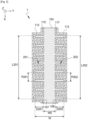
- THE figures 1 And 2 schematically represent a first embodiment of a light source 101 according to the invention. They also show an orthonormal reference frame ⁇ X; Y; Z ⁇ .
- the Figure 1 represents a sectional view in a plane ⁇ Y; Z ⁇ while the Figure 2 represents a sectional view in a plane ⁇ X; Y ⁇ .
- the light source 101 comprises a substrate 102, a resonant cavity 120.
- the substrate 102 extending parallel to a plane ⁇ X; Y ⁇ .
- the Figure 1 represents only a portion of the substrate 102.
- the latter can be massive, it can have very large dimensions compared to the other elements of the source 101.
- the substrate 102 is for example made of silicon.
- the resonant cavity 120 is, for example, a laser source cavity or an electroluminescent source cavity.
- the cavity 120 is advantageously configured to produce an emission of a light beam in a wavelength range between 0.8 ⁇ m and 20 ⁇ m, including the near infrared and a portion of the mid-infrared.
- the cavity 120 is said to be “frontal emission”. That is to say that the emission is produced by a lateral surface of the cavity 120, oriented in this case in a first direction X also called “propagation direction”.
- the cavity 120 has a ridge shape, called a “ridge” in English, stretching along the propagation direction X.
- it has a high aspect ratio with a length, measured along X, of between 20 ⁇ m and 1000 ⁇ m, or even between 100 ⁇ m and 5000 ⁇ m, and a width, measured along a second direction Y, parallel to the propagation direction X, of between 5 ⁇ m and 100 ⁇ m, and preferably between 5 ⁇ m and 20 ⁇ m.
- the cavity 120 may have a height, measured along a third direction Z, of between 2 ⁇ m and 20 ⁇ m, and preferably between 2 ⁇ m and 10 ⁇ m.
- the cavity 120 implements a distributed feedback to allow the establishment of resonant modes.
- it comprises two lateral diffraction gratings 201, 202 (discussed below) to achieve the distributed feedback on the electromagnetic field.
- the cavity 120 comprises a stack 103 of layers, each layer extending parallel to the substrate 102.
- the stack 103 comprises for example an active layer 104, which is also called an “active region” or “amplifying region”.
- the active layer 104 is configured to emit the electromagnetic field.
- the stack 103 also comprises a first confinement layer 105, called the “lower confinement layer” or “lower cladding layer”, extending between the active region 104 and the substrate 102.
- the active layer 104 rests on the inner confinement layer 105.
- the stack 103 also comprises a second confinement layer 106, called the “upper confinement layer” or “upper cladding layers”, resting on the active region 104.
- the active layer 110 separates the two confinement layers 105, 106.
- the three layers 104, 105, 106 thus form a vertical stack of layers, each layer 104, 105, 106 extending parallel to the substrate 102.
- Said stack 103 is delimited by a flank extending perpendicular to the substrate 102.
- Said flank comprises in particular two surfaces 107, 108 forming a first side 107 and a second side 108.
- the two sides 107, 108 are opposite each other.
- the first side 107 is in this case oriented along -Y and the second side 108 is oriented along +Y.
- the confinement layers 105, 106 contribute to the confinement of the electromagnetic field in the cavity 120, in particular along the Z direction, normal to the substrate 102. In this way, the electromagnetic field remains mainly localized at the level of the active layer 104 and makes it possible, for example, to promote the stimulated emission of the active layer 104.
- the confinement layers 105, 106 are, for example, configured to have optical indices n 105 , n 106 strictly lower than an average optical index n 104 of the active layer 104.
- average optical index n 104 of the active layer 104 we mean an optical index taking into account the indices of the layers or sub-layers composing the active layer 104.
- the confinement layers 105, 106 are for example made of III-V alloy such as InP.
- the active layer 104 may be configured so that the emission of the electromagnetic field is at least spontaneous and preferably spontaneous and stimulated. The latter case allows operation in laser mode of the source 101.
- the emission may be based on inter-band emission also called “interband cascade emission” in English. It may be preferentially based on inter-subband emission also called “quantum cascade emission” or “quantum cascade emission” in English.
- the active layer 104 comprises for example a stack of sub-layers made of III-V material, forming a succession of quantum wells and potential barriers. The stack of sub-layers extends for example parallel to the substrate.
- the active layer 104 comprises for example a multilayer of InGaAs / AlInAs or InAlAs / AlGaInAs.
- each guided mode in the cavity 120 can see an effective optical index n eff which may have a value different from the optical indices of the layers of the stack 103 considered independently of one another. This difference is notably due to the geometry of the different layers. This is the reason why the effective optical index n eff of the guided mode is considered.
- the effective optical index n eff can be determined numerically. An estimate of the effective optical index n eff can be determined from the average optical index in the stack 103. It is however preferable to take into account all the elements making it possible to achieve the confinement of the electric field in the cavity 120, such as the geometry (thickness and/or width) of the stack 103 and/or the presence of reflective layers.
- the substrate 102 has an optical index n 102 .
- n eff > n 102 the guided mode of the cavity 120 is not likely to couple with the substrate 102.
- the substrate 102 participates in the confinement of the guided modes in the cavity 120.
- n eff ⁇ n 102 the guided mode in the cavity 120 is likely to couple with the substrate 102, inducing optical losses and reducing the efficiency of the source 101.
- the source 101 comprises the insertion of a first metal layer 111, called the "lower metal layer", between the substrate 102 and the stack of layers 103.
- the lower metal layer 111 extends parallel to the substrate 102 and the first confinement layer 105 extends against this lower metal layer 111.
- the lower metal layer 111 can extend away from the substrate 102 or extend against the latter.
- the interaction of the guided modes in the cavity 120 with the surface of the lower metal layer 111 maintains the guided modes in the cavity 120. In this way, the transmission of the guided modes to the substrate 102 is inhibited and the efficiency of the source 1 is preserved, even if the substrate 102 exhibits a strong optical index allowing it to couple with the guided modes in the cavity 120.
- the lower metal layer 111 extends against the substrate 102.
- the stack 103 rests, by its first confinement layer 105, against the lower metal layer 111.
- the lower metal layer 111 extends over the substrate 102, under the stack 103 and beyond the stack 103.
- the lower metal layer may be made of gold, silver or titanium. It has a thickness, measured perpendicular to the substrate 102, of between greater than or equal to ⁇ /10 where ⁇ is the wavelength of the guided world considered. Considering a wavelength range ⁇ between 0.8 ⁇ m and 20 ⁇ m, the thickness of the lower metal layer 111 is for example between 80 nm and 2 ⁇ m.
- the cavity 120 also comprises a first insulating layer 115 and a second insulating layer 117 extending against, respectively, the first and second sides 107, 108 of the stack 103.
- the insulating layers preferably have optical indices lower than the effective optical index in the cavity. Thus, these layers provide confinement by index contrast.
- These insulating layers 115, 117 are, for example, made of silicon nitride SiN.
- the cavity 120 also comprises a second metal layer 112 and a third metal layer 113.
- the second and third metal layers 112, 113 extend perpendicular to the substrate 102 and parallel to the first and second sides 107, 108 of the stack 103, respectively.
- the second metal layer 112 extends against the first insulating layer 115, covering the first side 107.
- the third metal layer 113 extends against the second insulating layer 117, covering the second side 108.
- the second and third layers 112, 113 make it possible to laterally confine the guided modes or improve the lateral confinement offered by the index contrast of the insulating layers 145, 117.
- the first and second insulating layers 115, 117 make it possible to electrically insulate the stack 103 from the second and third metal layers 112, 113. Indeed, the injection of charge carriers, making it possible to stimulate the emission of an electromagnetic field, is preferentially carried out in a direction perpendicular to the substrate. Thus, the insulating layers 115, 117 make it possible to avoid a short circuit of the active layer 104 and in particular of the various sub-layers which may compose this active layer 104.
- the second and third metal layers 112, 113 are electrically connected to the lower metal layer 111 with which they are in direct contact. This connection makes it possible to fix the electrical potential of the second and third metal layers 112, 113.
- the stack 103 comprises two faces 109, 110, opposite one another: a first face 109, called the “lower face”; and a second face 110, called the “upper face”.
- the lower face 109 of the stack corresponds to the face of the first confinement layer 105 in contact with the lower metal layer 111.
- the cavity 120 comprises a fourth metal layer 118 also called “additional metal layer” or “upper metal layer” extending against the upper face 110 of the stack 103.
- the stack 103 is sandwiched between two metal layers 111, 118 which can act as electrodes. These electrodes make it possible to apply an electric field to the stack 103 making it possible to assist the generation of photons in the cavity 120 and more specifically not the active region 104.
- said metal layers 111, 118 are electrically insulated from each other.
- the lateral metal layers 112, 113 are electrically connected to the lower metal layer 111.
- the upper metal layer 118 is therefore insulated from the lateral metal layers 112, 113.
- the first and second insulating layers 115, 117 extend vertically, beyond the stack 103 to cover edges of the fourth metal layer 118.
- the side metal layers 112, 113 could be electrically connected to the top metal layer 118 and insulated from the bottom metal layer 111.
- the side metal layers 112, 113 could be connected to a different metal layer 111, 118.
- the side metal layers 112, 113 could be insulated from the top and bottom metal layers 111, 118.
- the second, third and fourth metal layers 112, 113, 118 may be made from gold, silver or titanium or from different metal materials.
- the confinement layers 105, 106 can be doped, promoting the conduction of the electric current through the active layer 104.
- Cavity 120 of the figures 1 And 2 implements a distributed feedback of the resonant modes, called “DFB” for "distributed feedback” in English.
- the resonant guided modes are established in response to the action of a diffraction grating extending over one face of said cavity.
- the stack 103 has lateral corrugations at its first and second sides 107, 108. The shape and period of these corrugations as well as the index contrast (between the stack and the insulating layers 115, 117 in this case) form first and second diffraction gratings 201, 202, called “lateral diffraction gratings”. In this way, the modes guided in the cavity 120 can interact with these lateral diffraction gratings.
- the lateral diffraction gratings 201, 202 are formed by periodic trenches, extending perpendicular to the substrate 102 (therefore in the Z direction), dug in the stack 103 in the Y direction. These trenches form a periodic corrugation at the sides of the stack 103.
- the trenches are distributed in the propagation direction X. They are arranged, for the first and second lateral gratings 201, 202, according to, respectively, first and second constant pitches P201, P202, measured in the propagation direction X. In this way, each guided mode is established parallel to the substrate 102 and mainly in the length of the cavity 120, in other words in the propagation direction X in the figures 1 And 2 .
- the lateral corrugations of the Figure 2 have, in top view, straight shapes, similar to teeth dug into the stack 103.
- the shape of the corrugations may be different as long as it has periodic patterns. It may be undulations or triangles. However, from the point of view of manufacturing these corrugations, it may be easier to engrave straight teeth into the sides of the stack 103.
- the insulating layers 115, 117 extend against the sides 107, 108 of the stack 103 and in particular in a conformal manner against lateral corrugations.
- the metal layers lateral corrugations 112, 113 extend conformally against the insulating layers 115, 117. Since the diffraction gratings 201, 202 are partly formed by the index contrast with the stack 103, the insulating layers can be deposited differently. For example, in one variant, the insulating layers 115, 117 can be deposited non-conformally against the lateral corrugations so as to erase the corrugations. In this case the metal layers 112, 113 then extend against the insulating layers 115, 117 in a planar manner.
- the first and second steps P201, P202 of the two lateral networks 201, 202 are preferably equal, for example to within 10%, or even 5%. Thus, they constructively reinforce the counter-reaction exerted on the modes in the cavity 120.
- the stack 103 may also comprise a third diffraction grating on its upper face 110. It may have, in the same way as the first and second lateral gratings 201, 202, a periodic corrugation formed of trenches distributed along the propagation direction X, with a third constant pitch, preferably equal to the first pitch P201 of the first lateral grating 201.
- the trenches of the third grating extend along a different direction, for example along the Y direction (they may be obtained by partial etching of the stack 103 along the -Z direction).
- the stack 103 may also include an additional diffraction grating at its lower face 109, on the same principle as explained above.
- the cavity 120 comprises only the lateral diffraction gratings 201, 202. Indeed, the latter make it possible to obtain a counter-reaction distributed over the guided modes, while maintaining a restricted vertical size. Indeed, it is not necessary to have a thick layer on (or under) the stack 103 to carry out an etching making it possible to obtain a diffraction grating.
- the formation of a lateral grating is simple to implement. It can be carried out by anisotropic etching of the sides 107, 108 of the stack 103. It is also easy to form lateral gratings having different pitches (and therefore different orders) within the same stack 103 or for different stacks 103 of the same set of stacks 103 (for example manufactured in the same step).
- the lateral networks 201, 202 as schematically illustrated in the Figure 2 , have a length L201, L202, measured in the Z direction, equal to 20% of the length of the stack 103.
- the networks 201, 202 are produced by etching slots in the stack 103.
- the stack 103 has a width W, measured perpendicular to the propagation direction Z, varying between two extreme widths W0 and W1. The difference between these two extreme widths corresponds to the depth D201, D202 of the corrugations (in this case the trenches), measured along the direction Y.
- a coupling force ⁇ 201 , ⁇ 202 can be defined for each lateral grating 201, 202. This coupling force is proportional to the interaction of each guided mode in the stack 103 with the diffraction gratings 201, 202. Each guided mode interacts with a total coupling force ⁇ corresponding to the sum of the coupling forces of the cavity 120.
- the coupling strengths ⁇ 201 , ⁇ 202 of the lateral gratings are proportional to the contrasts ⁇ n 201 , ⁇ n 202 of the effective indices seen by the guided modes for each lateral grating 201, 202.
- the contrasts ⁇ n 201 , ⁇ n 202 are a function of the difference in effective indices seen by the guided modes in etched areas of the grating (i.e., the indices of the insulating layers 115, 117) and in unetched areas of the grating. They also depend on the depth D201, D202 and the duty cycles of the trenches forming the diffraction gratings 201, 202. For example, up to a certain limit, the deeper the slits, the greater the contrasts ⁇ n 201 , ⁇ n 202 .
- the lateral gratings 201, 202 have preferably equal pitches P201, P202, in order to achieve a distributed feedback on the same guided modes. However, it is not obligatory for the depths D201, D202 or the lengths L201, L202 of the gratings 201, 202 to be equal.
- the lengths of the lateral gratings 201, 202 are, however, advantageously equal to the length, measured along the propagation direction X, of the cavity 120. In this way, it is not necessary to form deep slots, thus limiting the attenuation of the modes by the gratings 201, 202.
- the lower confinement layer 105 may have a different shape, notably comprising a portion, called a “pedestal”, extending laterally beyond the active region 104.
- the lower confinement layer 105 comprises, for example, first and second sub-layers, each extending parallel to the substrate 102 and one on top of the other.
- the first sub-layer is in contact with the active region 104. It extends, for example, in the vertical extension (i.e. perpendicular to the substrate 102) of the active region 104. It may be delimited by a flank, common to the flank delimiting the active region 104.
- the second sub-layer forms the pedestal. It extends against the lower metal layer 111.
- the first sub-layer extends against the second sub-layer.
- the second sub-layer extends under the active region 104 and extends laterally beyond the active region 104.
- the second sub-layer extends for example against the entire lower metal layer 111.
- the first side 107 of the stack 103 extends only over a certain height (measured perpendicular to the substrate 102) of the stack 103. In particular, it extends over the entire height of the active region 104 and the entire height of the upper confinement layer 106.
- the first side 107 extends only against a portion only of the height of the lower confinement layer 105, in particular over the entire height of the first sub-layer of the lower confinement layer 105.
- the second side 108 of the stack 103 only extends over the height of the active region 104, the height of the upper confinement layer 106 and the height of the first sub-layer of the lower confinement layer 105.
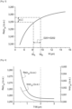
- FIG. 3 shows a result of a modal analysis carried out by finite elements allowing to adjust the depths D201, D202 of the diffraction gratings 201, 202 to obtain a predefined total coupling force ⁇ .
- the Figure 3 shows more particularly the result of a parametric study of the effective index n eff seen by a guided mode TM00 (polarization perpendicular to the substrate 102) in a stack 103 according to the invention but without corrugation on these sides (i.e. with flat sides), and as a function of the width W of the stack 103 (constant over the entire length of the stack, without pedestal).
- TM00 polarization perpendicular to the substrate 102
- the modal analysis is carried out by considering a complex effective index n eff , i.e. comprising a real part and an imaginary part.
- n eff a complex effective index
- the imaginary part accounts for the optical losses of the guided mode in the cavity 120.
- FIG. 3 shows the evolution of the real part of the effective index Re( n eff ) seen by the guided mode as the width W of the stack 103 increases.
- This evolution makes it possible to determine, for two distinct widths W A and W B , an associated index contrast ⁇ n eff ( W B - W A ). Since the coupling strength with the lateral gratings 201, 202 depends on the index contrast ⁇ n eff , it is possible, thanks to this parametric study, to determine the depths D201, D202 (for example equal to ( W B - W A )/2) of the first and second lateral gratings 201, 202.
- the widths W A and W B correspond to the extreme widths W0 and W1 of the stack 103 of the Figure 2 .
- Each lateral network 201, 202 can thus have, for the desired coupling strength ⁇ , a depth D201, D202 of 0.75 ⁇ m.
- THE figures 4 And 5 show results of two parametric studies of the real parts Re( n eff ) and imaginary parts Im( n eff ) of the effective index seen by the guided mode in an optical cavity 120 according to the invention.
- the parametric studies are carried out as a function of, respectively, the thickness T106 of the upper confinement layer 106 ( Figure 4 ) and the thickness T105 of the lower confinement layer 105 ( Figure 5 ).
- the imaginary part Im( n eff ) accounts for the optical losses of the guided mode in the cavity 120. It corresponds in particular to the coupling of the guided mode with the upper metal layer 118 (for the Figure 4 ) and the lower 111 metal layer (for the Figure 5 ). The higher the imaginary part Im( n eff ), the greater the optical losses.
- Optical losses decrease monotonically with the thicknesses T105, T106. It is therefore necessary to increase the thickness T105, T106 of the confinement layers 105, 106 to reduce optical losses. At low thicknesses T105, T106, the decrease in losses can be rapid. However, there is a thickness from which losses do not decrease more rapidly than an asymptotic regime. When this regime is reached, the reduction in optical losses is at the expense of a significant thickening of the confinement layers. It is therefore advisable to identify the thickness T105, T106 from which the asymptotic regime is reached. Thus, the selection of a thickness T105, T106 allowing an asymptotic reduction in losses to be obtained presents a good compromise between reduced thickness and acceptable losses.
- FIG. 6 schematically shows a step in the manufacture of a light source 1 according to the invention.
- the manufacture is carried out from two substrates 601, 604.
- the first substrate 601 will form the substrate 102 on which the stack 103 of the light source 1 extends. It is for example made of silicon.
- the first substrate 601 has a first face 602.
- the second substrate 604 will form the first confinement layer 105 of the stack 103. It is for example made of InP. It comprises a second face 605.
- the first and second substrates 601, 604 have first and second optical indices n 601 , n 604 such that n 601 > n 604.
- the first substrate 601 is likely to induce optical losses by transmission of the guided modes.
- the manufacturing of the source 1 comprises a step of metallizing the first and second faces 602, 605 of the first and second substrates 601, 604, forming first and second metallic sub-layers 603, 606.
- the transfer of the metallized faces 602, 605 against each other is carried out so as to bond the second substrate 604 to the first substrate 601.
- the two metal sub-layers 603, 606 form a first and single metal layer 111 extending between the two substrates 601, 604.
- This first metal layer 111 is intended to form the lower metal layer 111 of the source 1, separating the stack 103 from the silicon substrate 102.
- the fabrication of the source 1 may comprise a subsequent step of forming a layer stack from the two bonded substrates 601, 604.
- the formation comprises for example an etching of the second substrate 604 so as to form the lower confinement layer 105 of the stack 103, extending against the lower metal layer 111.
- the etching is for example carried out through a hard mask, with a stop on the lower metal layer 111.
- the active region 104 and the upper confinement layer 106 can be deposited on the lower confinement layer 105.
- layers intended to form the active region 104 and the upper confinement layer 106 are deposited on the second substrate 604.
- the delimitation of the lower confinement layer 105 in the second substrate 604 delimits at the same time the active region 104 and the upper confinement layer 106.
- This delimitation (of the lower and upper confinement layers 105, 106 and of the active region 104) is preferably carried out so that the final stack 103 comprises at least one corrugation on one of its sides 107, 108.
- This corrugation makes it possible to form the diffraction grating 201 making it possible to apply a counter-reaction on a resonant mode.
- the corrugation is for example obtained through an etching mask having a crenellated edge.
- the method advantageously comprises the conformal deposition of the insulating layers 115, 117 on the sides of the stack 103 and in particular against the or lateral corrugations.
- the method also advantageously comprises conformal deposition of the lateral metal layers 112, 113 against the insulating layers 115, 117.
- the optical indices of the layers forming the stack 103 may be chosen so that at least one stationary mode of an electromagnetic field in the stack has an effective optical index n eff .
- the resulting stack extends over a first metal layer 111, the latter making it possible to limit the propagation of the guided modes towards the first substrate 601, even if the latter has a higher optical index than the effective optical index n eff seen by the guided modes.
- the thicknesses T105, T106 of the first and second confinement layers 105, 106 are preferably determined so that the optical losses associated with at least one of the guided modes of the stack 103 decrease according to an asymptotic regime.
- the steps of forming the first and second confinement layers 105, 106 are then carried out so that these layers 105, 106 have the determined thicknesses.
- These thicknesses T105, T106 are preferably calculated by means of parametric analyses as illustrated by the figures 4 And 5 .
Landscapes
- Physics & Mathematics (AREA)
- Condensed Matter Physics & Semiconductors (AREA)
- General Physics & Mathematics (AREA)
- Electromagnetism (AREA)
- Optics & Photonics (AREA)
- Geometry (AREA)
- Semiconductor Lasers (AREA)
- Optical Integrated Circuits (AREA)
Applications Claiming Priority (1)
| Application Number | Priority Date | Filing Date | Title |
|---|---|---|---|
| FR2314205A FR3157021A1 (fr) | 2023-12-14 | 2023-12-14 | Source lumineuse comprenant une cavité résonante à contreréaction répartie et procédé de fabrication d’une telle source lumineuse |
Publications (1)
| Publication Number | Publication Date |
|---|---|
| EP4572040A1 true EP4572040A1 (de) | 2025-06-18 |
Family
ID=90810030
Family Applications (1)
| Application Number | Title | Priority Date | Filing Date |
|---|---|---|---|
| EP24218706.0A Pending EP4572040A1 (de) | 2023-12-14 | 2024-12-10 | Lichtquelle mit einem resonanzhohlraum mit verteilter rückkopplung und verfahren zur herstellung einer solchen lichtquelle |
Country Status (3)
| Country | Link |
|---|---|
| US (1) | US20250202197A1 (de) |
| EP (1) | EP4572040A1 (de) |
| FR (1) | FR3157021A1 (de) |
Citations (5)
| Publication number | Priority date | Publication date | Assignee | Title |
|---|---|---|---|---|
| US7548566B2 (en) * | 2003-09-12 | 2009-06-16 | Massachusetts Institute Of Technology | Terahertz lasers and amplifiers based on resonant optical phonon scattering to achieve population inversion |
| US20110101250A1 (en) * | 2009-11-03 | 2011-05-05 | Qing Hu | Frequency tunable wire lasers |
| US20210336412A1 (en) * | 2017-05-15 | 2021-10-28 | Nippon Telegraph And Telephone Corporation | Semiconductor Optical Device |
| US20220045482A1 (en) * | 2018-12-28 | 2022-02-10 | Advanced Micro Foundry Pte. Ltd. | Improvements in or relating to a distributed feedback laser device for photonics integrated cirtuit and a method of manufacture |
| US20220344476A1 (en) * | 2014-12-23 | 2022-10-27 | Kyocera Sld Laser, Inc. | Manufacturable gallium and nitrogen containing single frequency laser diode |
-
2023
- 2023-12-14 FR FR2314205A patent/FR3157021A1/fr active Pending
-
2024
- 2024-12-10 EP EP24218706.0A patent/EP4572040A1/de active Pending
- 2024-12-12 US US18/978,980 patent/US20250202197A1/en active Pending
Patent Citations (5)
| Publication number | Priority date | Publication date | Assignee | Title |
|---|---|---|---|---|
| US7548566B2 (en) * | 2003-09-12 | 2009-06-16 | Massachusetts Institute Of Technology | Terahertz lasers and amplifiers based on resonant optical phonon scattering to achieve population inversion |
| US20110101250A1 (en) * | 2009-11-03 | 2011-05-05 | Qing Hu | Frequency tunable wire lasers |
| US20220344476A1 (en) * | 2014-12-23 | 2022-10-27 | Kyocera Sld Laser, Inc. | Manufacturable gallium and nitrogen containing single frequency laser diode |
| US20210336412A1 (en) * | 2017-05-15 | 2021-10-28 | Nippon Telegraph And Telephone Corporation | Semiconductor Optical Device |
| US20220045482A1 (en) * | 2018-12-28 | 2022-02-10 | Advanced Micro Foundry Pte. Ltd. | Improvements in or relating to a distributed feedback laser device for photonics integrated cirtuit and a method of manufacture |
Non-Patent Citations (3)
| Title |
|---|
| APIRATIKUL PAVEEN ET AL: "GaInAsSb-AlGaAsSb laterally coupled distributed-feedback metamorphic laser grown on a GaAs substrate at 2", CLEO: 2013, THE OPTICAL SOCIETY, 9 June 2013 (2013-06-09), pages 1 - 2, XP032602372, DOI: 10.1364/CLEO_SI.2013.CM2K.4 * |
| CHEN TING ET AL: "FUNDAMENTAL AREAS OF PHENOMENOLOGY (INCLUDING APPLICATIONS); Electrically Pumped Room-Temperature Pulsed InGaAsP-Si Hybrid Lasers Based on Metal Bonding", CHINESE PHYSICS LETTERS, INSTITUTE OF PHYSICS PUBLISHING, BRISTOL, GB, vol. 26, no. 6, 2009, pages 64211, XP020159039, ISSN: 0256-307X * |
| COUTARD, J.G.BRUN, M.FOURNIER, M. ET AL.: "Volume Fabrication of Quantum Cascade Lasers on 200 mm-CMOS pilot line", SCI REP, vol. 10, 2020, pages 6185 |
Also Published As
| Publication number | Publication date |
|---|---|
| FR3157021A1 (fr) | 2025-06-20 |
| US20250202197A1 (en) | 2025-06-19 |
Similar Documents
| Publication | Publication Date | Title |
|---|---|---|
| EP3540878B1 (de) | Photonenvorrichtung, die einen laser umfasst, der optisch mit einem silizium-wellenleiter verbunden ist, und herstellungsverfahren einer solchen photonenvorrichtung | |
| EP2641304B1 (de) | Heterogener hochleistungslaser und verfahren zur herstellung des lasers | |
| CA2396951C (fr) | Dispositif de photodetection a microresonateur metal-semiconducteur vertical et procede de fabrication de ce dispositif | |
| EP3182081B1 (de) | Detektionsvorrichtung mit hängenden bolometrischen membranen mit starker absorptionsleistung und starkem signal-rausch-verhältnis | |
| EP3168946A1 (de) | Laservorrichtung und herstellungsverfahren einer solchen laservorrichtung | |
| EP3432368A1 (de) | Leuchtdiode, die einen stapel mit verdünntem teil umfasst, und deren herstellungsverfahren | |
| FR2690286A1 (fr) | Cavité laser à hétérostructure semi-conductrice dissymétrique et laser équipé de cette cavité. | |
| EP3266079B1 (de) | Germanium-auf-silicium-laser in cmos-technologie | |
| EP4009456B1 (de) | Verfahren zur herstellung eines verteilten bragg-spiegels | |
| EP2432033B1 (de) | Bispektraler Mehrschichtdetektor mit Fotodioden | |
| EP0817337B1 (de) | Herstellungsverfahren für einen Oberflächenemittierenden Laser | |
| EP4572040A1 (de) | Lichtquelle mit einem resonanzhohlraum mit verteilter rückkopplung und verfahren zur herstellung einer solchen lichtquelle | |
| WO2000035060A1 (fr) | Laser de type semi-conducteur | |
| FR3100082A1 (fr) | Modulateur de phase | |
| EP3703138B1 (de) | Struktur zur erkennung einer elektromagnetischen strahlung mit hoher absorptionseffizienz, und herstellungsverfahren einer solchen struktur | |
| EP4387014B1 (de) | System mit einer lichtquelle auf einem substrat mit hohem optischen index und verfahren dafür | |
| EP0914699B1 (de) | Laservorrichtung mit einem zwischen zwei Bragg Spiegeln angebrachten Stapel epitaktischer Diodenlaser | |
| WO2004107392A2 (fr) | Structure amorphe de couplage optique pour detecteur d'ondes electromagnetiques et detecteur associe | |
| EP4016763B1 (de) | Laser mit einem verteilten bragg-spiegel und sein herstellungsverfahren | |
| EP0651477B1 (de) | Integrierte oberflächenemittierende Laservorrichtung | |
| EP4016762B1 (de) | Laser mit einem verteilten bragg-spiegel und sein herstellungsverfahren | |
| EP4576457A1 (de) | Optoelektronisches bauelement mit vergrabenem band in einer halbisolierenden struktur | |
| EP4185093B1 (de) | Verfahren zur herstellung einer quantenvorrichtung | |
| FR3074372A1 (fr) | Structure a gain, dispositif photonique comprenant une telle structure et procede de fabrication d'une telle structure a gain | |
| FR3142618A1 (fr) | Dispositif à émission de surface, système optique et procédé associé |
Legal Events
| Date | Code | Title | Description |
|---|---|---|---|
| PUAI | Public reference made under article 153(3) epc to a published international application that has entered the european phase |
Free format text: ORIGINAL CODE: 0009012 |
|
| STAA | Information on the status of an ep patent application or granted ep patent |
Free format text: STATUS: REQUEST FOR EXAMINATION WAS MADE |
|
| 17P | Request for examination filed |
Effective date: 20241210 |
|
| AK | Designated contracting states |
Kind code of ref document: A1 Designated state(s): AL AT BE BG CH CY CZ DE DK EE ES FI FR GB GR HR HU IE IS IT LI LT LU LV MC ME MK MT NL NO PL PT RO RS SE SI SK SM TR |