EP4572060A1 - Procédé de commande d'un réseau d'alimentation électrique et système d'alimentation électrique - Google Patents
Procédé de commande d'un réseau d'alimentation électrique et système d'alimentation électrique Download PDFInfo
- Publication number
- EP4572060A1 EP4572060A1 EP24215941.6A EP24215941A EP4572060A1 EP 4572060 A1 EP4572060 A1 EP 4572060A1 EP 24215941 A EP24215941 A EP 24215941A EP 4572060 A1 EP4572060 A1 EP 4572060A1
- Authority
- EP
- European Patent Office
- Prior art keywords
- network
- control unit
- segment
- decentralized
- elements
- Prior art date
- Legal status (The legal status is an assumption and is not a legal conclusion. Google has not performed a legal analysis and makes no representation as to the accuracy of the status listed.)
- Pending
Links
Images


Classifications
-
- H—ELECTRICITY
- H02—GENERATION; CONVERSION OR DISTRIBUTION OF ELECTRIC POWER
- H02J—ELECTRIC POWER NETWORKS; CIRCUIT ARRANGEMENTS OR SYSTEMS FOR SUPPLYING OR DISTRIBUTING ELECTRIC POWER; SYSTEMS FOR STORING ELECTRIC ENERGY
- H02J3/00—Circuit arrangements for AC mains or AC distribution networks
- H02J3/001—Arrangements for handling faults or abnormalities, e.g. emergencies or contingencies
-
- H—ELECTRICITY
- H02—GENERATION; CONVERSION OR DISTRIBUTION OF ELECTRIC POWER
- H02J—ELECTRIC POWER NETWORKS; CIRCUIT ARRANGEMENTS OR SYSTEMS FOR SUPPLYING OR DISTRIBUTING ELECTRIC POWER; SYSTEMS FOR STORING ELECTRIC ENERGY
- H02J3/00—Circuit arrangements for AC mains or AC distribution networks
- H02J3/12—Arrangements for adjusting voltage in AC networks by changing a characteristic of the network load
- H02J3/14—Arrangements for adjusting voltage in AC networks by changing a characteristic of the network load by switching loads on to, or off from, the networks, e.g. progressively balanced loading
-
- H—ELECTRICITY
- H02—GENERATION; CONVERSION OR DISTRIBUTION OF ELECTRIC POWER
- H02J—ELECTRIC POWER NETWORKS; CIRCUIT ARRANGEMENTS OR SYSTEMS FOR SUPPLYING OR DISTRIBUTING ELECTRIC POWER; SYSTEMS FOR STORING ELECTRIC ENERGY
- H02J13/00—Circuit arrangements for providing remote monitoring or remote control of equipment in a power distribution network
- H02J13/14—Circuit arrangements for providing remote monitoring or remote control of equipment in a power distribution network the power network being locally controlled, e.g. home energy management systems [HEMS]
-
- H—ELECTRICITY
- H02—GENERATION; CONVERSION OR DISTRIBUTION OF ELECTRIC POWER
- H02J—ELECTRIC POWER NETWORKS; CIRCUIT ARRANGEMENTS OR SYSTEMS FOR SUPPLYING OR DISTRIBUTING ELECTRIC POWER; SYSTEMS FOR STORING ELECTRIC ENERGY
- H02J2103/00—Details of circuit arrangements for mains or AC distribution networks
- H02J2103/30—Simulating, planning, modelling, reliability check or computer assisted design [CAD] of electric power networks
- H02J2103/35—Grid-level management of power transmission or distribution systems, e.g. load flow analysis or active network management
Definitions
- the invention relates to a method for controlling a power supply network and a power supply system operating according to this method.
- restoration without SCADA and EMS requires experienced engineers to manually control the restoration processes.
- manual operation may result in a suboptimal restoration process or equipment damage.
- it may lead to delayed reconnection of power systems for critical resources such as hospitals, military facilities, and transportation systems. Due to these disadvantages, both regulators and grid operators are interested in methods that can assist in the restoration of grids during a black start without SCADA.
- [2] proposes the creation of a simulation framework for this purpose.
- This framework creates and maintains an online network topology of the local network by continuously performing various classes of local measurements and collecting sensor data and mapping them to system models. These measurements are not provided via the central SCADA system, but rather by decentralized measurement devices via secondary channels, thus avoiding invalid system models that could be caused by cyberattacks on the central SCADA or EMS through false data injection. Network reconstruction is therefore based on the simulated network topology, which completely replaces the SCADA data framework.
- the disadvantage of this solution is that the simulation framework itself can be subject to cyberattacks. Furthermore, the effort required to create and maintain the simulation framework is considerable. Furthermore, automated grid restoration is not possible because the simulation framework does not fully replace SCADA and options for automated access to the power grid and its elements are largely lacking.
- the simulation framework facilitates grid restoration for technical experts, but does not yet provide the desired automation for grid restoration.
- a power control system comprising a plurality of voltage regulators, each configured to deliver regulated power to a load; a serial data communication line operatively connecting the plurality of voltage regulators; and a digital power manager connected to the serial data communication line, the digital power manager including a control unit executing stored instructions to program operating parameters of the plurality of voltage regulators over the serial data communication line and to receive monitoring data from the plurality of voltage regulators over the serial data communication line.
- the present invention is therefore based on the object of providing an improved method for controlling a power supply network and an improved power supply system operating according to this method.
- the method according to the invention is intended to allow for a rapid, flexible and effective automatic response to system events that deviate from the normal operation of the power supply system and that, for example, can or have led to exceptional system loads or to a complete or partial power failure.
- the measures according to the invention are intended to make it possible to improve the robustness and reliability of the power supply network.
- the method according to the invention is intended to significantly relieve the burden on personnel in the event of a malfunction.
- the procedure should make it possible to optimally satisfy the requirements of the users of the electricity supply network.
- the method according to the invention should be able to be implemented with simple measures and means so that the improved power supply system can be implemented with relatively low expenditure.
- Network elements of the power supply network should be controllable or connectable to or disconnectable from the power supply network as required, so that all control tasks can be optimally fulfilled after or during faults, depending on the circumstances.
- the decentralized control units record and store network-independent and/or network-dependent element properties and network-dependent element properties and priorities for the network elements, and that the network elements are switched off in stages from the network segment by the decentralized control units after the occurrence of the network failure and/or are switched on in stages to the network segment during the network reconstruction process, depending on the determined element properties and priorities.
- the power supply system comprises the central control unit and at least two network segments which operate according to the method according to the invention.
- the decentralized control units are capable of separating and reconnecting the decentralized grid units from neighboring grid units after a system event occurs, and of connecting the grid elements in stages. Once the voltage has been restored at the first grid level, the voltage at the second grid level can also be successfully restored. High-priority loads can be connected to the power grid at an early stage.
- the central control unit and the decentralized control units record network-independent and/or network-dependent element properties for the network elements, and the decentralized control units store them.
- the decentralized control units then deactivate or add the network elements to the network segment in stages, depending on the determined element properties and priorities.
- the element properties and/or priorities of the network elements of a network segment are preferably transferred periodically to the control unit of that network segment, stored there, and used for decentralized control of the network element, particularly after a system event occurs.
- Determined system data available, for example, as a framework or model, should be able to be processed automatically to solve tasks according to their priority and, for example, accelerate secure network restoration.
- the element properties and/or the priorities of the network elements of the power supply network are mapped in a model in the central control unit and that the element properties and/or the priorities of the network elements of the network units are transferred to the control units of these network units with the complete model or in a partial model for the relevant network unit and be stored there.
- the staggering of network elements for connection and/or disconnection after a system event can now preferably be carried out automatically, taking into account the priorities and/or data of the decentralized model, using dedicated rules.
- Element properties can also include historical data or information about the network elements, such as the operating states of the network elements before a power outage occurred.
- the model used preferably also stores this historical data of the network elements, which may be relevant for controlling these network elements. If a network element was not connected before a power outage, this is preferably recorded in the model and taken into account when restarting the network units.
- the rules for determining the ranking establish rankings for the grid-dependent and grid-independent element properties, taking priorities into account.
- the rules can also assign combinations of element properties to a ranking.
- a particularly advantageous feature is that the ranking can be easily performed automatically and is always optimal based on the current state of the model used.
- the transferred model or sub-model is verified and continuously updated in the network units after receipt, and that in the event of a deviation of the newly received model or sub-model from the previously processed model or sub-model, a system event is detected and the deviation is preferably identified and taken into account in the staggering of the network elements.
- model or submodel provides the decentralized control units with all the information required for the staggered setup or dismantling of the network in the decentralized network units.
- the plan for grading the network elements is preferably created automatically, taking the existing model into account. If, for example, the rules specify that transformers connected to the power grid with high impedance are connected earlier than transformers connected to the power grid with low impedance, the corresponding network elements can be read out in the model and graduating, for example, in a list. For example, transformers assigned a low priority can be switched on independently. of their transformer impedance or grid impedance are initially omitted.
- the integrity of the centrally managed model can be verified at any time. Deviations can be identified and corrected. If the deviation is identified as a system event, the decentralized control unit can take over control of the affected network unit.
- the staggered connection of network elements is preferably carried out according to a global or network-wide schedule that assigns each network element or group of network elements an individual connection time. This ensures that a large number of transformers are not randomly connected to the power grid, which could cause high inrush currents and prevent the power grid from starting up.
- a reference time is defined or a start time is communicated, from which the network elements are switched on in a staggered manner. For example, periodically repeating intervals of, for example, 10 minutes are defined, within which individually determined switch-on times are assigned to the network units.
- transformers X1, X2 ready for switch-on are not switched on at arbitrary times, but at the assigned times within the interval that occurs after the transformers X1, X2 are made available or released for switch-on.
- the transformer X1, which is assigned, for example, the time 1 minute after the start of the interval or 1/10 of the period is released for switch-on by a first control module, for example, at minute 8 or 8/10 of the period.
- a downstream second control module delays the connection of transformer X1 until 1 minute after the start of the interval or 1/10 of the period of the next interval, i.e. until the start time assigned to transformer X1 within the preferably periodically occurring intervals.
- a grid is defined that repeats periodically and, for example, has a period duration in the range of 3 to 10 minutes. If a transformer is not switched on at a certain time within a first period, it is preferably switched on at the same time within the next period.
- the process of connecting network elements is delayed with a fixed or variable delay time. This measure prevents the occurrence of high inrush currents within a network unit due to the simultaneous connection of several transformers.
- Network-dependent element properties include, for example, the operating status, the importance, and the arrangement of the network elements within the network topology or the history of the operation of the network elements, for example the switching states of the network elements before the occurrence of a system event.
- Grid-independent element properties include, for example, the technical specifications of the respective network element.
- Properties of the network elements that arise after connection to the power supply network and are dependent on the use of the network element within the power supply network are grid-dependent properties.
- the impedances relevant for inrush currents depend significantly on the length of the connecting cables or interconnecting lines via which a network element, for example a transformer, is connected to the power supply network. A distinction is therefore made below between the impedance of a network element, for example the transformer impedance, and the grid impedance of a network element, for example a transformer after connection to the power supply network.
- the transformer impedance is defined as the ratio of the voltage drop across the transformer under full load conditions to the rated current and is derived from the resistance of the copper windings and the reactance of the magnetic field generated by the transformer.
- the grid impedance of a transformer depends on the transformer impedance and the impedance of the connecting cables or interconnecting lines.
- the network impedances of the transformers are of primary importance for the inrush currents.
- transformers with higher grid impedances and/or higher transformer impedances are connected first.
- Priority is normally given to the grid impedance, which determines the level of inrush currents.
- transformers with a high number of windings which typically have a high transformer impedance, are connected first.
- Transformers with low transformer impedances are preferably connected with a delay.
- priority is given to transformers that are supplied via a long stub line, for example, and therefore have a higher grid impedance.
- Priority connection of transformers with high grid impedance is advantageous because the grid impedance dampens the transformer's inrush current.
- Transformers that are, for example, topologically centrally connected in the power supply network and therefore have a low network impedance are therefore preferably switched on with a delay.
- priorities for the network elements are defined by the central control unit and/or the decentralized control units and stored by the decentralized control units. Subsequently, the network elements are disconnected from or connected to the network segment by the decentralized control units in a staggered manner depending on the defined priorities. If a transformer with low transformer impedance or network impedance has a high priority, its connection can also be prioritized.
- the staggered connection of network elements can also be implemented by considering a combination of grid-dependent and grid-independent element properties.
- Grid-dependent element properties are usually more important than grid-independent element properties.
- the connection of a network element that would have a later priority due to low impedance, for example can occur at an earlier point in time and be compensated for by foregoing the connection of other network elements. Therefore, the staggered connection does not necessarily have to be rigidly defined according to a single rule.
- the switching times are determined based on the determined element properties and the established priorities. For transformers with identical specifications, the one with the higher priority is therefore switched on first. Likewise, a transformer that, for example, serves a hospital or a major railway line can be switched on first, even though it has a lower transformer impedance or grid impedance than a transformer that is switched on later but has a lower priority.
- the process of connecting network elements preferably occurs with a delay depending on the state of the power supply network or dependent parameters, such as the network voltage and/or the network frequency. If, for example, the network frequency is in the lower part of the target range, the connection is preferably delayed. If the voltage and/or frequency reach the specified target ranges, the transformers may also be connected after a predetermined delay.
- the available feed-in power is also important for the staggered and delayed connection of network elements.
- the staggered and delayed connection of network elements takes into account the level of harmonic distortion occurring in the power supply network.
- the occurrence of harmonic distortion can disrupt the startup of the power supply network or cause damage to connected loads.
- the invention provides for harmonic distortion in the power supply network to be limited and a corresponding limit value to be prevented from being exceeded.
- the proportion of harmonic distortion in the power grid is measured and compared with a limit value.
- the connection of grid elements, particularly transformers is delayed until the harmonic distortions are again below the limit value.
- the connection of grid elements can also be accelerated if the harmonic distortions are below a second limit value, allowing for rapid start-up of the power grid when the harmonic distortions are low. Delay times are therefore preferably calculated taking into account the measured harmonic distortions.
- the proportion of harmonic distortions when connecting network elements, in particular transformers is determined centrally or decentrally by simulation, preferably using the model or the associated submodel, and delay times for connecting the network elements are defined in such a way that a specified limit value is not exceeded during the simulation.
- harmonic distortions in the power grid are still preferably measured and monitored.
- the transformers are connected in such a way that the first transformer winding is connected to the first grid level, and the second transformer winding is connected to the second grid level only after a fixed or variable delay. This measure limits the inrush currents.
- the transformer core is magnetized before the second transformer winding is connected to the second grid level.
- Transformers should preferably be connected or disconnected at times optimized for the occurrence of inrush currents and overvoltages. Transformers should preferably be connected in the area of a voltage maximum, and they should preferably be disconnected in the area of a current minimum. The switching points should preferably be calculated individually for each transformer, taking remanence fluxes into account.
- Grid segments can also include power sources such as generators, converters, and transformers. If a grid segment includes network elements in the form of generators, these are disconnected from the grid segment after a system event is detected by the decentralized control unit and preferably transferred to a standby state if at least some of the grid status data lies outside a specified target range. For example, water turbines continue to operate so that the generator outputs a voltage with an amplitude and frequency that lies within the target range required for connecting the generators. These measures enable grid restoration within a very short time, possibly within a few minutes.
- the decentralized control unit After detecting a system event that results in the shutdown of power sources, such as generators, converters, and transformers, the decentralized control unit reconnects them to the first grid level of the associated grid segment if at least some of the grid status data lies within a specified target range.
- generators are connected if the amplitude, frequency, and phase position of the generated voltage largely coincide with the amplitude, frequency, and phase position of the voltage of the first grid level to which the generators are connected. According to the invention, this synchronization process is controlled accordingly.
- the decentralized control unit has a communication channel to local load control units, for example, to control units in locomotives, through which loads can be connected to the second network level or further network levels. After a system event occurs, the decentralized control unit can disconnect the loads from or connect them to the associated network segment depending on network status data and/or defined priorities.
- the decentralized control units can therefore switch all essential network elements, such as power sources, generators, converters, inverters, batteries, transformers or loads, as required in order to ensure the most optimal operation of the power supply network and, in the event of a power failure, a rapid and automated network restoration.
- the network elements which are controlled and/or regulated and/or switched according to the invention are permanently connected to at least one of several network levels, the number of which is determined by the network operator, or can be connected by switching elements.
- all network segments potentially present in a power supply network such as power sources, generators, converters, inverters, batteries, transformers, loads, or capacitors, can be controlled or connected to or disconnected from the power supply network.
- network elements that are important for orderly grid restoration can be controlled or disconnected.
- the network elements can not only be connected to or disconnected from the power grid, but their behavior and/or properties can also be controlled.
- a transformer can be connected to or disconnected from the power grid. Individual transformer windings can also be switched as needed.
- Power supply devices can also be switched and controlled.
- a generator unit which includes a turbine coupled to the generator, can be controlled such that its speed corresponds to the frequency of the power grid before the generator switches are actuated.
- the invention thus relates to a dynamic hybrid control system for a power supply network, which uses central and decentralized control resources situationally and intervenes in the power supply network in a decentralized, automatic and efficient manner when a defined system event has occurred.
- System events typically occur when the central control unit, for example a central control system SCADA (Supervisory Control and Data Acquisition System), is no longer operational, is no longer accessible, is malfunctioning, possibly suffering from overload and/or a cyber attack.
- SCADA Supervisory Control and Data Acquisition System
- tasks of the central control unit should be flexibly taken over by the decentralised control segments in order to ensure the continued operation of the power supply network or to intervene correctively, for example to prevent a partial and possibly progressive or complete power failure or to carry out a rapid and controlled grid restoration after a partial or complete power failure.
- the centralized and decentralized arrangement of the control intelligence makes it possible to detect faults that could lead to a partial or complete power outage and initiate the necessary measures in a decentralized manner.
- the power systems according to the invention are therefore robust and resilient to the effects of disturbances.
- the central control unit possibly the SCADA, is relieved and can still perform tasks if possible or be checked and restarted in the event of a cyber attack.
- System events can occur and be detected in different ways.
- the communication link between the central control unit and the decentralized control unit or the decentralized control units are monitored, and a failure of this communication link is detected as the first system event.
- the decentralized control unit assumes that if there is a disruption in communication between the central and decentralized control units, there is or could be a disruption in the transmission of control signals from the central control unit to the associated network segment, which is why the decentralized control unit takes over control of the associated network segment.
- a monitoring module is provided in at least one of the decentralized control segments, which monitoring module permanently checks the connection between the central control unit and the decentralized control unit by comparing data or signals that are transmitted from the decentralized control segment to the central control unit and mirrored from the central control unit back to the decentralized control segment in order to detect a first system event in the event of a deviation that preferably exceeds a threshold value.
- the occurrence of a release command issued by the central control unit and any associated parameters is monitored, and the occurrence of the release command is detected as a second system event. If the central control unit detects, for example, a malfunction, overload, or cyberattack, a release command can be issued to the decentralized control segments or the decentralized control units to free up resources for the central control unit.
- the central control unit can decentralize control of individual or multiple, or possibly all, network segments as needed.
- the release command is valid for a predetermined period of time or a period of time specified with the release command or until revoked by the central control unit.
- the integrity of the data transmitted by the central control unit is checked by comparing it with locally acquired or stored data, and a lack of integrity is detected as a fourth system event. This measure prevents a cyberattack from spreading unhindered throughout the entire power system.
- the decentralized Control units take control of the network segments until the integrity of the central control unit is restored.
- grid parameters such as grid voltage and/or grid frequency are monitored in the decentralized control segments, and deviations from a specified voltage or frequency range are detected as a fourth system event.
- the central control unit is operational but may not have detected a problem that has arisen in the power grid, which is why the decentralized control unit takes over control and can intervene correctively. Since communication exists between the central control unit and the decentralized control units in this case, the takeover of control is preferably accompanied by communication between the central control unit and the decentralized control units. For example, a request is sent to the central control unit, which subsequently issues a release command.
- the decentralized control unit can therefore shut down or disconnect grid segments after a system event, for example, if the grid voltage or frequency falls below their setpoints. This prevents a so-called brownout or partial grid failure from progressing and leading to a total outage.
- the decentralized control unit can reconnect network elements in the associated network segment if the network status data are within the specified target ranges.
- network elements By analyzing historical status data, it is determined whether network elements were connected to the network segment prior to the system event or whether they were switched off by the central control unit. If network elements were switched off prior to the system event, they can be omitted. However, rules can be defined according to which the decentralized control unit switches previously switched off network elements back on to the corresponding network segment. For example, if a power source or generator was switched off and the grid frequency is in the lower part of the target range, a rule can be set up to switch on the relevant power source to stabilize the grid.
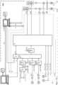
- Fig. 1 shows an example of a power supply system SVS with a power supply network VN, which is controlled in central operation by a central control unit 1, for example, a SCADA (Supervisory Control and Data Acquisition System) using a central control program that has control modules.
- the power supply network VN is divided into several network segments VNsx, VNsy, VNsg, which are traversed by the network levels N1, N2, two of which are shown as examples.
- Each of the network segments VNsx, VNsy, VNsg is assigned a decentralized control segment CSx, CSy, CSg, which comprises a decentralized control unit 20 and at least one control module 2A, 2B.
- the decentralized control unit communicates with the control modules 2A, 2B via data lines c1, c2.
- each of the network units NEx, NEy, NEg is assigned a software module of the central control program.
- the network units NEx, NEy, NEg can be configured identically or differently and are shown only as examples.
- a first network unit NEy contains two network elements, for example transformers X1, X2, with associated switching elements, disconnectors T such as circuit breakers S1, S2, and a second network unit NEy contains three network elements, for example transformers X1, X2, X3 with associated switching elements S1, S2.
- the network segments VNsx, VNsy, VNsg show elementary electrical circuits with transformers X1, X2, X3, which are connected or connectable to the first network level N1 via circuit breaker S1 and disconnector T, and to the second network level N2 via second circuit breaker S2. Furthermore, loads L are connected or connectable to the second network level N2 via load switch S3. Preferably, all switches S1, S2, and S3 are controllable by the decentralized control units 20.
- the network segment VNsg top right in Fig. 1 symbolically shown comprises two generators G1, G2, which can be connected to the first network level N1 via disconnector T and circuit breaker Y1; Y2.
- all switches S1, S2, S3; Y1, Y2 can be controlled by the decentralized control units 20.
- a third network unit NEg which comprises a decentralized control segment CSg and a network segment VNsg with two network elements in the form of generators G1, G2, which can be connected to the first network level N1 by means of isolating switches T and switching elements Y1, Y2.
- the network units NEy and NEg are shown schematically. Any number of additional network units NE can be provided.
- the network elements X1, X2, X, G1, G2 or the switching elements S1, S2, S3, Y1, Y2 connected thereto can be controlled by the decentralized control units 20 by means of the control modules 2A, 2B.
- the correct execution of the control of network elements X1, X2, X, G1, G2 and switching elements S1, S2, S3, Y1, Y2 is preferably checked. If a switching operation has not been correctly executed or acknowledged, substitute actions are preferably taken.
- equivalent network elements are connected to the network segment.
- transformer X1, which was previously not connected is connected to the first network level N1 instead of transformer X2, which is displaying a fault, or generator G1, which was previously not connected, is connected to the first network level N1 instead of generator G2, which is displaying a fault.
- an error message can be issued, which is forwarded to the operating or maintenance personnel of the power system.
- circuit breakers S1, S2 If the status of circuit breakers S1, S2 is unclear, and a transformer X1 could not be disconnected from the network N1, N2, further switching operations are performed to isolate this transformer X1 and safely disconnect it from the network N1, N2. If necessary, adjacent conductors are interrupted. Therefore, alternative switching devices or equivalent switching operations are preferably defined and stored for each network element to ensure an alternative shutdown of the relevant network element.
- Fig. 1 Alternative switching elements Sa1, Sa2 are provided at network levels N1 and N2. These are activated if the primary switching devices, i.e., circuit breakers S1 and S2, exhibit an undefined state and can no longer be activated. The alternative switching elements Sa1, Sa2 are provided in such a way that the relevant network element can be safely removed from network N1, N2 and the function of other network elements is not impaired as far as possible.
- the central control unit 1 is connected, on the one hand, to a central database 10D and, on the other hand, via a data bus nb and several branches nbx, nby, nbg to the decentralized control units 20 of the decentralized control segments CSx, CSy, CSg, which in turn are connected to a decentralized database 20D.
- a dash-dotted double arrow symbolizes that parts of the data stored in the central database and relating to the network unit NEx are preferably transferred to the decentralized database 20D of the network unit NEx.
- the data of the power supply network VN are therefore preferably stored centrally in the central control unit 1 and decentrally in a mosaic manner in the decentralized control units 20.
- the information of the power supply network VN preferably the network topology, the quantity structure, network-dependent and network-independent information on the network elements and the Switching elements, control information and organizational information are therefore preferably available redundantly, so that the centrally stored information is stored in a decentralized mosaic.
- Fig. 1 shows, by way of example, that the network segments VNsx, VNsy, VNsg are stored as models or submodels MVNsxz, MVNsyz in the central database 10D, preferably as part of an overall model MVN.
- the central model MVNsxz of the network segment VNsx was transmitted via a data line or data channel lm to the decentralized database 20D and is managed, monitored, and, if necessary, processed as a decentralized model MVNsxd.
- an online network topology of the local network is preferably created and maintained by continuously performing various classes of local measurements and collecting sensor data and mapping them to the system model.
- the models are updated in parallel in the central control unit 1 and the decentralized control unit 20.
- highly simplified models can also be used.
- the decentralized control unit 20 preferably periodically checks the data transmitted from the central control unit 1 with the locally determined and stored data in order to detect inadmissible deviations and thus a third system event.
- Fig. 1 shows that the central model sxz of the network segment VNsx and the decentralized model MVNsxd, which is managed by the decentralized control unit 20, differ from each other.
- the decentralized control unit 20 in this example determined that switches S1 and S2 are closed and entered this accordingly into the decentralized model MVNsxd.
- the central model MVNsxz currently transmitted by the central control unit 1 reports that switches S1 and S2 are open, which is why the central model MVNsxz is not adopted and a third system event is detected.
- a list of staggered network elements is created, each of which is assigned a ranking order in which they are connected to or disconnected from the power supply network VN.
- a list is created based on first rules R1, with which the network elements are connected to the power supply network VN.
- a list is created based on second rules R2, with which the network elements are disconnected from the power supply network VN.
- the lists with staggered network elements can be created particularly easily by linking the rules R, R1, R2 with the decentralized model MVNsxd.
- the network elements are connected within a time frame, preferably at specified times within a periodically repeating interval. For example, intervals of 10 minutes are defined, within which specific connection times are assigned to the network units. For each of the network elements or for groups of network elements, times within the interval or a corresponding time frame can be specified.
- transformers X2 which, for example, have a high transformer impedance or grid impedance and a high priority, are connected first.
- Transformers X3, which, for example, have a high transformer impedance or grid impedance but a lower priority, are connected second.
- Transformers X5, which have a low transformer impedance or grid impedance, are connected third.
- Transformers X1, which have a high transformer impedance or grid impedance but no relevant priority, are connected fourth.
- the ranking can also be entered directly into the model.
- the staggering of the network units using the specified rules and thus also the network reconstruction after a power failure can be carried out particularly easily.
- the central control unit 1 and the decentralized control units 20 are connected by further unidirectional or Bidirectional transmission channels 111, 112 are interconnected, which may be integrated into the data bus nb or implemented as separate lines.
- the transmission lines or data transmission channels are preferably provided redundantly, ensuring high availability of the data transmission system.
- a radio network and a wired network are provided, which operate, for example, according to Internet protocols.
- the decentralized control unit 20 can also receive feedback from the control modules 2A, 2B, which, for example, relate to measurements of the state of the assigned network segment VNsx, for example physical data of the first and/or second network level N1, N2 or state data of the assigned network elements X1, X2, X, G1, G2 and switching elements S1, S2, S3, Y1, Y2.
- the control modules 2A, 2B relate to measurements of the state of the assigned network segment VNsx, for example physical data of the first and/or second network level N1, N2 or state data of the assigned network elements X1, X2, X, G1, G2 and switching elements S1, S2, S3, Y1, Y2.
- the control segments CSx, CSy, CSg with the decentralized control units 20, which have decentralized control programs, are designed such that they can partially or completely control the associated network segments VNsx, VNsy, VNsg.
- the control and management of the network units NEx, NEy, NEg is assumed by the decentralized control units 20 according to the invention.
- the power supply system SVS can therefore operate in a centralized mode in which the control of the network units NEx, NEy, NEg is carried out by the central control unit 1, and in a decentralized mode in which the control of the network units NEx, NEy, NEg is carried out by the decentralized control units 20.
- Normal operation refers to the central operation of the power supply system SVS, in which no disturbances, such as malfunctions or communication errors, or interventions by the system itself or the operator at the control level or the grid level occur.
- a partial or complete change between centralized operation and decentralized operation can also be initiated optionally by the network operator
- the central control unit 1 can also transfer parts of the power supply system SVS to decentralized operation.
- monitoring signals are exchanged between the central control unit 1 and the decentralized control unit 20 via a line or a bidirectional data channel 111.
- Signals emitted by the decentralized control unit 20 and reflected back by the central control unit 1 are checked for consistency in the decentralized control unit 20. In the event of a deviation that exceeds a specified range or threshold, a malfunction, a communication error, or a failure of the central control unit is detected, thus triggering a first system event.
- a release command with an attribute can be transmitted from the central control unit 1 to the decentralized control unit 20 via a line 112 or via a unidirectional or bidirectional data channel, the detection of which represents a second system event, namely the active transfer of control of the network unit NEx from the central Control unit 1 to the decentralized control unit 20.
- the duration of the validity of the release command can be determined by the transmitted attribute.
- Fig. 1 further shows that the voltage U N1 and the frequency f N1 of the first network level N1 are measured by the control modules 2A, 2B and compared with limit values U min , U max ; f min , f max .
- the control module 2A reports to the control unit 20 that the voltage U N1 is below the permissible minimum value U min .
- the second control module 2B reports that the frequency f N1 is below the permissible minimum value f min . Since there may not be a fault message from the central control unit 1, the decentralized control unit 20 assumes that the central control unit 1 has lost control, which is why a fourth system event is detected.
- system events mentioned above can also occur cumulatively. Furthermore, other system events, such as the effects of fire, explosions, or water, can be taken into account.
- the respective decentralized control unit 20 takes control of the assigned network segment VNsx.
- the deviation of the voltage U N1 of the first network level N1 from the limit value U min can also cause a total network failure, after which a decentralized network reconstruction takes place under the control of the decentralized control units 20.
- Fig. 2 shows the inventive power supply system SVS from Fig. 1 with a preferably configured network unit NEx, which is suitable for detecting and handling various system events and which allows hybrid operation of the power supply system SVS, in which the central control unit 1 and the decentralized control unit 20 can alternately assume tasks for controlling the assigned network segment VNsx depending on requirements and the situation.
- the description of the power supply system SVS is given as an example for the network unit NEx in this preferred embodiment.
- the function of the central control unit 1 and thus the occurrence of the first system events are monitored via line 111, which is connected to a process module 21.
- Release commands are transmitted via line 112 from the central control unit 1 to a process module 22, which forwards the release command or maintains it for a specific or programmable time. This time period is dynamically set by a set command s22. The transmission of a release command is therefore detected at the output of the process module 22 as the occurrence of a second system event.
- Signals representing the occurrence of first, second, third, and fourth system events can be transmitted from the decentralized control unit 20 to the process module 21 via line 12.
- a first system event is signaled, for example, if data communication via the nbx bus line fails.
- a second system event is signaled if the enable command was transmitted via the nbx bus line.
- a third system event is signaled if the comparison of data from the central control unit 1 and the decentralized control unit 20, for example, the comparison of the central model MVNsxz and the decentralized model MVNsyd described above, has a negative result.
- a fourth system event is signaled if, for example, the process module 231 has reported with the nd signal that the voltage U or the frequency f of the first and/or second network level N1, N2 is outside the target range and, if applicable, a network failure has occurred.
- the process modules 21, 22 apply a logical 1 to the input of the subsequent AND gate 241 or 242, thereby activating the control module 2A.
- the process module 23 then checks whether the conditions are met to implement the decentralized control and, in this preferred embodiment, to actuate the switching elements S1 and S2 via the switching modules 26, 28 in the assigned network segment VNsx.
- shutdown commands are sent from the decentralized control unit 20 via signal lines co, cu directly to the switching modules 26, 28.
- the circuit breaker S2 is opened and the transformer X1 is disconnected from the second grid level N2.
- the first circuit breaker S1 is opened and the transformer X1 is disconnected from the first grid level N1.
- Process module 231 to which measuring lines 131, 132 are fed, checks whether the voltage U N1 and its frequency f N1 of the first network level N1 are within the specified target range. If this is the case, this is reported from the output of process module 231 to the next process module 2311, which forwards the status message with a fixed or variable delay, which can be specified by a set signal s2311. The delay ensures that the voltage U N1 has stabilized at the first network level N1.
- the process module 231 is preferably programmable using the setting command s231.
- the target ranges for the grid voltage and the grid frequency are preferably adjustable so that, for example, grid elements with high impedance are connected earlier and grid elements with low impedance are connected only when grid restoration is practically complete and the grid has returned to normal.
- the signal nd also reports the network status to the decentralized control unit 20, which, depending on existing rules, issues shutdown signals via the lines cu, co, for example, if the voltage U N1 and its frequency f N1 are outside the target ranges.
- the operating state S of the system is checked via line 133, which can be transferred by the service personnel from automatic operation to service operation, in which the personnel, but not the decentralized control unit 20, can carry out switching operations.
- Line I34 is used to check whether the disconnector T is closed so that the transformer x1 can be connected to the first network level N1.
- circuit breaker S1 The historical switching state of circuit breaker S1 is checked via line 135. As soon as circuit breaker S1 is opened, a timer begins running in process module 232, which can preferably be set to a specific value using a signal s232. The output of process module 232 therefore indicates whether transformer X1 was connected until shortly before a system event at grid level N1 occurred. If this is not the case, the control logic refrains from reconnecting transformer X1, which had previously been normally disconnected.
- the switch-on process can be started if a stable network is reported at the output of the process module 2311, line 133 does not indicate service operation, line 134 shows the closed state of the disconnector T and it is signaled at the output of the process module 232 that the network element or the transformer X was connected to the network levels N1, N2 until the occurrence of the system event and must therefore be connected again to the network levels N1, N2 when the network is restored.
- a start signal is transmitted to process modules 241 and 242 via line 123 and, if necessary, delayed by process modules 2341, 2342.
- the start signal is preferably delayed by the process modules 2341, 2342 to ensure that sufficient power generators or generators G1, G2 are connected to the first grid level N1 and that the connection of the grid element(s) or transformer X1 does not overload the grid.
- the delay of the process modules 2341, 2342 is preferably fixed or optionally programmable via setting commands or signal lines s2341, s2432. For example, if all generators are connected to the grid, the delay can be set to 0.
- the notification of a system event on the output line 121, 122 of the process module 21 and/or 22 causes an activation signal or a switching command to be transmitted from at least one of the two process modules 241, 242 via the line 141 and/or 142 to the process module 25, which transmits the switching command via output line 125, the process module 251 and its output line 1251 to the switching module 26, which actuates the first circuit breaker S1 with the control signal I25, which connects the transformer X1 to the first network level N1 via the closed disconnector T.
- the process module 251 was programmed using the setting command s251 such that the switching command is forwarded with a specified delay or at a specific time selected such that the network elements or transformers X are connected to the first network level N1 in a staggered manner.
- the staggered connection preferably takes into account the properties of the network elements and/or their priority.
- each transformer can be assigned a specific delay starting at a specific, variable or fixed point in time.
- a start time can be a start signal to initiate grid restoration. If grid restoration occurs within a periodic cycle of, say, 600 seconds, each grid element can be individually assigned a unique start time.
- Transformers X1 and X2, for example, are started at 111 seconds and 130 seconds, respectively.
- Various sequences with fixed or variable delays and start times can be implemented; it is essential that the connection is staggered and the stressful inrush currents are reduced to a minimum wherever possible.
- the output signal 1251 which leads to the actuation of the first circuit breaker S1, is fed to the second switching module 28 with a further delay via the process module 252, which is programmable using the set command s252.
- the process module 252 ensures that the connection of the transformer X1 to the second network level N2 by actuating the second circuit breaker S2 only occurs after the transformer X1 has been connected to the first network level N1 and any inrush currents have already subsided.
- the switching state of the first circuit breaker S1 is reported via line 135 to the process module 27, which only forwards the switching signal from the process module 252 to the second switching module 28 via output line 127 when the actuation of the first circuit breaker S1 has been confirmed via line 135.
- a reset signal r is preferably transmitted back from the process module 27 to the process module 252 in order to restart the delay process and thereby prevent the second circuit breaker S2 from being actuated without the required delay after the actuation of the first circuit breaker S1.
- stationary or mobile loads L for example electric locomotives, are shown, which, controlled by a local control unit 30, are connected via a load switch S3 to the second network level N2, for example a catenary level.
- the decentralized control unit 20 communicates with the local control unit 30 via a data bus or control bus in order to after the occurrence of a system event, preferably taking into account the network status, to control the loads L via the local control unit 30 and to remove them from the network if necessary.
- Fig. 3 shows the SVS power supply system from Fig. 2 in a simplified embodiment.
- the release command is transmitted from the central control unit 1 via the decentralized control unit 20 and the line or data bus 12 to the process module 21.
- Line 112 and the process modules 22, 2342, and 242 are omitted in this case.
- the switching signal at the output of the process module 241 is preferably transmitted directly to the input of the process module 251.
- Fig. 4 shows the SVS power supply system from Fig. 3 with the central control unit 1 and with a network unit NEg, which comprises a network segment VNsg with two generators G1, G2 and a control segment CSg with a decentralized control unit 20 and two control modules 2A, 2B, by means of which the generators G1, G2 and/or circuit breakers Y1, Y2 can be controlled depending on the occurrence of system events.
- a network unit NEg which comprises a network segment VNsg with two generators G1, G2 and a control segment CSg with a decentralized control unit 20 and two control modules 2A, 2B, by means of which the generators G1, G2 and/or circuit breakers Y1, Y2 can be controlled depending on the occurrence of system events.
- the communication between the central control unit 1 and the decentralized control unit 20 takes place via the data bus nbg to determine preferably all system events, as described with reference to Fig. 1 , Fig. 2 or Fig. 3 System events are reported to the process module 21 via lines 12, 111.
- the process module 23 in turn checks whether all conditions for taking over control are met and, if necessary, transmits a start signal or activation signal to a control module 29 with a delay via a process module 2341, which is preferably programmable.
- Process module 231 which is connected to measuring lines 131, 132, checks whether the voltage U N1 and its frequency f N1 of the first network level N1 are within the specified target range. If so, this is reported from the output of process module 231 to the next process module 2311, which forwards the status message with a fixed or variable delay, which can be specified by a set signal s2311. The delay ensures that the voltage U N1 has stabilized at the first network level N1.
- Target ranges are preferably selected accordingly so that the generators G1, G2 can help to guide the voltage U N1 and its frequency f N1 into the target ranges required for the process sequences according to Fig. 2 and Fig. 3 are provided.
- the grid frequency f N1 is particularly critical for the switching of the grid elements G1, G2. If the grid frequency f N1 is too low, generators G1, G2 are typically connected, and if the grid frequency f N1 is too high, they are typically disconnected.
- the target ranges are preferably adjustable using a setting command s231, so that individual adaptation to the generators G1, G2 and their use in the topology of the power supply network VN is possible.
- Process modules 2321 and 2322 which receive the switching state of switching elements Y1 and Y2 via lines 1295 and 1296, check whether switching elements Y1 and Y2 were closed before the system event occurred and whether generators G1 and G2 were connected to the first grid level N1. During grid restoration, those generators G1 and G2 that were previously connected to the grid are normally connected. However, if necessary, additional generators are connected according to the existing rules.
- the generators G1, G2 can be connected to or disconnected from the first grid level N1 by the switching elements or generator switches Y1, Y2.
- the switching elements Y1, Y2 are controlled by a generator module 29 via control lines 1293 and 1294.
- the generator module 29 can also directly access the generators G1, G2 or connected elements, such as a turbine controller TR, via additional control lines 1291 and 1292, for example, to adjust the speed of the generators G1, G2.
- current operating data of the generators G1, G2 such as the generator voltage U G1 , U G2 , the frequency f G1 , f G2 and the phase position ⁇ 1, ⁇ 2 of the generator voltage U G1 , U G2 are fed to the generator module 29 via lines l G1 , l G2 .
- mains voltage U N1 , the mains frequency f N1 and the phase position ⁇ N of the mains voltage U N1 are supplied to the generator module 29 via the line l N1 .
- generators G1, G2 are preferably disconnected from the first grid level N1 by actuating switching elements Y1, Y2 and preferably placed on standby.
- Control lines 1291 and 1292 keep generators G1 and G2 in operation so that they are ready for restart without delay.
- the speed of generators G1, G2 is maintained at a value that corresponds to the frequency f N1 of the voltage U N1 of the first grid level N1.
- the generators G1, G2 are restarted after they have been synchronized with the grid frequency f N1 and the phase position ⁇ N1 of the grid voltage U N1 .
- the generator speed is preferably increased from a value below the grid frequency f N1 to a synchronization speed that at least approximately corresponds to the grid frequency f N1 .
- the system then waits until the phase position ⁇ 1, ⁇ 2 of the generator voltage U G1 , U G2 has approached the phase position ⁇ N1 of the voltage U N1 of the first grid level N1 by a predetermined value, after which the switching elements or generator switches Y1, Y2 are actuated.
- Fig. 5 shows the SVS power supply system from Fig. 1
- two network units NEx, NEy which are independently suitable for network construction on the first network level 1 and on the second network level 2 and can be separated from one another and coupled to one another on the first network level 1 and on the second network level 2 as soon as the network construction has been completed on both sides.
- the network units NEx, NEy are identically constructed for this exemplary embodiment, but in practice often have very different network topologies with numerous network elements that can be switched on and/or off in a staggered manner.
- the first network levels N1 of the network units NEx, NEy can be separated from each other and reconnected to each other by first switching units NS1xy, NS1yx using switching signals Z1y, Z1x.
- the second network level N2 of the network units NEx, NEy can be separated from each other and reconnected to each other by second switching units NS2xy, NS2yx using switching signals Z2y, Z2x.
- the elements of the decentralized control segments CSx, CSy, as described in Fig. 2 and Fig. 3 are each combined in a control module 250.
- the elements of the decentralized control segments CSx, CSy, as described in Fig. 4 described with reference to a network unit NEg are each summarized in a control module 290.
- the network units NEx, NEy are isolated from each other by the switching units NS1xy, NS1yx; NS2xy, NS2yx at both levels N1, N2.
- the power failure was triggered, for example, by a lightning strike, which also interrupted the communication connections between the central control unit 1 and the decentralized control units 20. Thus, several system events occurred simultaneously.
- the segments of the first network level N1 can be interconnected by operating the switching units NS1xy and NS1yx.
- the segments of the second network level N2 can be interconnected by operating the switching units NS2xy and NS2yx. Connection to other network segments is performed in the same way.
- Signals I311y, I321y, I361y signal the voltage, frequency and phase position of the first network level N1 of the second network unit NEy to the control module 290 of the first network unit NEx.
- Signals I311x, I321x, I361x signal the voltage, frequency and phase position of the first network level N1 of the first network unit NEx to the control module 290 of the second network unit NEy.
- Signals I312y, I322y, I362y signal the voltage, frequency and phase position of the second network level N2 of the second network unit NEy to the control module 250 of the first network unit NEx.
- Signals I312x, I322x, I362x signal the voltage, frequency and phase position of the second network level N2 of the first network unit NEx to the control module 250 of the second network unit NEy.
- the two network units NEx, NEy are designed to synchronize the voltages of the first network level N1 generated by the generators G1, G2 with regard to amplitude and phase position and to operate the switching units NS1xy, NS1yx as soon as synchronization has been achieved within a tolerance window.
- the connection to the network units NEx, NEy on the first network level N1 is made by closing the switching units NS2xy, NS2yx, preferably monitoring whether the level and phase position of the voltages of the segments of the second network level N2 of the two network units NEx, NEy match.
- the network unit NEx or NEy that first generated the voltage on the first and/or second network level N1, N2 can already actuate the corresponding switching units NS1xy, NS2xy or NS1yx, NS2yx.
- the neighboring network unit NEx or NEy can thus detect the voltage at the output of the neighboring and connected switching unit NS1xy, NS2xy or NS1yx, NS2yx and perform synchronization.
- the network structure in the network units NEx or NEy is preferably staggered according to a plan that has been defined for the model or submodel MVNsxd, MVNsyd used.
Landscapes
- Engineering & Computer Science (AREA)
- Power Engineering (AREA)
- Remote Monitoring And Control Of Power-Distribution Networks (AREA)
Applications Claiming Priority (1)
| Application Number | Priority Date | Filing Date | Title |
|---|---|---|---|
| EP23216923.5A EP4572059A1 (fr) | 2023-12-14 | 2023-12-14 | Procédé de commande d'un réseau d'alimentation électrique et système d'alimentation électrique |
Publications (1)
| Publication Number | Publication Date |
|---|---|
| EP4572060A1 true EP4572060A1 (fr) | 2025-06-18 |
Family
ID=89223210
Family Applications (2)
| Application Number | Title | Priority Date | Filing Date |
|---|---|---|---|
| EP23216923.5A Pending EP4572059A1 (fr) | 2023-12-14 | 2023-12-14 | Procédé de commande d'un réseau d'alimentation électrique et système d'alimentation électrique |
| EP24215941.6A Pending EP4572060A1 (fr) | 2023-12-14 | 2024-11-27 | Procédé de commande d'un réseau d'alimentation électrique et système d'alimentation électrique |
Family Applications Before (1)
| Application Number | Title | Priority Date | Filing Date |
|---|---|---|---|
| EP23216923.5A Pending EP4572059A1 (fr) | 2023-12-14 | 2023-12-14 | Procédé de commande d'un réseau d'alimentation électrique et système d'alimentation électrique |
Country Status (1)
| Country | Link |
|---|---|
| EP (2) | EP4572059A1 (fr) |
Citations (5)
| Publication number | Priority date | Publication date | Assignee | Title |
|---|---|---|---|---|
| DE19600547A1 (de) * | 1995-06-27 | 1997-01-09 | Mitsubishi Electric Corp | Umrichterschutzgerät für elektrisches Netz |
| US20080074373A1 (en) | 2004-07-16 | 2008-03-27 | Alain Chapuis | Digital Power Manager For Controlling And Monitoring An Array Of Point-Of-Load Regulators |
| EP3407453A1 (fr) * | 2017-05-22 | 2018-11-28 | Siemens Aktiengesellschaft | Stabilisation d'un réseau de courant électrique |
| JP2022500998A (ja) * | 2018-11-13 | 2022-01-04 | 三菱電機株式会社 | マイクログリッドを構成するシステム、方法、及びコンピュータプログラム製品 |
| CN115332014B (zh) * | 2022-08-02 | 2023-06-20 | 中铁建电气化局集团第三工程有限公司 | 一种铁路牵引供电电路及变压器控制装置 |
-
2023
- 2023-12-14 EP EP23216923.5A patent/EP4572059A1/fr active Pending
-
2024
- 2024-11-27 EP EP24215941.6A patent/EP4572060A1/fr active Pending
Patent Citations (5)
| Publication number | Priority date | Publication date | Assignee | Title |
|---|---|---|---|---|
| DE19600547A1 (de) * | 1995-06-27 | 1997-01-09 | Mitsubishi Electric Corp | Umrichterschutzgerät für elektrisches Netz |
| US20080074373A1 (en) | 2004-07-16 | 2008-03-27 | Alain Chapuis | Digital Power Manager For Controlling And Monitoring An Array Of Point-Of-Load Regulators |
| EP3407453A1 (fr) * | 2017-05-22 | 2018-11-28 | Siemens Aktiengesellschaft | Stabilisation d'un réseau de courant électrique |
| JP2022500998A (ja) * | 2018-11-13 | 2022-01-04 | 三菱電機株式会社 | マイクログリッドを構成するシステム、方法、及びコンピュータプログラム製品 |
| CN115332014B (zh) * | 2022-08-02 | 2023-06-20 | 中铁建电气化局集团第三工程有限公司 | 一种铁路牵引供电电路及变压器控制装置 |
Non-Patent Citations (5)
| Title |
|---|
| A. PANDEY: "Electrical and Computer Engineering Department", 2019, CARNEGIE MELLON UNIVERSITY, article "SUGAR-R: Robust Online Restoration Platform for SCADA-Absent Grid" |
| A. PANDEY: "SUGAR-R: Robust Online Restoration Platform for SCADA-Absent Grid, Electrical and Computer Engineering Department", 2019, CARNEGIE MELLON UNIVERSITY |
| BOSCH JULIUS ET AL: "Ultrafast restoration after nationwide blackout: concept, principles & example of application", 2020 INTERNATIONAL CONFERENCE ON SMART ENERGY SYSTEMS AND TECHNOLOGIES (SEST), IEEE, 7 September 2020 (2020-09-07), pages 1 - 6, XP033830297, DOI: 10.1109/SEST48500.2020.9203071 * |
| J. BOSCH ET AL.: "INTERNATIONAL CONFERENCE ON SMART ENERGY SYSTEMS AND TECHNOLOGIES (SEST", vol. Ultrafast restoration after nationwide blackout: c, 9 July 2020, IEEE |
| REPORT INTO THE LOW FREQUENCY DEMAND DISCONNECTION (LFDD) FOLLOWING GENERATOR TRIPS AND FREQUENCY EXCURSION ON, 19 August 2019 (2019-08-19) |
Also Published As
| Publication number | Publication date |
|---|---|
| EP4572059A1 (fr) | 2025-06-18 |
Similar Documents
| Publication | Publication Date | Title |
|---|---|---|
| EP2608355B1 (fr) | Dispositif d'alimentation en courant sans interruption de consommateurs électriques et procédé de fonctionnement du dispositif | |
| EP2872777A2 (fr) | Procédé pour commander un générateur électrique | |
| EP2713462A1 (fr) | Installation de stockage d'énergie et communication de module | |
| EP3549226A1 (fr) | Procédé de rétablissement d'un réseau d'alimentation électrique | |
| EP4120508A1 (fr) | Procédé et agencement informatique centrale destinés à la prévision d'un état de réseau, ainsi que produit-programme informatique | |
| EP2936646B1 (fr) | Système et procédé pour séparer une alimentation électrique locale d'un réseau électrique | |
| EP2912741B1 (fr) | Onduleur, procédé faire fonctionner un onduleur et installation d'alimentation en énergie comprenant un onduleur | |
| DE102019127198A1 (de) | Verfahren zum betrieb einer energieerzeugungsanlage und energieerzeugungsanlage mit dem verfahren | |
| EP2899828B1 (fr) | Système de commande pour une installation électrique destinée au redémarrage de l'installation électrique après une panne de courant | |
| EP4572060A1 (fr) | Procédé de commande d'un réseau d'alimentation électrique et système d'alimentation électrique | |
| WO2018096028A1 (fr) | Procédé de commande d'une éolienne | |
| EP3599689A1 (fr) | Procédé de fonctionnement d'un réseau électrique | |
| DE102015006868A1 (de) | Verfahren zur Detektion und Identifikation von Betriebsmittelausfällen in einem elektrischen Netz | |
| WO2022002486A1 (fr) | Système et procédé pour optimiser un état de commutation d'un agencement de commutation d'un agencement de distribution électrique | |
| EP2993548B1 (fr) | Réglage d'une alimentation en tension | |
| EP2899829B1 (fr) | Dispositif de réglage pour une installation électrique pour la séparation sûre de l'installation électrique d'un réseau d'alimentation en énergie et procédé correspondant | |
| EP3235088B1 (fr) | Procédé et ensemble de transmission d'une énergie électrique par l'intermédiaire d'une ligne électrique | |
| EP3637572A1 (fr) | Procédé de gestion d'un réseau de transmission électrique | |
| WO2023052089A1 (fr) | Procédé de régulation de la fréquence de réseau d'un réseau d'énergie électrique et dispositif de commande correspondant | |
| EP4657699A1 (fr) | Procédé de mise en service d'un système d'alimentation électrique et système d'alimentation électrique | |
| AT524421B1 (de) | Verfahren zur zeitstaffelungsschutzkompatiblen selektiven netzkurzschlusserkennenden Überwachung des Betriebes eines elektrischen Energienetzes | |
| EP2521240A2 (fr) | Commutation électrique pour un parc éolien | |
| EP4481978A1 (fr) | Appareil et procédé de commande de sectionneur à équilibrage de tension basé sur la calibration | |
| DE102023112478A1 (de) | Verfahren zum Betrieb von elektrischen Verteilnetzen | |
| EP4415202A1 (fr) | Procédé mis en uvre par ordinateur, agencement d'analyse de réseau et produit de programme informatique |
Legal Events
| Date | Code | Title | Description |
|---|---|---|---|
| PUAI | Public reference made under article 153(3) epc to a published international application that has entered the european phase |
Free format text: ORIGINAL CODE: 0009012 |
|
| STAA | Information on the status of an ep patent application or granted ep patent |
Free format text: STATUS: THE APPLICATION HAS BEEN PUBLISHED |
|
| AK | Designated contracting states |
Kind code of ref document: A1 Designated state(s): AL AT BE BG CH CY CZ DE DK EE ES FI FR GB GR HR HU IE IS IT LI LT LU LV MC ME MK MT NL NO PL PT RO RS SE SI SK SM TR |
|
| STAA | Information on the status of an ep patent application or granted ep patent |
Free format text: STATUS: REQUEST FOR EXAMINATION WAS MADE |
|
| 17P | Request for examination filed |
Effective date: 20251218 |