EP4572162A1 - Procédé et appareil de transmission de paramètres de livre de codes, et support de stockage - Google Patents
Procédé et appareil de transmission de paramètres de livre de codes, et support de stockage Download PDFInfo
- Publication number
- EP4572162A1 EP4572162A1 EP23851608.2A EP23851608A EP4572162A1 EP 4572162 A1 EP4572162 A1 EP 4572162A1 EP 23851608 A EP23851608 A EP 23851608A EP 4572162 A1 EP4572162 A1 EP 4572162A1
- Authority
- EP
- European Patent Office
- Prior art keywords
- frequency domain
- basis vector
- codebook parameter
- spatial domain
- configuration information
- Prior art date
- Legal status (The legal status is an assumption and is not a legal conclusion. Google has not performed a legal analysis and makes no representation as to the accuracy of the status listed.)
- Pending
Links
Images

Classifications
-
- H—ELECTRICITY
- H04—ELECTRIC COMMUNICATION TECHNIQUE
- H04B—TRANSMISSION
- H04B7/00—Radio transmission systems, i.e. using radiation field
- H04B7/02—Diversity systems; Multi-antenna system, i.e. transmission or reception using multiple antennas
- H04B7/04—Diversity systems; Multi-antenna system, i.e. transmission or reception using multiple antennas using two or more spaced independent antennas
- H04B7/06—Diversity systems; Multi-antenna system, i.e. transmission or reception using multiple antennas using two or more spaced independent antennas at the transmitting station
-
- H—ELECTRICITY
- H04—ELECTRIC COMMUNICATION TECHNIQUE
- H04B—TRANSMISSION
- H04B7/00—Radio transmission systems, i.e. using radiation field
- H04B7/02—Diversity systems; Multi-antenna system, i.e. transmission or reception using multiple antennas
- H04B7/022—Site diversity; Macro-diversity
- H04B7/024—Co-operative use of antennas of several sites, e.g. in co-ordinated multipoint or co-operative multiple-input multiple-output [MIMO] systems
-
- H—ELECTRICITY
- H04—ELECTRIC COMMUNICATION TECHNIQUE
- H04B—TRANSMISSION
- H04B7/00—Radio transmission systems, i.e. using radiation field
- H04B7/02—Diversity systems; Multi-antenna system, i.e. transmission or reception using multiple antennas
- H04B7/04—Diversity systems; Multi-antenna system, i.e. transmission or reception using multiple antennas using two or more spaced independent antennas
- H04B7/0413—MIMO systems
- H04B7/0456—Selection of precoding matrices or codebooks, e.g. using matrices antenna weighting
- H04B7/0478—Special codebook structures directed to feedback optimisation
-
- H—ELECTRICITY
- H04—ELECTRIC COMMUNICATION TECHNIQUE
- H04B—TRANSMISSION
- H04B7/00—Radio transmission systems, i.e. using radiation field
- H04B7/02—Diversity systems; Multi-antenna system, i.e. transmission or reception using multiple antennas
- H04B7/04—Diversity systems; Multi-antenna system, i.e. transmission or reception using multiple antennas using two or more spaced independent antennas
- H04B7/06—Diversity systems; Multi-antenna system, i.e. transmission or reception using multiple antennas using two or more spaced independent antennas at the transmitting station
- H04B7/0613—Diversity systems; Multi-antenna system, i.e. transmission or reception using multiple antennas using two or more spaced independent antennas at the transmitting station using simultaneous transmission
- H04B7/0615—Diversity systems; Multi-antenna system, i.e. transmission or reception using multiple antennas using two or more spaced independent antennas at the transmitting station using simultaneous transmission of weighted versions of same signal
- H04B7/0619—Diversity systems; Multi-antenna system, i.e. transmission or reception using multiple antennas using two or more spaced independent antennas at the transmitting station using simultaneous transmission of weighted versions of same signal using feedback from receiving side
- H04B7/0621—Feedback content
- H04B7/0626—Channel coefficients, e.g. channel state information [CSI]
-
- H—ELECTRICITY
- H04—ELECTRIC COMMUNICATION TECHNIQUE
- H04B—TRANSMISSION
- H04B7/00—Radio transmission systems, i.e. using radiation field
- H04B7/02—Diversity systems; Multi-antenna system, i.e. transmission or reception using multiple antennas
- H04B7/04—Diversity systems; Multi-antenna system, i.e. transmission or reception using multiple antennas using two or more spaced independent antennas
- H04B7/06—Diversity systems; Multi-antenna system, i.e. transmission or reception using multiple antennas using two or more spaced independent antennas at the transmitting station
- H04B7/0613—Diversity systems; Multi-antenna system, i.e. transmission or reception using multiple antennas using two or more spaced independent antennas at the transmitting station using simultaneous transmission
- H04B7/0615—Diversity systems; Multi-antenna system, i.e. transmission or reception using multiple antennas using two or more spaced independent antennas at the transmitting station using simultaneous transmission of weighted versions of same signal
- H04B7/0619—Diversity systems; Multi-antenna system, i.e. transmission or reception using multiple antennas using two or more spaced independent antennas at the transmitting station using simultaneous transmission of weighted versions of same signal using feedback from receiving side
- H04B7/0636—Feedback format
- H04B7/0639—Using selective indices, e.g. of a codebook, e.g. pre-distortion matrix index [PMI] or for beam selection
-
- H—ELECTRICITY
- H04—ELECTRIC COMMUNICATION TECHNIQUE
- H04B—TRANSMISSION
- H04B7/00—Radio transmission systems, i.e. using radiation field
- H04B7/02—Diversity systems; Multi-antenna system, i.e. transmission or reception using multiple antennas
- H04B7/04—Diversity systems; Multi-antenna system, i.e. transmission or reception using multiple antennas using two or more spaced independent antennas
- H04B7/06—Diversity systems; Multi-antenna system, i.e. transmission or reception using multiple antennas using two or more spaced independent antennas at the transmitting station
- H04B7/0613—Diversity systems; Multi-antenna system, i.e. transmission or reception using multiple antennas using two or more spaced independent antennas at the transmitting station using simultaneous transmission
- H04B7/0615—Diversity systems; Multi-antenna system, i.e. transmission or reception using multiple antennas using two or more spaced independent antennas at the transmitting station using simultaneous transmission of weighted versions of same signal
- H04B7/0619—Diversity systems; Multi-antenna system, i.e. transmission or reception using multiple antennas using two or more spaced independent antennas at the transmitting station using simultaneous transmission of weighted versions of same signal using feedback from receiving side
- H04B7/0658—Feedback reduction
- H04B7/066—Combined feedback for a number of channels, e.g. over several subcarriers like in orthogonal frequency division multiplexing [OFDM]
Definitions
- the present application relates to the field of communications, and in particular, to methods and apparatuses for codebook parameter transmission and a storage medium.
- a new radio (NR) system supports a variety of multi transmitting receiving point (MTRP) coordinated multi-point transmission schemes.
- the coordinated multi-point transmission schemes can be divided into coherent joint transmission (CJT) schemes and non-coherent joint transmission (NCJT) schemes.
- a traditional type II codebook design and precoder matrix indicator (PMI) reporting are only applicable to single-point transmission ways or NCJT ways, and are not applicable to multi-point coherent joint transmission ways, which leads to problems such as poor system reliability.
- Embodiments of the present application provide methods and apparatuses for codebook parameter transmission, and a storage medium to solve a problem of poor system reliability in the related art.
- An embodiment of the present application provides a method for codebook parameter transmission, performed by a terminal, including:
- the initial codebook parameter configuration information is predefined or configured by a network device.
- determining the codebook parameter in the multi-point coherent joint transmission way based on the initial codebook parameter configuration information includes:
- determining the multiple spatial domain beam quantities in the multi-point coherent joint transmission way based on the single spatial domain beam quantity X includes:
- determining the i-th spatial domain beam quantity includes: determining the i-th spatial domain beam quantity based on i-th channel estimation information.
- determining the codebook parameter in the multi-point coherent joint transmission way based on the initial codebook parameter configuration information includes:
- determining the multiple frequency domain basis vector quantities in the multi-point coherent joint transmission way based on the single frequency domain basis vector quantity Y includes:
- reporting the codebook parameter in the multi-point coherent joint transmission way includes:
- determining the codebook parameter in the multi-point coherent joint transmission way based on the initial codebook parameter configuration information includes: determining multiple non-zero coefficient quantities in the multi-point coherent joint transmission way based on the indication of the non-zero coefficient quantity.
- reporting the codebook parameter in the multi-point coherent joint transmission way includes:
- the method further includes: performing differential quantization on the non-zero coefficients.
- An embodiment of the present application further provides a method for codebook parameter transmission, performed by a network device, including:
- the initial codebook parameter configuration information is predefined or configured by the network device.
- the initial codebook parameter configuration information includes one or more of the following information:
- the spatial domain beam quantity includes one or more of the following:
- the frequency domain basis vector quantity includes one or more of the following:
- parsing the codebook parameter based on the initial codebook parameter configuration information includes:
- An embodiment of the present application further provides a terminal, including a memory, a transceiver and a processor, where the memory is used to store a computer program, the transceiver is used to receive and transmit data under control of the processor, and the processor is used to read the computer program in the memory and perform the following operations:
- the initial codebook parameter configuration information is predefined or configured by a network device.
- determining the codebook parameter in the multi-point coherent joint transmission way based on the initial codebook parameter configuration information includes:
- determining the multiple spatial domain beam quantities in the multi-point coherent joint transmission way based on the single spatial domain beam quantity X includes:
- determining the i-th spatial domain beam quantity includes: determining the i-th spatial domain beam quantity based on i-th channel estimation information.
- determining the codebook parameter in the multi-point coherent joint transmission way based on the initial codebook parameter configuration information includes:
- determining the multiple frequency domain basis vector quantities in the multi-point coherent joint transmission way based on the single frequency domain basis vector quantity Y includes:
- reporting the codebook parameter in the multi-point coherent joint transmission way includes:
- determining the codebook parameter in the multi-point coherent joint transmission way based on the initial codebook parameter configuration information includes: determining multiple non-zero coefficient quantities in the multi-point coherent joint transmission way based on the indication of the non-zero coefficient quantity.
- reporting the codebook parameter in the multi-point coherent joint transmission way includes:
- the processor is further used to read the computer program in the memory and perform the following operation: performing differential quantization on the non-zero coefficients.
- An embodiment of the present application further provides a network device, including a memory, a transceiver and a processor, where the memory is used to store a computer program, the transceiver is used to receive and transmit data under control of the processor, and the processor is used to read the computer program in the memory and perform the following operations:
- the initial codebook parameter configuration information is predefined or configured by the network device.
- the initial codebook parameter configuration information includes one or more of the following information:
- the spatial domain beam quantity includes one or more of the following:
- the frequency domain basis vector quantity includes one or more of the following:
- parsing the codebook parameter based on the initial codebook parameter configuration information includes:
- An embodiment of the present application further provides an apparatus for codebook parameter transmission, including:
- the initial codebook parameter configuration information is predefined or configured by a network device.
- determining the codebook parameter in the multi-point coherent joint transmission way based on the initial codebook parameter configuration information includes:
- determining the multiple spatial domain beam quantities in the multi-point coherent joint transmission way based on the single spatial domain beam quantity X includes:
- determining the i-th spatial domain beam quantity includes: determining the i-th spatial domain beam quantity based on i-th channel estimation information.
- determining the codebook parameter in the multi-point coherent joint transmission way based on the initial codebook parameter configuration information includes:
- determining the multiple frequency domain basis vector quantities in the multi-point coherent joint transmission way based on the single frequency domain basis vector quantity Y includes:
- reporting the codebook parameter in the multi-point coherent joint transmission way includes:
- determining the codebook parameter in the multi-point coherent joint transmission way based on the initial codebook parameter configuration information includes: determining multiple non-zero coefficient quantities in the multi-point coherent joint transmission way based on the indication of the non-zero coefficient quantity.
- reporting the codebook parameter in the multi-point coherent joint transmission way includes:
- the apparatus further includes a quantizing module, where the quantizing module is used for performing differential quantization on the non-zero coefficients.
- An embodiment of the present application further provides an apparatus for codebook parameter transmission, including:
- the initial codebook parameter configuration information is predefined or configured by a network device.
- the initial codebook parameter configuration information includes one or more of the following information:
- the spatial domain beam quantity includes one or more of the following:
- the frequency domain basis vector quantity includes one or more of the following:
- parsing the codebook parameter based on the initial codebook parameter configuration information includes:
- An embodiment of the present application further provides a processor-readable storage medium storing a computer program, where the computer program is used for causing a processor to perform the methods for codebook parameter transmission described above.
- An embodiment of the present application further provides a computer-readable storage medium storing a computer program, where the computer program is used for causing a computer to perform the methods for codebook parameter transmission described above.
- An embodiment of the present application further provides a communication devicereadable storage medium storing a computer program, where the computer program is used for causing a communication device to perform the methods for codebook parameter transmission described above.
- An embodiment of the present application further provides a chip product-readable storage medium storing a computer program, where the computer program is used for causing a chip product to perform the methods for codebook parameter transmission described above.
- the terminal determines and reports the codebook parameter in the multi-point coherent joint transmission way based on the initial codebook parameter configuration information, thereby reporting a joint codebook parameter under an assumption of a coordinated multi-point transmission scheme, and improving reliability of a system.
- a type II codebook design mainly considers a two-layer codebook design, where a first-layer codebook W1 requires broadband for feeding back spatial domain beam information, and a second-layer codebook W2 requires subband for feeding back frequency domain information, including a linear merging coefficient of a spatial domain beam of each subband.
- a first-layer spatial domain beam information there are a total of 2N 1 N 2 O 1 O 2 candidate beams in the first-layer codebook, where N 1 N 2 represents a quantity of channel state information-reference signal (CSI-RS) antenna ports in a vertical or a horizontal direction, and O 1 O 2 represents a beam oversampling factor in the vertical or the horizontal direction.
- CSI-RS channel state information-reference signal
- the spatial domain beam is fed back on a physical uplink shared channel (PUSCH), and specific parameters include i 1,1 and i 1,2 .
- PUSCH physical uplink shared channel
- specific parameters include i 1,1 and i 1,2 .
- a specific feedback overhead bit width is shown in Table 1.
- a base station determines spatial domain decoding information based on the feedback overhead in Table 1.
- NR Rel-15 In new radio (NR) Rel-15, a Rel-15 TypeII codebook is defined. It supports rank1 and rank2 codebooks based on linear merging of beams within an orthogonal beam group. Since the Rel-15 codebook requires subband feedback of merging coefficients, and feedback of each subband includes both a subband phase coefficient and a subband amplitude coefficient, in case that a quantity of subbands is large, feedback overhead required for feeding back coefficients of all subbands is huge. In NR Rel-16, a low-overhead Rel-16 eType II codebook is defined, which compresses coefficients of each subband and feeds back the compressed coefficients to the base station.
- NR Rel-16 a low-overhead Rel-16 eType II codebook is defined, which compresses coefficients of each subband and feeds back the compressed coefficients to the base station.
- W ⁇ 2 represents the compressed coefficient, where p diff ( i, j ) represents a differential amplitude coefficient, q ( i, j ) represents a phase coefficient, and p ref represents a reference amplitude coefficient. If a strongest amplitude coefficient in W ⁇ 2 is located in a first polarization direction (i.e., the first L rows in W ⁇ 2 ), the reference amplitude coefficient is located in a second polarization direction, as shown in the above expression. If the strongest amplitude coefficient in W ⁇ 2 is located in the second polarization direction (i.e., the last L rows in W ⁇ 2 ), the reference amplitude coefficient is located in the first polarization direction, which is not repeated here.
- the differential amplitude coefficient, the phase coefficient and the reference amplitude coefficient all need to be fed back to the base station. Meanwhile, the terminal needs to report a location of the strongest amplitude coefficient.
- a corresponding differential amplitude coefficient of the strongest amplitude coefficient is defined as 1, and the phase coefficient of the strongest amplitude coefficient is defined as 0, which does not need to be reported.
- W f represents a compressed basis vector, which contains M basis vectors, and a length of each vector is N 3 , where N 3 is determined by a quantity of channel quality indicator (CQI) subbands configured by a system.
- CQI channel quality indicator
- the reference amplitude coefficient is quantized to four bits, whose value is 1 , 1 2 1 4 , 1 4 1 4 , 1 8 1 4 , ... , 1 2 14 1 4 , 0 .
- a traditional NR system supports a variety of multi transmitting receiving point (MTRP) coordinated multi-point transmission schemes, which can be divided into coherent joint transmission (CJT) schemes and non-coherent joint transmission (NCJT) schemes.
- CJT coherent joint transmission
- NCJT non-coherent joint transmission
- PDSCH physical downlink shared channel
- Rel-16 standardized an NCJT scheme SDM1a
- Rel-17 standardized a coordinated multi-point scheme based on system frame number (SFN) for transmission
- SFN system frame number
- Rel-18 standardized a CJT scheme with an increase of less than or equal to four transmission point MTRP.
- the base station needs to perform joint precoding transmission and data coherent transmission for multiple transmission points of multi-point coordination.
- CSI channel state information
- a terminal calculates precoding information based on each transmission point separately, and a traditional codebook design and precoder matrix indicator (PMI) reporting based on single-point transmission are still applicable to NCJT. Therefore, a traditional type II codebook design and PMI reporting are only applicable to single-point transmission way or NCJT way, and are not applicable to a multi-point joint CJT, resulting in inability to adopt multi-point joint CJT and a problem of low system reliability.
- PMI precoder matrix indicator
- embodiments of the present application mainly design a joint codebook for multiple transmission points in a CJT way, and the terminal can perform joint channel measurement and channel state reporting based on coordinated results of all transmission points, thereby improving reliability of a system.
- FIG. 1 is a first schematic flowchart of a method for codebook parameter transmission according to an embodiment of the present application.
- an embodiment of the present application provides a method for codebook parameter transmission, which may be performed by a terminal, such as a mobile phone, etc. The method includes the following steps.
- Step 101 determining initial codebook parameter configuration information.
- Step 102 determining a codebook parameter in a multi-point coherent joint transmission way based on the initial codebook parameter configuration information.
- Step 103 reporting the codebook parameter in the multi-point coherent joint transmission way.
- the initial codebook parameter configuration information is predefined.
- the initial codebook parameter configuration information is configured by a network device.
- the network device transmits the initial codebook parameter configuration information to the terminal, and the terminal receives the initial codebook parameter configuration information transmitted by the network device.
- the initial codebook parameter configuration information may include one or more of the following information:
- the spatial domain beam quantity may include one or more of the following:
- the frequency domain basis vector quantity may include one or more of the following:
- the codebook parameter may include codebook parameter information (codebook parameter itself) and/or a quantity of codebook parameters.
- the codebook parameter may include one or more of the following parameters:
- the terminal determines the following codebook parameters based on the initial codebook parameter configuration information predefined by a system or configured by the base station.
- the terminal determines the spatial domain beam quantity based on the initial codebook parameter configuration information predefined by the system or configured by the base station, and the terminal reports a multi-point joint spatial domain beam quantity and/or spatial domain beam information based on a CJT assumption.
- determining the codebook parameter in the multi-point coherent joint transmission way based on the initial codebook parameter configuration information includes: in case that the initial codebook parameter configuration information is a single spatial domain beam quantity X, determining multiple spatial domain beam quantities in the multi-point coherent joint transmission way based on the single spatial domain beam quantity X.
- the terminal can determine all the spatial domain beam information of a multi-point transmission based on the following ways, and report it to a base station side.
- determining the multiple spatial domain beam quantities in the multi-point coherent joint transmission way based on the single spatial domain beam quantity X includes: determining each spatial domain beam quantity in the multiple spatial domain beam quantities, where each spatial domain beam quantity is X.
- determining the multiple spatial domain beam quantities in the multi-point coherent joint transmission way based on the single spatial domain beam quantity X includes: determining each spatial domain beam quantity in the multiple spatial domain beam quantities, where each spatial domain beam quantity is X/I, and I is a quantity of the multiple spatial domain beam quantities.
- the terminal may add spatial domain beam allocation results of all transmission points/transmission point groups in field1 in PMI reporting.
- the terminal may add spatial domain beam allocation results of all transmission points/transmission point groups in part1 in CSI reporting.
- determining the i-th spatial domain beam quantity includes: determining the i-th spatial domain beam quantity based on i-th channel estimation information.
- the terminal dynamically selects the spatial domain beam quantity based on a channel estimation from different transmission points to the terminal while taking a reference signal receiving power (RSRP) of a transmission point being the highest as a loop, and a spatial domain beam quantity for each transmission point ranges from 0 ⁇ L i ⁇ X.
- RSRP reference signal receiving power
- the terminal determines the spatial domain configuration information of all transmission points/transmission point groups based on the multiple spatial domain beam configuration information, and reports spatial domain recommendation beams of all transmission points/transmission point groups.
- determining the codebook parameter in the multi-point coherent joint transmission way based on the initial codebook parameter configuration information includes: in case that the initial codebook parameter configuration information is a first index, determining multiple spatial domain beam quantities in the multi-point coherent joint transmission way based on the first index, where the first index is used to indicate the multiple spatial domain beam quantities.
- the terminal jointly determines the spatial domain configuration information of all transmission points/transmission point groups based on a single spatial domain beam configuration information and additional combination indication information of the spatial domain configuration information of all transmission points/transmission point groups, and reports spatial domain recommendation beams of all transmission points/transmission point groups.
- the additional combination indication information of the spatial domain configuration information of all transmission points/transmission point groups can be configured by a predefined way, higher layer signaling, or dynamic downlink control information (DCI) indication signaling.
- DCI dynamic downlink control information
- the terminal may determine multiple candidate L j allocation ways through the additional combination indication information, and recommend to report a kind of additional combination information i 1,3 of the spatial domain configuration information of all transmission points/transmission point groups based on a current measurement quantity i.
- the terminal may add additional combination information i 1,3 of the spatial domain configuration information of all transmission points/transmission point groups in field1 in the PMI reporting.
- the terminal may add an additional combination result of the spatial domain configuration information of all transmission points/transmission point groups in part1 in the CSI reporting.
- determining the codebook parameter in the multi-point coherent joint transmission way based on the initial codebook parameter configuration information includes: in case that the initial codebook parameter configuration information is a single frequency domain basis vector quantity Y, determining multiple frequency domain basis vector quantities in the multi-point coherent joint transmission way based on the single frequency domain basis vector quantity Y.
- the terminal determines the frequency domain basis vector (beam) quantity based on the initial codebook parameter configuration information predefined by the system or configured by the base station, and the terminal reports a multi-point joint frequency domain basis vector (beam) quantity and/or frequency domain basis vector (beam) information based on a CJT assumption.
- the reported frequency domain basis vector information can be reported separately for each data transmission layer, or can be reported uniformly and jointly for all data transmission layers.
- the terminal can determine all frequency domain basis vector information of multi-point transmission based on the following ways and report it to the base station side.
- the terminal determines frequency domain basis vector configuration factors of all transmission points/transmission point groups based on single frequency domain basis vector configuration information, and reports frequency domain recommendation basis vector information of all transmission points/transmission point groups.
- determining the multiple frequency domain basis vector quantities in the multi-point coherent joint transmission way based on the single frequency domain basis vector quantity Y includes: determining each frequency domain basis vector quantity in the multiple frequency domain basis vector quantities, where each frequency domain basis vector quantity is Y*N3/R, N3 is a subband size of a current precoder matrix indicator (PMI), and R is a subband factor.
- PMI current precoder matrix indicator
- determining the multiple frequency domain basis vector quantities in the multi-point coherent joint transmission way based on the single frequency domain basis vector quantity Y includes: determining each frequency domain basis vector quantity in the multiple frequency domain basis vector quantities, where each frequency domain basis vector quantity is (Y*N3)/(R*I), N3 is a subband size of a current precoder matrix indicator (PMI), R is a subband factor, and I is a quantity of the multiple frequency domain basis vector quantities.
- each frequency domain basis vector quantity is (Y*N3)/(R*I)
- N3 is a subband size of a current precoder matrix indicator (PMI)
- R is a subband factor
- I is a quantity of the multiple frequency domain basis vector quantities.
- the terminal may add frequency domain recommendation basis vector allocation results of all transmission points/transmission point groups in field1 in the PMI reporting.
- the terminal may add frequency domain recommendation basis vector quantity allocation results of all transmission points/transmission point groups in part1 in the CSI reporting.
- the terminal determines the frequency domain recommendation basis vector configuration factors of all transmission points/transmission point groups based on multiple frequency domain basis vector configuration information, and reports frequency domain recommendation basis vectors of all transmission points/transmission point groups.
- determining the codebook parameter in the multi-point coherent joint transmission way based on the initial codebook parameter configuration information includes: in case that the initial codebook parameter configuration information is a second index, determining multiple frequency domain basis vector quantities in the multi-point coherent joint transmission way based on the second index, where the second index is used to indicate the multiple frequency domain basis vector quantities.
- the terminal jointly determines the frequency domain basis vector configuration information of all transmission points/transmission point groups based on a single frequency domain basis vector configuration information and additional combination indication information of the frequency domain basis vector configuration information of all transmission points/transmission point groups, and reports the frequency domain recommendation basis vectors of all transmission points/transmission point groups.
- the additional combination indication information of the frequency domain basis vector information of all transmission points/transmission point groups can be configured by a predefined way, higher layer signaling, or dynamic DCI indication signaling.
- the terminal may determine multiple candidate M j allocation ways through the additional combination indication information, and recommend to report a kind of additional combination information i 1,3 of the frequency domain configuration information of all transmission points/transmission point groups based on a current measurement quantity i.
- the terminal may add additional combination information i 1,8 of the frequency domain basis vector information of all transmission points/transmission point groups in field1 in the PMI reporting.
- the terminal may add an additional combination result of the frequency domain configuration information of all transmission points/transmission point groups in part1 in the CSI reporting.
- reporting the codebook parameter in the multi-point coherent joint transmission way includes:
- the terminal may report joint frequency domain recommendation basis vector information based on all transmission points, where all transmission points correspond to one frequency domain basis vector.
- the terminal reports frequency domain recommendation basis vector information of each transmission point respectively, where one transmission point corresponds to one frequency domain basis vector.
- the terminal takes a transmission point group as a unit, the terminal reports the joint frequency domain recommendation basis vector information of the transmission point group respectively, and all transmission points in the group may report one joint frequency domain recommendation basis vector information.
- the terminal may also report the offset value i 1,8 of frequency domain basis vector of different transmission points/transmission point groups.
- determining the codebook parameter in the multi-point coherent joint transmission way based on the initial codebook parameter configuration information includes: determining multiple non-zero coefficient quantities in the multi-point coherent joint transmission way based on the indication of the non-zero coefficient quantity.
- the terminal may report a multi-point joint strongest coefficient index based on a CJT assumption through the following ways based on the indication of the non-zero coefficient quantity in the initial codebook parameter configuration information predefined by the system or configured by the base station, and the determined frequency domain basis vector information of all transmission points/transmission point groups.
- reporting the codebook parameter in the multi-point coherent joint transmission way includes:
- the reported frequency domain basis vector information may be reported separately for each data transmission layer, or may be reported uniformly and jointly for all data transmission layers.
- the terminal reports recommended reporting non-zero coefficients for each transmission point based on the indication of the non-zero coefficient quantity, and reports a strongest coefficient index (SCI) of each transmission point in the non-zero coefficients in each transmission point.
- SCI strongest coefficient index
- the terminal reports the recommended reporting non-zero coefficients for each transmission point group based on the indication of the non-zero coefficient quantity, and reports the SCI of each transmission point group in the non-zero coefficients of each transmission point group.
- the non-zero coefficients are jointly reported between each transmission point, and one SCI is reported.
- the terminal reports the recommended reporting non-zero coefficients for each transmission point based on the indication of the non-zero coefficient quantity, and reports the SCI of the first transmission point in the non-zero coefficients in each transmission point.
- the first transmission point is one of the multiple transmission points.
- the terminal reports the recommended reporting non-zero coefficients for each transmission point group based on the indication of the non-zero coefficient quantity, and reports the SCI of a first transmission point in a first transmission point group in the non-zero coefficients of each transmission point group.
- the first transmission point group is one of the transmission point groups among multiple transmission point groups, and the first transmission point is one of the transmission points in the first transmission point group.
- the non-zero coefficients are jointly reported between each transmission point.
- the method further includes: performing differential quantization on the non-zero coefficients.
- the terminal performs differential quantization on all non-zero coefficients through the following quantization schemes based on all the determined non-zero coefficients.
- each transmission point/transmission point group has 2*Li*Mi (where spatial domain is Li, and frequency domain is Mi) non-zero coefficients.
- differential quantization is performed on Li*Mi-1 non-zero coefficients in a polarization direction where an SCI of each layer is located, and differential quantization is then performed on Li*Mi non-zero coefficients in a first polarization direction, which is another polarization direction.
- each transmission point has 2*Li*Mi non-zero coefficients.
- differential quantization is performed on i*Li*Mi-1 non-zero coefficients in a polarization direction where an SCI of a first transmission point of each layer is located, and differential quantization is then performed on Li*Mi non-zero coefficients in a first polarization direction, which is another polarization direction.
- each transmission point has 2*Li*Mi non-zero coefficients.
- differential quantization is performed on i*Li*Mi-1 non-zero coefficients in a polarization direction where an SCI of a first transmission point in a first transmission point group of each layer is located, and differential quantization is then performed on Li*Mi non-zero coefficients in a first polarization direction, which is another polarization direction.
- the above scheme performs joint differential for all layers, that is, on 2* Li*Mi non-zero coefficients.
- the terminal determines and reports the codebook parameter in the multi-point coherent joint transmission way based on the initial codebook parameter configuration information, thereby reporting a joint codebook parameter under an assumption of a coordinated multi-point transmission scheme, and improving reliability of the system.
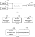
- FIG. 2 is a second schematic flowchart of a method for codebook parameter transmission according to an embodiment of the present application.
- an embodiment of the present application provides a method for codebook parameter transmission, which may be performed by a network device, such as a base station, etc. The method includes the following steps.
- Step 201 receiving a codebook parameter reported from a terminal.
- Step 202 parsing the codebook parameter based on initial codebook parameter configuration information.
- the initial codebook parameter configuration information is predefined or configured by the network device.
- the initial codebook parameter configuration information includes one or more of the following information:
- the spatial domain beam quantity includes one or more of the following:
- the frequency domain basis vector quantity includes one or more of the following:
- parsing the codebook parameter based on the initial codebook parameter configuration information includes:
- the base station indicates the initial codebook parameter configuration information to the terminal, receives the codebook parameters reported from the terminal (in the embodiment of the present application, CSI information is taken as an example for describing), and decodes the CSI information based on information reported from the terminal and/or predefined by the system.
- a base station side determines an information bit to decode the spatial domain beam information.
- the base station decodes the CSI information based on a single reporting information (TRP-common) and the information bit, and determines the spatial domain recommendation beams for all transmission points/transmission point groups.
- TRP-common reporting information
- the base station decodes the CSI information based on the single reporting information (TRP-common) and an information bit of Table 2, determines that a quantity of spatial domain recommendation beams of all transmission points/transmission point groups is the same and consistent with a configured quantity, and determines a spatial domain recommendation beam of each transmission point/transmission point group based on the quantity of spatial domain recommendation beams of all transmission points/transmission point groups.
- the base station decodes the CSI information based on the single reporting information (TRP-common) and an information bit of Table 3, determines that the quantity of spatial domain recommendation beams of all transmission points/transmission point groups is the same, where a sum of all the quantities of spatial domain recommendation beams is consistent with a configured quantity, and determines a spatial domain recommendation beam of each transmission point/transmission point group based on the quantity of spatial domain recommendation beams of all transmission points/transmission point groups.
- Table 3 i 1,1, i i 1,2, i log 2 O 1 O 2 log 2 N 1 N 2 X / i
- TRP-common single reporting information
- the terminal may add spatial domain beam allocation results of all transmission points/transmission point groups in part1 in the PMI reporting, as shown in Table 4.
- Table 4 i 1,1, i i 1,2, i i 1,3, i log 2 O 1 O 2 log 2 N 1 N 2 L i log 2 X L i
- the terminal may add spatial domain beam allocation results of all transmission points/transmission point groups in part1 in the CSI reporting, as shown in Table 5.
- Table 5 CSI part1 RI (if reported) Spatial domain beam allocation results of all transmission points/transmission point groups CQI KNZ i ⁇ log 2 X L i
- the base station decodes the CSI information based on multiple reporting information (TRP specific) and an information bit of Table 6, and determines spatial domain recommendation beam information of all transmission points/transmission point groups.
- Table 6 i 1,1, i i 1,2, i log 2 O 1 O 2 log 2 N 1 N 2 X i
- the base station jointly determines an information bit based on the single configuration information and an additional transmission point combination allocation configuration to decode CSI information, determines a quantity of spatial domain recommendation beams of all transmission points/transmission point groups, and determines a spatial domain recommendation beam of each transmission point/transmission point group based on the quantity of spatial domain recommendation beams of all transmission points/transmission point groups.
- the additional combination indication information of the spatial domain configuration information of all transmission points/transmission point groups can be configured by a predefined way, higher layer signaling, or dynamic DCI indication signaling.
- the terminal may determine multiple candidate L j allocation ways through the additional combination indication information, and recommend to report a kind of additional combination information i 1,3 of the spatial domain configuration information of all transmission points/transmission point groups based on a current measurement quantity i.
- the terminal may add additional combination information i 1,3 of the spatial domain configuration information of all transmission points/transmission point groups in field1 in the PMI reporting, as shown in Table 7.
- Table 7 i 1,1, i i 1,2, i i 1,3 log 2 O 1 O 2 log 2 N 1 N 2 L i log 2 combiantion
- the terminal may add an additional combination result of the spatial domain configuration information of all transmission points/transmission point groups in part1 in the CSI reporting, as shown in Table 8.
- Table 8 CSI part1 RI (if reported) Additional combination result of the spatial domain configuration information of all transmission points/transmission point groups CQI KNZ i ⁇ log 2 combiantion
- the base station side determines an information bit to decode the frequency domain beam information
- the base station decodes the CSI information based on the single reporting information (TRP-common) and the information bit, and determines the frequency domain recommendation basis vectors of all transmission points/transmission point groups.
- the base station decodes the CSI information based on the single reporting information (TRP-common) and the information bit, determines that a quantity of frequency domain recommendation basis vectors of all transmission points/transmission point groups is the same and consistent with a configured quantity, and determines a frequency domain recommendation basis vector of each transmission point/transmission point group based on the quantity of frequency domain recommendation basis vectors of all transmission points/transmission point groups.
- TRP-common single reporting information
- configuration or predefined information of the base station in case that the terminal reports separately for each data transmission layer, is as shown in Table 9.
- Table 9 i 1,5, i i 1,6,1, i i 1,6,2, i i 1,6,3, i i 1,6,4, i log 2 2 M log 2 N 3 ⁇ 1 M ⁇ 1 log 2 N 3 ⁇ 1 M ⁇ 1 log 2 N 3 ⁇ 1 M ⁇ 1 log 2 N 3 ⁇ 1 M ⁇ 1 M ⁇ 1 or N/A( N 3 ⁇ 19)
- the terminal can perform unified joint reporting for all data transmission layers, it is as shown in Table 10.
- Table 10 i 1,5, i log 2 2 M i 1,6, ⁇ or N/A( N 3 ⁇ 19) log 2 N 3 ⁇ 1 M ⁇ 1
- the base station decodes the CSI information based on the single reporting information (TRP-common) and the information bit, determines that a quantity of frequency domain recommendation basis vectors of all transmission points/transmission point groups is the same, where a sum of all the quantities of frequency domain recommendation basis vectors is consistent with a configured quantity, and determines a frequency domain recommendation basis vector of each transmission point/transmission point group based on the quantity of frequency domain recommendation basis vectors of all transmission points/transmission point groups.
- TRP-common single reporting information
- configuration or predefined information of the base station in case that the terminal reports separately for each data transmission layer, is as shown in Table 11.
- Table 11 i 1,5, i i 1,6,1, i i 1,6,2, i i 1,6,3, i i 1,6,4, i log 2 2 M i log 2 N 3 ⁇ 1 M i ⁇ 1 log 2 N 3 ⁇ 1 M i ⁇ 1 log 2 N 3 ⁇ 1 M i ⁇ 1 log 2 N 3 ⁇ 1 M i ⁇ 1 log 2 N 3 ⁇ 1 M i ⁇ 1 or N/A( N 3 ⁇ 19)
- the terminal can perform unified joint reporting for all data transmission layers, it is as shown in Table 12.
- Table 12 i 1,5, i i 1,6, i log 2 2 M i or N / A N 3 ⁇ 19 log 2 N 3 ⁇ 1 M i ⁇ 1
- the terminal may add frequency domain basis vector allocation results of all transmission points/transmission point groups in field1 in the PMI reporting.
- configuration or predefined information of the base station in case that the terminal reports separately for each data transmission layer, is as shown in Table 13.
- Table 13 i 1,5, i i 1,6,1, i i 1,6,2, i i 1,6,3, i i 1,6,4, i i 1,8, i log 2 2 M i or log 2 N 3 ⁇ 1 M i ⁇ 1 log 2 N 3 ⁇ 1 M i ⁇ 1 log 2 N 3 ⁇ 1 M i ⁇ 1 log 2 N 3 ⁇ 1 M i ⁇ 1 log 2 Y M i N/A( N 3 ⁇ 19)
- the terminal can perform unified joint reporting for all data transmission layers, it is as shown in Table 14.
- Table 14 i 1,5, i i 1,6, i i 1,8, i log 2 2 M i or N / A N 3 ⁇ 19 log 2 N 3 ⁇ 1 M i ⁇ 1 log 2 Y M i
- the terminal may add frequency domain basis vector allocation results of all transmission points/transmission point groups in part1 in the CSI reporting, as shown in Table 15.
- Table 15 CSI part 1 RI (if reported) Frequency domain basis vector allocation results of all transmission points/transmission point groups CQI KNZ i ⁇ log 2 Y M i
- the base station decodes the CSI information based on multiple reported information (TRP specific) and the information bit, and determines frequency domain recommendation basis vector information for all transmission points/transmission point groups.
- configuration or predefined information of the base station in case that the terminal reports separately for each data transmission layer, is as shown in Table 16.
- Table 16 i 1,5, i i 1,6,1, i i 1,6,2, i i 1,6,3, i i 1,6,4, i log 2 2 M i log 2 N 3 ⁇ 1 M i ⁇ 1 log 2 N 3 ⁇ 1 M i ⁇ 1 log 2 N 3 ⁇ 1 M i ⁇ 1 log 2 N 3 ⁇ 1 M i ⁇ 1 log 2 N 3 ⁇ 1 M i ⁇ 1 or N/A( N 3 ⁇ 19)
- the terminal can perform unified joint reporting for all data transmission layers, it is as shown in Table 17.
- Table 17 i 1,5, i i 1,6, i log 2 2 M i or N/A( N 3 ⁇ 19) log 2 N 3 ⁇ 1 M i ⁇ 1
- the base station jointly determines an information bit based on the single configuration information and an additional transmission point combination allocation configuration to decode CSI information, determines a quantity of frequency domain recommendation basis vectors of all transmission points/transmission point groups, and determines a frequency domain recommendation basis vector of each transmission point/transmission point group based on the quantity of frequency domain recommendation basis vectors of all transmission points/transmission point groups.
- the additional combination indication information of the frequency domain configuration information of all transmission points/transmission point groups can be configured by a predefined way, higher layer signaling, or dynamic DCI indication signaling.
- the terminal may determine multiple candidate L j allocation ways through the additional combination indication information, and recommend to report a kind of additional combination information i 1,3 of the frequency domain configuration information of all transmission points/transmission point groups based on a current measurement quantity i.
- the terminal may add additional combination information i 1,8 of the frequency domain configuration information of all transmission points/transmission point groups in field1 in the PMI reporting.
- configuration or predefined information of the base station in case that the terminal reports separately for each data transmission layer, is as shown in Table 18.
- Table 18 i 1,5, i i 1,6,1, i i 1,6,2, i i 1,6,3, i i 1,6,4, i i 1,8, i log 2 2 M i log 2 N 3 ⁇ 1 M i ⁇ 1 log 2 N 3 ⁇ 1 M i ⁇ 1 log 2 N 3 ⁇ 1 M i ⁇ 1 log 2 N 3 ⁇ 1 M i ⁇ 1 log 2 N 3 ⁇ 1 M i ⁇ 1 Additional combination result of the frequency domain configuration information of each transmission point/transmission point group or N/A( N 3 ⁇ 19) log 2 combination
- the terminal can perform unified joint reporting for all data transmission layers, it is as shown in Table 19.
- Table 19 i 1,5, i i 1,6, i i 1,8, i log 2 2 M i or N/A( N 3 ⁇ 19) log 2 N 3 ⁇ 1 M i ⁇ 1 Additional combination result of the frequency domain configuration information of each transmission point/transmission point group log 2 combiantion
- the terminal may add an additional combination result of the frequency domain configuration information of all transmission points/transmission point groups in part1 in the CSI reporting, as shown in Table 20.
- Table 20 CSI part1 RI (if reported) Additional combination result of the frequency domain configuration information of all transmission points/transmission point groups CQI KNZ i ⁇ log 2 combiantion
- Method 1 the quantity i of all transmission points/transmission point groups that can be reported for CSI is configured based on higher layer signaling or predefined ways.
- Method 2 the quantity i of all transmission points/transmission point groups that can be reported for CSI is implicitly determined based on a quantity of CSI resources or port groups.
- Method 3 the terminal calculates the quantity i of all transmission points/transmission point groups reported from the current CSI by itself based on a maximum quantity j of all transmission points/transmission point groups configured by the base station.
- Method 1 selection for O 1 O 2 block is consistent, and the L beams in the block are selected separately.
- Method 2 the O 1 O 2 block and the L beams in the block are selected separately.
- the network device determines and receives the codebook parameter in the multi-point coherent joint transmission way based on the initial codebook parameter configuration information, thereby reporting a joint codebook parameter under an assumption of a coordinated multi-point transmission scheme, and improving reliability of the system.
- Step 1 the terminal receives a CSI codebook configuration parameter.
- the base station can indicate the CSI codebook configuration parameter to the terminal by system predefinition or higher layer signaling.
- a higher layer signaling method can be configured by a combination of a single spatial domain beam quantity, a spatial domain beam quantity configuration factor Y, and a non-zero coefficient quantity factor.
- a higher layer signaling method can be configured separately by each of the above parameters.
- Method 1 the quantity i of all transmission points/transmission point groups that can be reported for CSI is configured based on higher layer signaling or predefined ways.
- Method 2 the quantity i of all transmission points/transmission point groups that can be reported for CSI is implicitly determined based on a quantity of CSI resources or port groups.
- Method 3 the terminal calculates the quantity i of all transmission points/transmission point groups reported from the current CSI by itself based on a maximum quantity j of all transmission points/transmission point groups configured by the base station.
- Step 4 the terminal reports i pieces of spatial domain beam information.
- the base station determines an overhead bit width of each spatial domain beam based on Table 21, and determines overhead bit widths of all transmission points/transmission point groups.
- Method 1 the O 1 O 2 block and the L beams in the block are selected separately, as shown in Table 21.
- Table 21 i 1,1, i i 1,2, i log 2 O 1 O 2 log 2 N 1 N 2 X
- Method 2 all transmission points/groups report one O 1 O 2 block, and the L beams in the block are selected separately, as shown in Table 22.
- Table 22 i 1, i i 1,2, i log 2 O 1 O 2 log 2 N 1 N 2 X
- Step 5-1 the terminal reports i pieces of frequency domain basis vector information.
- the base station determines an overhead bit width of each spatial domain beam based on Table 23, and determines overhead bit widths of all transmission points/transmission point groups.
- configuration or predefined information of the base station in case that the terminal reports separately for each data transmission layer, is as shown in Table 23.
- Table 23 i 1,5, i i 1,6,1, i i 1,6,2, i i 1,6,3, i i 1,6,4, i log 2 2 M or N/A( N 3 ⁇ 19) log 2 N 3 ⁇ 1 M ⁇ 1 log 2 N 3 ⁇ 1 M ⁇ 1 log 2 N 3 ⁇ 1 M ⁇ 1 log 2 N 3 ⁇ 1 M ⁇ 1 log 2 N 3 ⁇ 1 M ⁇ 1 M ⁇ 1 M ⁇ 1
- Table 24 i 1,5, i i 1,6, i log 2 2 M or N/A( N 3 ⁇ 19) log 2 N 3 ⁇ 1 M ⁇ 1
- Step 5-2 the terminal reports one piece of joint frequency domain basis vector information.
- the base station determines an overhead bit width of each spatial domain beam based on Table 25, and determines overhead bit widths of all transmission points/transmission point groups.
- configuration or predefined information of the base station in case that the terminal reports separately for each data transmission layer, is as shown in Table 25.
- Table 25 i 1,5 i 1,6,1 i 1,6,2 i 1,6,3 i 1,6,4 log 2 2 M or N/A( N 3 ⁇ 19) log 2 N 3 ⁇ 1 M ⁇ 1 log 2 N 3 ⁇ 1 M ⁇ 1 log 2 N 3 ⁇ 1 M ⁇ 1 log 2 N 3 ⁇ 1 M ⁇ 1 M ⁇ 1 M ⁇ 1 M ⁇ 1 M ⁇ 1
- Table 26 i 1,5 i 1,6 log 2 2 M or N/A( N 3 ⁇ 19) log 2 N 3 ⁇ 1 M ⁇ 1
- the terminal may also report the offset value i 1,8 of frequency domain basis vector of different transmission points/transmission point groups.
- Step 6 the terminal may report a multi-point joint strongest coefficient index based on a CJT assumption through the following ways based on the indication of the non-zero coefficient quantity in the initial codebook parameter configuration information predefined by the system or configured by the base station, and the determined frequency domain basis vector information of all transmission points/transmission point groups.
- the reported frequency domain basis vector information may be reported separately for each data transmission layer, or may be reported uniformly and jointly for all data transmission layers.
- Step 6-1 the terminal reports recommended reporting non-zero coefficients for each transmission point based on the indication of the non-zero coefficient quantity, and reports an SCI of each transmission point in the non-zero coefficients in each transmission point.
- Step 6-2 the terminal reports the recommended reporting non-zero coefficients for each transmission point group based on the indication of the non-zero coefficient quantity, and reports the SCI of each transmission point group in the non-zero coefficients of each transmission point group.
- the non-zero coefficients are jointly reported between each transmission point, and one SCI is reported.
- Step 6-3 the terminal reports the recommended reporting non-zero coefficients for each transmission point based on the indication of the non-zero coefficient quantity, and reports the SCI of the first transmission point in the non-zero coefficients in each transmission point.
- Step 6-4 the terminal reports the recommended reporting non-zero coefficients for each transmission point group based on the indication of the non-zero coefficient quantity, and reports the SCI of a first transmission point in a first transmission point group in the non-zero coefficients of each transmission point group. In the transmission point group, the non-zero coefficients are jointly reported between each transmission point.
- Step 7 the terminal performs differential quantization on all non-zero coefficients through the following quantization schemes based on all the determined non-zero coefficients.
- each transmission point/transmission point group has 2*Li*Mi non-zero coefficients. Firstly, in each transmission point/transmission point group, differential quantization is performed on Li*Mi-1 non-zero coefficients in a polarization direction where an SCI of each layer is located, and differential quantization is then performed on Li*Mi non-zero coefficients in a first polarization direction, which is another polarization direction.
- each transmission point For each data layer, each transmission point has 2*Li*Mi non-zero coefficients. In all transmission points, differential quantization is performed on i*Li*Mi-1 non-zero coefficients in a polarization direction where an SCI of a first transmission point of each layer is located, and differential quantization is then performed on Li*Mi non-zero coefficients in a first polarization direction, which is another polarization direction.
- each transmission point group has 2*Li*Mi non-zero coefficients.
- differential quantization is performed on i*Li*Mi-1 non-zero coefficients in a polarization direction where an SCI of a first transmission point in a first transmission point group of each layer is located, and differential quantization is then performed on Li*Mi non-zero coefficients in a first polarization direction, which is another polarization direction.
- the above scheme performs joint differential for all layers, that is, on 2* Li*Mi non-zero coefficients.
- Step 1 the terminal receives a CSI codebook configuration parameter.
- the base station can indicate the CSI codebook configuration parameter to the terminal by system predefinition or higher layer signaling.
- a higher layer signaling method can be configured by a combination of a sum of a single spatial domain beam quantity, a compression basis vector factor, and a non-zero coefficient quantity factor.
- a higher layer signaling method can be configured separately by a sum of the spatial domain beam quantity.
- Method 1 the quantity i of all transmission points/transmission point groups that can be reported for CSI is configured based on higher layer signaling or predefined ways.
- Method 2 the quantity i of all transmission points/transmission point groups that can be reported for CSI is implicitly determined based on a quantity of CSI resources or port groups.
- Method 3 the terminal calculates the quantity i of all transmission points/transmission point groups reported from the current CSI by itself based on a maximum quantity j of all transmission points/transmission point groups configured by the base station.
- Step 4 the terminal reports i pieces of spatial domain beam information.
- the base station determines an overhead bit width of each spatial domain beam based on Table 27, and determines overhead bit widths of all transmission points/transmission point groups.
- Method 1 the O 1 O 2 block and the L beams in the block are selected separately, as shown in Table 27.
- Table 27 i 1,1, i i 1,2, i log 2 O 1 O 2 log 2 N 1 N 2 X
- Method 2 all transmission points/groups report one O 1 O 2 block, and the L beams in the block are selected separately, as shown in Table 28.
- Step 5-1 the terminal reports i pieces of frequency domain basis vector information.
- the base station determines an overhead bit width of each spatial domain beam based on Table 29, and determines overhead bit widths of all transmission points/transmission point groups.
- configuration or predefined information of the base station in case that the terminal reports separately for each data transmission layer, is as shown in Table 29.
- Table 29 i 1,5, i i 1,6,1, i i 1,6,2, i i 1,6,3, i i 1,6,4, i log 2 2 M i or N/A( N 3 ⁇ 19) log 2 N 3 ⁇ 1 M i ⁇ 1 log 2 N 3 ⁇ 1 M i ⁇ 1 log 2 N 3 ⁇ 1 M i ⁇ 1 log 2 N 3 ⁇ 1 M i ⁇ 1 log 2 N 3 ⁇ 1 M i ⁇ 1 ⁇ 1
- Table 30 i 1,5, i i 1,6, i log 2 2 M i or N / A N 3 ⁇ 19 log 2 N 3 ⁇ 1 M i ⁇ 1
- Step 5-2 the terminal reports one piece of joint frequency domain basis vector information.
- the base station determines an overhead bit width of each frequency domain parameter based on Table 31, and determines overhead bit widths of all transmission points/transmission point groups.
- configuration or predefined information of the base station in case that the terminal reports separately for each data transmission layer, is as shown in Table 31.
- Table 31 i 1,5 i 1,6,1 i 1,6,2 i 1,6,3 i 1,6,4 log 2 2 M i or N/A( N 3 ⁇ 19) log 2 N 3 ⁇ 1 M i ⁇ 1 log 2 N 3 ⁇ 1 M i ⁇ 1 log 2 N 3 ⁇ 1 M i ⁇ 1 log 2 N 3 ⁇ 1 M i ⁇ 1 log 2 N 3 ⁇ 1 M i ⁇ 1 log 2 N 3 ⁇ 1 M i ⁇ 1 ⁇ 1
- Table 32 In case that the terminal can perform unified joint reporting for all data transmission layers, it is as shown in Table 32.
- Table 32 i 1,5 i 1,6 log 2 2 M i or N / A N 3 ⁇ 19 log 2 N 3 ⁇ 1 M i ⁇ 1
- the terminal may also report the offset value i 1,8 of frequency domain basis vector of different transmission points/transmission point groups.
- Step 6 the terminal may report a multi-point joint strongest coefficient index based on a CJT assumption through the following ways based on the indication of the non-zero coefficient quantity in the initial codebook parameter configuration information predefined by the system or configured by the base station, and the determined frequency domain basis vector information of all transmission points/transmission point groups.
- the reported frequency domain basis vector information may be reported separately for each data transmission layer, or may be reported uniformly and jointly for all data transmission layers.
- Step 6-1 the terminal reports recommended reporting non-zero coefficients for each transmission point based on the indication of the non-zero coefficient quantity, and reports an SCI of each transmission point in the non-zero coefficients in each transmission point.
- Step 6-2 the terminal reports the recommended reporting non-zero coefficients for each transmission point group based on the indication of the non-zero coefficient quantity, and reports the SCI of each transmission point group in the non-zero coefficients of each transmission point group.
- the non-zero coefficients are jointly reported between each transmission point, and one SCI is reported.
- Step 6-3 the terminal reports the recommended reporting non-zero coefficients for each transmission point based on the indication of the non-zero coefficient quantity, and reports the SCI of the first transmission point in the non-zero coefficients in each transmission point.
- Step 6-4 the terminal reports the recommended reporting non-zero coefficients for each transmission point group based on the indication of the non-zero coefficient quantity, and reports the SCI of a first transmission point in a first transmission point group in the non-zero coefficients of each transmission point group. In the transmission point group, the non-zero coefficients are jointly reported between each transmission point.
- Step 7 the terminal performs differential quantization on all non-zero coefficients through the following quantization schemes based on all the determined non-zero coefficients.
- each transmission point/transmission point group has 2*Li*Mi non-zero coefficients. Firstly, in each transmission point/transmission point group, differential quantization is performed on Li*Mi-1 non-zero coefficients in a polarization direction where an SCI of each layer is located, and differential quantization is then performed on Li*Mi non-zero coefficients in a first polarization direction, which is another polarization direction.
- each transmission point For each data layer, each transmission point has 2*Li*Mi non-zero coefficients. In all transmission points, differential quantization is performed on i*Li*Mi-1 non-zero coefficients in a polarization direction where an SCI of a first transmission point of each layer is located, and differential quantization is then performed on Li*Mi non-zero coefficients in a first polarization direction, which is another polarization direction.
- each transmission point group has 2*Li*Mi non-zero coefficients.
- differential quantization is performed on i*Li*Mi-1 non-zero coefficients in a polarization direction where an SCI of a first transmission point in a first transmission point group of each layer is located, and differential quantization is then performed on Li*Mi non-zero coefficients in a first polarization direction, which is another polarization direction.
- the above scheme performs joint differential for all layers, that is, on 2* Li*Mi non-zero coefficients.
- Step 1 the terminal receives a CSI codebook configuration parameter.
- the base station can indicate the CSI codebook configuration parameter to the terminal by system pre-definition or higher layer signaling.
- a higher layer signaling method can be configured by a combination of a sum of a single spatial domain beam quantity, a compression basis vector factor, and a non-zero coefficient quantity factor.
- a higher layer signaling method can be configured separately by a sum of the spatial domain beam quantity.
- Method 1 the quantity i of all transmission points/transmission point groups that can be reported for CSI is configured based on higher layer signaling or predefined ways.
- Method 2 the quantity i of all transmission points/transmission point groups that can be reported for CSI is implicitly determined based on a quantity of CSI resources or port groups.
- Method 3 the terminal calculates the quantity i of all transmission points/transmission point groups reported from the current CSI by itself based on a maximum quantity j of all transmission points/transmission point groups configured by the base station.
- Method 1 the terminal determines a total quantity X of all transmission points, and determines a quantity of reporting transmission points i based on the above methods.
- the terminal dynamically selects the spatial domain beam quantity based on a channel estimation Hi from different transmission points to the current terminal while taking a RSRP of a transmission point being the highest as a loop, and a spatial domain beam quantity for each transmission point ranges from 0 ⁇ L i ⁇ X.
- Step 3 the terminal reports i pieces of spatial domain beam information.
- the base station determines an overhead bit width of each spatial domain beam based on Table 33, and determines overhead bit widths of all transmission points/transmission point groups.
- the terminal may add spatial domain beam allocation results of all transmission points/transmission point groups in part1 in the PMI reporting. All transmission points/groups report one O 1 O 2 block, and the L beams in the block are selected separately, as shown in Table 33.
- Table 33 i 1,1 i 1,2, i i 1,3, i log 2 O 1 O 2 log 2 N 1 N 2 L i log 2 X L i
- the terminal may add spatial domain beam allocation results of all transmission points/transmission point groups in field1 in the PMI reporting. All transmission points/groups report O 1 O 2 block separately, and the L beams in the block are selected separately, as shown in Table 34.
- Table 34 i 1,1, i i 1,2, i i 1,3, i log 2 O 1 O 2 log 2 N 1 N 2 L i log 2 X L i
- the terminal may add spatial domain beam allocation results of all transmission points/transmission point groups in part1 in the CSI reporting, as shown in Table 35.
- Table 35 CSI part1 RI (if reported) Spatial domain beam allocation results of all transmission points/transmission point groups CQI KNZ log 2 X L i
- the terminal may add frequency domain recommendation basis vector allocation results of all transmission points/transmission point groups in field1 in the PMI reporting.
- the terminal may add frequency domain recommendation basis vector quantity allocation results of all transmission points/transmission point groups in part1 in the CSI reporting.
- the terminal may also report the offset value i 1,8 of frequency domain basis vector of different transmission points/transmission point groups.
- Step 6 the terminal may report a multi-point joint strongest coefficient index based on a CJT assumption through the following ways based on the indication of the non-zero coefficient quantity in the initial codebook parameter configuration information predefined by the system or configured by the base station, and the determined frequency domain basis vector information of all transmission points/transmission point groups.
- the reported frequency domain basis vector information may be reported separately for each data transmission layer, or may be reported uniformly and jointly for all data transmission layers.
- Step 6-1 the terminal reports recommended reporting non-zero coefficients for each transmission point based on the indication of the non-zero coefficient quantity, and reports an SCI of each transmission point in the non-zero coefficients in each transmission point.
- Step 6-2 the terminal reports the recommended reporting non-zero coefficients for each transmission point group based on the indication of the non-zero coefficient quantity, and reports the SCI of each transmission point group in the non-zero coefficients of each transmission point group.
- the non-zero coefficients are jointly reported between each transmission point, and one SCI is reported.
- Step 6-3 the terminal reports the recommended reporting non-zero coefficients for each transmission point based on the indication of the non-zero coefficient quantity, and reports the SCI of the first transmission point in the non-zero coefficients in each transmission point.
- Step 6-4 the terminal reports the recommended reporting non-zero coefficients for each transmission point group based on the indication of the non-zero coefficient quantity, and reports the SCI of a first transmission point in a first transmission point group in the non-zero coefficients of each transmission point group. In the transmission point group, the non-zero coefficients are jointly reported between each transmission point.
- Step 7 the terminal performs differential quantization on all non-zero coefficients through the following quantization schemes based on all the determined non-zero coefficients.
- each transmission point/transmission point group has 2*Li*Mi non-zero coefficients. Firstly, in each transmission point/transmission point group, differential quantization is performed on Li*Mi-1 non-zero coefficients in a polarization direction where an SCI of each layer is located, and differential quantization is then performed on Li*Mi non-zero coefficients in a first polarization direction, which is another polarization direction.
- each transmission point For each data layer, each transmission point has 2*Li*Mi non-zero coefficients. In all transmission points, differential quantization is performed on i*Li*Mi-1 non-zero coefficients in a polarization direction where an SCI of a first transmission point of each layer is located, and differential quantization is then performed on Li*Mi non-zero coefficients in a first polarization direction, which is another polarization direction.
- each transmission point group has 2*Li*Mi non-zero coefficients.
- differential quantization is performed on i*Li*Mi-1 non-zero coefficients in a polarization direction where an SCI of a first transmission point in a first transmission point group of each layer is located, and differential quantization is then performed on Li*Mi non-zero coefficients in a first polarization direction, which is another polarization direction.
- the above scheme performs joint differential for all layers, that is, on 2* Li*Mi non-zero coefficients.
- Step 1 the terminal receives a CSI codebook configuration parameter.
- the base station can indicate the CSI codebook configuration parameter to the terminal by system pre-definition or higher layer signaling.
- a higher layer signaling method can be configured by combining multiple spatial domain beam quantities, a compression basis vector factor, and a non-zero coefficient quantity factor.
- a higher layer signaling method can be configured separately by multiple spatial domain beam quantities.
- multiple codebook configuration parameters correspond to multiple transmission points/transmission point groups respectively.
- Step 3 the terminal determines the frequency domain recommendation basis vector configuration factors of all transmission points/transmission point groups based on multiple frequency domain basis vector configuration information, and reports frequency domain recommendation basis vectors of all transmission points/transmission point groups.
- Method 1 the quantity i of all transmission points/transmission point groups that can be reported for CSI is configured based on higher layer signaling or predefined ways.
- Method 2 the quantity i of all transmission points/transmission point groups that can be reported for CSI is implicitly determined based on a quantity of CSI resources or port groups.
- Method 3 the terminal calculates the quantity i of all transmission points/transmission point groups reported from the current CSI by itself based on a maximum quantity j of all transmission points/transmission point groups configured by the base station.
- Step 4 the terminal reports i pieces of spatial domain beam information.
- the base station determines an overhead bit width of each spatial domain beam based on Table 36, and determines overhead bit widths of all transmission points/transmission point groups.
- Method 1 O 1 O 2 block and the L beams in the block are selected separately, as shown in Table 36.
- Table 36 i 1,1, i i 1,2, i log 2 O 1 O 2 log 2 N 1 N 2 Xi
- Method 2 all transmission points/groups report one O 1 O 2 block, and the L beams in the block are selected separately, as shown in Table 37.
- Step 5 the terminal reports i pieces of frequency domain beam information.
- the base station determines an overhead bit width of each frequency domain beam based on Table 38, and determines overhead bit widths of all transmission points/transmission point groups.
- the configuration or predefined information of the base station if the terminal reports each data transmission layer separately, as shown in Table 38.
- Table 38 i 1,5, i i 1,6,1, i i 1,6,2, i i 1,6,3, i i 1,6,4, i log 2 2 M i log 2 N 3 ⁇ 1 M i ⁇ 1 log 2 N 3 ⁇ 1 M i ⁇ 1 log 2 N 3 ⁇ 1 M i ⁇ 1 log 2 N 3 ⁇ 1 M i ⁇ 1 log 2 N 3 ⁇ 1 M i ⁇ 1 or N/A( N 3 ⁇ 19)
- Table 39 i 1,5, i i 1,6, i log 2 2 M i or N/A( N 3 ⁇ 19) log 2 N 3 ⁇ 1 M i ⁇ 1
- the terminal may add frequency domain recommendation basis vector allocation results of all transmission points/transmission point groups in field1 in the PMI reporting.
- the terminal may add frequency domain recommendation basis vector quantity allocation results of all transmission points/transmission point groups in part1 in the CSI reporting.
- the terminal may also report the offset value i 1,8 of frequency domain basis vector of different transmission points/transmission point groups.
- Step 6 the terminal may report a multi-point joint strongest coefficient index based on a CJT assumption through the following ways based on the indication of the non-zero coefficient quantity in the initial codebook parameter configuration information predefined by the system or configured by the base station, and the determined frequency domain basis vector information of all transmission points/transmission point groups.
- the reported frequency domain basis vector information may be reported separately for each data transmission layer, or may be reported uniformly and jointly for all data transmission layers.
- Step 6-1 the terminal reports recommended reporting non-zero coefficients for each transmission point based on the indication of the non-zero coefficient quantity, and reports an SCI of each transmission point in the non-zero coefficients in each transmission point.
- Step 6-2 the terminal reports the recommended reporting non-zero coefficients for each transmission point group based on the indication of the non-zero coefficient quantity, and reports the SCI of each transmission point group in the non-zero coefficients of each transmission point group.
- the non-zero coefficients are jointly reported between each transmission point, and one SCI is reported.
- Step 6-3 the terminal reports the recommended reporting non-zero coefficients for each transmission point based on the indication of the non-zero coefficient quantity, and reports the SCI of the first transmission point in the non-zero coefficients in each transmission point.
- Step 6-4 the terminal reports the recommended reporting non-zero coefficients for each transmission point group based on the indication of the non-zero coefficient quantity, and reports the SCI of a first transmission point in a first transmission point group in the non-zero coefficients of each transmission point group. In the transmission point group, the non-zero coefficients are jointly reported between each transmission point.
- Step 7 the terminal performs differential quantization on all non-zero coefficients through the following quantization schemes based on all the determined non-zero coefficients.
- each transmission point/transmission point group has 2*Li*Mi non-zero coefficients. Firstly, in each transmission point/transmission point group, differential quantization is performed on Li*Mi-1 non-zero coefficients in a polarization direction where an SCI of each layer is located, and differential quantization is then performed on Li*Mi non-zero coefficients in a first polarization direction, which is another polarization direction.
- each transmission point For each data layer, each transmission point has 2*Li*Mi non-zero coefficients. In all transmission points, differential quantization is performed on i*Li*Mi-1 non-zero coefficients in a polarization direction where an SCI of a first transmission point of each layer is located, and differential quantization is then performed on Li*Mi non-zero coefficients in a first polarization direction, which is another polarization direction.
- each transmission point group has 2*Li*Mi non-zero coefficients.
- differential quantization is performed on i*Li*Mi-1 non-zero coefficients in a polarization direction where an SCI of a first transmission point in a first transmission point group of each layer is located, and differential quantization is then performed on Li*Mi non-zero coefficients in a first polarization direction, which is another polarization direction.
- Step 1 the terminal receives a CSI codebook configuration parameter.
- the base station can indicate the CSI codebook configuration parameter to the terminal by system pre-definition or higher layer signaling.
- a higher layer signaling method can be configured by combining multiple spatial domain beam quantities, a compression basis vector factor, and a non-zero coefficient quantity factor.
- a higher layer signaling method can be configured in the signaling by combining multiple spatial domain beam quantities separately, which includes but not limited to those shown in Table 40.
- Table 40 L1 L2 L3 L4 1 2 2 N/A N/A 2 2 3 N/A N/A 3 2 2 2 N/A 4 2 2 2 2 5 2 3 3 3 ... ...
- a higher layer signaling method can be configured in the signaling by combining multiple frequency domain basis vector factors separately, which includes but not limited to those shown in Table 41.
- Table 41 Frequency domain basis vector factor p v ,1 p v ,2 p v ,3 p v, 4 1 0.125 0.125 N/A N/A 2 0.25 0.25 N/A N/A 3 0.125 0.25 0.125 N/A 4 0.125 0.25 0.25 0.125 5 0.125 0.125 0.125 0.125 0.125 ... ...
- a higher layer signaling method can be configured in the signaling by jointly combining multiple spatial domain beams/frequency domain basis vector factors, which includes but not limited to those shown in Table 42.
- Table 42 Spatial domain beam quantity Frequency domain basis vector factor L 1 L 2 L 3 L 4 p v ,1 p v , 2 p v, 3 p v, 4 1 2 2 N/A N/A 0.125 0.125 N/A N/A 2 2 3 N/A N/A 0.25 0.25 N/A N/A 3 2 2 2 N/A 0.125 0.25 0.125 N/A 4 2 2 2 0.125 0.25 0.25 0.125 0.125 5 2 3 3 3 0.125 0.125 0.125 0.125 0.125 ... ...
- Step 2 the terminal obtains a combined beam indication, determines an optimal spatial domain beam quantity configuration based on combined spatial domain beam configuration information, such as configuration 4 in Table 42, and determines the spatial domain beam quantity 2 of each transmission point/transmission point group, where i is a quantity of all transmission points/transmission point groups in multi-point coordination. Selecting an optimal configuration in Table 42 also implicitly selecting a recommended quantity of transmission points i.
- Method 1 the quantity i of all transmission points/transmission point groups that can be reported for CSI is configured based on higher layer signaling or predefined ways.
- Method 2 the quantity i of all transmission points/transmission point groups that can be reported for CSI is implicitly determined based on a quantity of CSI resources or port groups.
- Method 3 the terminal calculates the quantity i of all transmission points/transmission point groups reported from the current CSI by itself based on a maximum quantity j of all transmission points/transmission point groups configured by the base station.
- Step 3 the terminal reports i pieces of spatial domain beam information, and the base station determines an overhead bit width of each spatial domain beam based on Table 43, and determines overhead bit widths of all transmission points/transmission point groups.
- the terminal may add additional combination information i 1,3 of the spatial domain configuration information of all transmission points/transmission point groups in field1 in the PMI reporting, as shown in Table 43.
- Table 43 i 1,1, i i 1,2, i i 1,3 log 2 O 1 O 2 log 2 N 1 N 2 L i log 2 combiantion
- the terminal may add an additional combination result of the spatial domain configuration information of all transmission points/transmission point groups in part1 in the CSI reporting, as shown in Table 44.
- Table 44 CSI part1 RI (if reported) Additional combination result of the spatial domain configuration information of all transmission points/transmission point groups CQI KNZ log 2 combiantion
- the additional combination indication information of the frequency domain configuration information of all transmission points/transmission point groups can be configured by a predefined way, higher layer signaling, or dynamic DCI indication signaling.
- the terminal may determine multiple candidate L j allocation ways through the additional combination indication information, and recommend to report a kind of additional combination information i 1,3 of the frequency domain configuration information of all transmission points/transmission point groups based on a current measurement quantity i.
- the terminal may add additional combination information i 1,8 of the frequency domain configuration information of all transmission points/transmission point groups in field1 in the PMI reporting.
- configuration or predefined information of the base station in case that the terminal reports separately for each data transmission layer, is as shown in Table 45.
- Table 45 i 1,5, i i 1,6,1, i i 1,6,2, i i 1,6,3, i i 1,6,4, i i 1,8, i log 2 2 M i log 2 N 3 ⁇ 1 M i ⁇ 1 log 2 N 3 ⁇ 1 M i ⁇ 1 log 2 N 3 ⁇ 1 M i ⁇ 1 log 2 N 3 ⁇ 1 M i ⁇ 1 log 2 N 3 ⁇ 1 M i ⁇ 1 Additional combination result of the frequency domain configuration information of each transmission point/transmission point group or N/A( N 3 ⁇ 19) log 2 combiantion
- Table 46 In case that the terminal can perform unified joint reporting for all data transmission layers, it is as shown in Table 46. Table 46 i 1,5, i i 1,6, i i 1,8, i log 2 2 M i or log 2 N 3 ⁇ 1 M i ⁇ 1 Additional combination result of the frequency domain configuration information of each transmission point/transmission point group N/A( N 3 ⁇ 19) log 2 combiantion
- the terminal may add an additional combination result of the frequency domain configuration information of all transmission points/transmission point groups in part1 in the CSI reporting, as shown in Table 47.
- Table 47 CSI part1 RI (if reported)
- CQI Additional combination result of the frequency domain configuration information of all transmission points/transmission point groups KNZ i ⁇ log 2 combiantion
- the terminal may also report the offset value i 1,8 of frequency domain basis vector of different transmission points/transmission point groups.
- Step 6 the terminal may report a multi-point joint strongest coefficient index based on a CJT assumption through the following ways based on the indication of the non-zero coefficient quantity in the initial codebook parameter configuration information predefined by the system or configured by the base station, and the determined frequency domain basis vector information of all transmission points/transmission point groups.
- the reported frequency domain basis vector information may be reported separately for each data transmission layer, or may be reported uniformly and jointly for all data transmission layers.
- Step 6-1 the terminal reports recommended reporting non-zero coefficients for each transmission point based on the indication of the non-zero coefficient quantity, and reports an SCI of each transmission point in the non-zero coefficients in each transmission point.
- Step 6-2 the terminal reports the recommended reporting non-zero coefficients for each transmission point group based on the indication of the non-zero coefficient quantity, and reports the SCI of each transmission point group in the non-zero coefficients of each transmission point group.
- the non-zero coefficients are jointly reported between each transmission point, and one SCI is reported.
- Step 6-3 the terminal reports the recommended reporting non-zero coefficients for each transmission point based on the indication of the non-zero coefficient quantity, and reports the SCI of the first transmission point in the non-zero coefficients in each transmission point.
- Step 6-4 the terminal reports the recommended reporting non-zero coefficients for each transmission point group based on the indication of the non-zero coefficient quantity, and reports the SCI of a first transmission point in a first transmission point group in the non-zero coefficients of each transmission point group. In the transmission point group, the non-zero coefficients are jointly reported between each transmission point.
- Step 7 the terminal performs differential quantization on all non-zero coefficients through the following quantization schemes based on all the determined non-zero coefficients.
- each transmission point/transmission point group has 2*Li*Mi non-zero coefficients. Firstly, in each transmission point/transmission point group, differential quantization is performed on Li*Mi-1 non-zero coefficients in a polarization direction where an SCI of each layer is located, and differential quantization is then performed on Li*Mi non-zero coefficients in a first polarization direction, which is another polarization direction.
- each transmission point For each data layer, each transmission point has 2*Li*Mi non-zero coefficients. In all transmission points, differential quantization is performed on i*Li*Mi-1 non-zero coefficients in a polarization direction where an SCI of a first transmission point of each layer is located, and differential quantization is then performed on Li*Mi non-zero coefficients in a first polarization direction, which is another polarization direction.
- each transmission point group has 2*Li*Mi non-zero coefficients.
- differential quantization is performed on i*Li*Mi-1 non-zero coefficients in a polarization direction where an SCI of a first transmission point in a first transmission point group of each layer is located, and differential quantization is then performed on Li*Mi non-zero coefficients in a first polarization direction, which is another polarization direction.
- the above scheme performs joint differential for all layers, that is, on 2* Li*Mi non-zero coefficients.
- a joint codebook parameter is reported under an assumption of a coordinated multi-point transmission scheme, reliability of the system is improved, and a certain feedback overhead is ensured.
- FIG. 3 is a schematic structural diagram of a terminal according to an embodiment of the present application.
- the terminal includes a memory 320, a transceiver 300, and a processor 310, where the memory 320 is used to store a computer program, the transceiver 300 is used to receive and transmit data under control of the processor 310, and the processor 310 is used to read the computer program in the memory 320 and perform the following operations:
- the transceiver 300 is used for receiving and transmitting data under the control of the processor 310.
- a bus architecture may include any number of interconnected buses and bridges, which are linked together through various circuits of one or more processors represented by the processor 310 and one or more memories represented by the memory 320.
- the bus architecture may also link together various other circuits, such as peripherals, voltage regulators, and power management circuits, etc., which are well known in the art, and therefore are not further described in the present application.
- a bus interface provides an interface.
- the transceiver 300 may include multiple elements, i.e., including a transmitter and a receiver, units for providing communication with various other devices over transmission media including wireless channels, wired channels, fiber optic cables, and the like.
- a user interface 330 may also be an interface capable of externally or internally connecting required devices, and the connected devices include but are not limited to a small keypad, a display, a speaker, a microphone, a joystick, and the like.
- the processor 310 is responsible for managing the bus architecture and general processing, and the memory 320 may store data used by the processor 310 when performing operations.
- the processor 310 may be a central processing unit (CPU), an application specific integrated circuit (ASIC), a field programmable gate array (FPGA), or a complex programmable logic device (CPLD), and the processor 310 may also adopt a multi-core architecture.
- CPU central processing unit
- ASIC application specific integrated circuit
- FPGA field programmable gate array
- CPLD complex programmable logic device
- the processor calls a computer program stored in the memory to perform any methods provided by the embodiments of the present application based on the obtained executable instructions.
- the processor 310 and the memory 320 can also be arranged physically separately.
- the initial codebook parameter configuration information is predefined or configured by a network device.
- determining the codebook parameter in the multi-point coherent joint transmission way based on the initial codebook parameter configuration information includes:
- determining the multiple spatial domain beam quantities in the multi-point coherent joint transmission way based on the single spatial domain beam quantity X includes:
- determining the i-th spatial domain beam quantity includes: determining the i-th spatial domain beam quantity based on i-th channel estimation information.
- determining the codebook parameter in the multi-point coherent joint transmission way based on the initial codebook parameter configuration information includes:
- determining the multiple frequency domain basis vector quantities in the multi-point coherent joint transmission way based on the single frequency domain basis vector quantity Y includes:
- reporting the codebook parameter in the multi-point coherent joint transmission way includes:
- determining the codebook parameter in the multi-point coherent joint transmission way based on the initial codebook parameter configuration information includes: determining multiple non-zero coefficient quantities in the multi-point coherent joint transmission way based on the indication of the non-zero coefficient quantity.
- reporting the codebook parameter in the multi-point coherent joint transmission way includes:
- the processor is further used to read the computer program in the memory and perform the following operation: performing differential quantization on the non-zero coefficients.
- the terminal provided by the embodiments of the present application can implement all the method steps in the method embodiments performed by the terminal and may achieve the same technical effect.
- the parts and beneficial effects of this embodiment that are the same as those of the method embodiments are not described in detail.
- FIG. 4 is a schematic structural diagram of a network device according to an embodiment of the present application.
- the network device includes a memory 420, a transceiver 400 and a processor 410, where the memory 420 is used to store a computer program, the transceiver 400 is used to receive and transmit data under control of the processor 410, and the processor 410 is used to read the computer program in the memory 420 and perform the following operations:
- the transceiver 400 is used for receiving and transmitting data under the control of the processor 410.
- a bus architecture may include any number of interconnected buses and bridges, which are linked together through various circuits of one or more processors represented by the processor 410 and one or more memories represented by the memory 420.
- the bus architecture may also link together various other circuits, such as peripherals, voltage regulators, and power management circuits, etc., which are well known in the art, and therefore are not further described in the present application.
- a bus interface provides an interface.
- the transceiver 400 may include multiple elements, i.e., including a transmitter and a receiver, units for providing communication with various other devices over transmission media including wireless channels, wired channels, fiber optic cables, and the like.
- the processor 410 is responsible for managing the bus architecture and general processing, and the memory 420 may store data used by the processor 410 when performing operations.
- the processor 410 may be a central processing unit (CPU), an application specific integrated circuit (ASIC), a field programmable gate array (FPGA) or a complex programmable logic device (CPLD), and the processor 410 may also adopt a multi-core architecture.
- CPU central processing unit
- ASIC application specific integrated circuit
- FPGA field programmable gate array
- CPLD complex programmable logic device
- the initial codebook parameter configuration information is predefined or configured by the network device.
- the initial codebook parameter configuration information includes one or more of the following information:
- the spatial domain beam quantity includes one or more of the following:
- the frequency domain basis vector quantity includes one or more of the following:
- parsing the codebook parameter based on the initial codebook parameter configuration information includes:
- the network device provided by the embodiments of the present application can implement all the method steps in the method embodiments performed by the network device and may achieve the same technical effect.
- the parts and beneficial effects of this embodiment that are the same as those of the method embodiments are not described in detail.
- FIG. 5 is a first schematic structural diagram of an apparatus for codebook parameter transmission according to an embodiment of the present application. As shown in FIG. 5 , an embodiment of the present application provides an apparatus for codebook parameter transmission, including a first determining module 501, a second determining module 502 and a first transmitting module 503.
- the first determining module 501 is used for determining initial codebook parameter configuration information.
- the second determining module 502 is used for determining a codebook parameter in a multi-point coherent joint transmission way based on the initial codebook parameter configuration information.
- the first transmitting module 503 is used for reporting the codebook parameter in the multi-point coherent joint transmission way.
- the initial codebook parameter configuration information is predefined or configured by a network device.
- determining the codebook parameter in the multi-point coherent joint transmission way based on the initial codebook parameter configuration information includes:
- determining the multiple spatial domain beam quantities in the multi-point coherent joint transmission way based on the single spatial domain beam quantity X includes:
- determining the i-th spatial domain beam quantity includes: determining the i-th spatial domain beam quantity based on i-th channel estimation information.
- determining the codebook parameter in the multi-point coherent joint transmission way based on the initial codebook parameter configuration information includes:
- determining the multiple frequency domain basis vector quantities in the multi-point coherent joint transmission way based on the single frequency domain basis vector quantity Y includes:
- reporting the codebook parameter in the multi-point coherent joint transmission way includes:
- determining the codebook parameter in the multi-point coherent joint transmission way based on the initial codebook parameter configuration information includes: determining multiple non-zero coefficient quantities in the multi-point coherent joint transmission way based on the indication of the non-zero coefficient quantity.
- reporting the codebook parameter in the multi-point coherent joint transmission way includes:
- the apparatus further includes a quantizing module, where the quantizing module is used for performing differential quantization on the non-zero coefficients.
- the apparatus for codebook parameter transmission provided by the embodiments of the present application can implement all the method steps in the method embodiments performed by a terminal and may achieve the same technical effect.
- the parts and beneficial effects of this embodiment that are the same as those of the method embodiments are not described in detail.
- FIG. 6 is a second schematic structural diagram of an apparatus for codebook parameter transmission according to an embodiment of the present application. As shown in FIG. 6 , an embodiment of the present application provides an apparatus for codebook parameter transmission, including a second transmitting module 601 and a parsing module 602.
- the second transmitting module 601 is used for receiving a codebook parameter reported from a terminal.
- the parsing module 602 is used for parsing the codebook parameter based on initial codebook parameter configuration information.
- the initial codebook parameter configuration information is predefined or configured by a network device.
- the initial codebook parameter configuration information includes one or more of the following information:
- the spatial domain beam quantity includes one or more of the following:
- the frequency domain basis vector quantity includes one or more of the following:
- parsing the codebook parameter based on the initial codebook parameter configuration information includes:
- the apparatus for codebook parameter transmission provided by the embodiments of the present application can implement all the method steps in the method embodiments performed by a network device and may achieve the same technical effect.
- the parts and beneficial effects of this embodiment that are the same as those of the method embodiments are not described in detail.
- the division of units in the embodiments of the present application is schematic, and is only a logical function division, and there may be other division manners in actual implementation.
- the functional units in the various embodiments of the present application may be integrated into one processing unit, or each unit may exist alone physically, or two or more units may be integrated into one unit.
- the above-mentioned integrated unit may be implemented in the form of hardware or software functional unit.
- the integrated unit may be stored in a processor-readable storage medium.
- the solutions of the present application in essence or a part of the solutions that contributes to the prior art, or all or part of the solutions, may be embodied in the form of a software product, which is stored in a storage medium, including several instructions to cause a computer device (which may be a personal computer, server, or network device, etc.) or a processor to perform all or part of the steps of the methods described in the respective embodiments of the present application.
- the storage medium described above includes various media that may store program codes such as a U disk, a mobile hard disk, a read-only memory (ROM), a random access memory (RAM), a magnetic disk, or a compact disk.
- An embodiment of the present application further provides a computer-readable storage medium, which stores a computer program, and the computer program is used to cause a computer to perform the methods for codebook parameter transmission provided by the above-mentioned method embodiments.
- the computer-readable storage medium provided by the embodiment of the present application can implement all the method steps in the above method embodiments and may achieve the same technical effect.
- the parts and beneficial effects of this embodiment that are the same as those of the method embodiments are not described in detail.
- the processor-readable storage medium may be any available medium or data storage device that may be accessed by the processor, including but not limited to, a magnetic storage (e.g., a floppy disk, a hard disk, a magnetic tape, a magneto-optical disk (MO), etc.), an optical memory (such as CD, DVD, BD, HVD, etc.), and a semiconductor memory (such as ROM, EPROM, EEPROM, a non-volatile memory (NAND FLASH), a solid-state drive (SSD)), etc.
- a magnetic storage e.g., a floppy disk, a hard disk, a magnetic tape, a magneto-optical disk (MO), etc.
- an optical memory such as CD, DVD, BD, HVD, etc.
- semiconductor memory such as ROM, EPROM, EEPROM, a non-volatile memory (NAND FLASH), a solid-state drive (SSD)
- first, second, etc. in the description and claims of the present application are used to distinguish similar objects, and are not used to describe a specific order or sequence. It should be understood that the terms used in this mode may be interchangeable where appropriate, so that the embodiments of the present application can be implemented in an order other than those illustrated or described here, and the objects distinguished by "first” and “second” are generally of the same type, and the quantity of objects is not limited, for example, the first object can be one or more.
- the term "and/or” describes a related relationship of associated objects, and indicates that there may be three kinds of relationships.
- a and/or B may represent that A exists alone, A and B exist simultaneously, and B exists alone.
- Character "/” generally indicates that the associated objects have an "or” relationship.
- the term “multiple” refers to two or more, and other quantifiers are similar.
- the applicable systems may include a global system of mobile communication (GSM) system, a code division multiple access (CDMA) system, a wideband code division multiple access (WCDMA) general packet radio service (GPRS) system, a long term evolution (LTE) system, an LTE frequency division duplex (FDD) system, an LTE time division duplex (TDD) system, a long term evolution advanced (LTE-A) system, a universal mobile telecommunication system (UMTS), a worldwide interoperability for microwave access (WiMAX) system, a 5G new radio (NR) system, etc.
- GSM global system of mobile communication
- CDMA code division multiple access
- WCDMA wideband code division multiple access
- GPRS general packet radio service
- LTE long term evolution
- FDD LTE frequency division duplex
- TDD LTE time division duplex
- LTE-A long term evolution advanced
- UMTS universal mobile telecommunication system
- WiMAX worldwide interoperability for microwave access
- NR 5G new radio
- the terminal device involved in the embodiments of the present application may be a device that provides voice and/or data connectivity to a user, a handheld device with a wireless connection function, or other processing devices connected to a wireless modem.
- the names of terminal devices may also be different.
- the terminal device may be called a user equipment (UE).
- UE user equipment
- a wireless terminal device may communicate with one or more core networks (CN) via a radio access network (RAN).
- CN core networks
- RAN radio access network
- the wireless terminal device may be a mobile terminal device, such as a mobile phone (or a "cellular" phone) and a computer with a mobile terminal device.
- the wireless terminal device may also be referred to as a system, a subscriber unit, a subscriber station, a mobile station, a mobile, a remote station, an access point, a remote terminal device, an access terminal device, a user terminal device, a user agent, or a user device, which is not limited in the embodiments of the present application.
- the network device involved in the embodiments of the present application may be a base station.
- the base station may include multiple cells that provide services to a terminal.
- the base station may also be referred to as an access point, or may be a device in an access network that communicates with a wireless terminal device through one or more sectors on an air interface, or other names.
- the network device may be used to interchange received air frames with Internet Protocol (IP) packets, and serve as a router between the wireless terminal device and the rest of the access network, where the rest of the access network may include an IP communication network.
- IP Internet Protocol
- the network device may also coordinate the attribute management of the air interface.
- the network device involved in the embodiments of the present application may be a base transceiver station (BTS) in the global system for mobile communications (GSM) or code division multiple access (CDMA), or a network device (node B) in wide-band code division multiple access (WCDMA), or an evolutional network device (eNB or e-NodeB) in the long term evolution (LTE) system, a 5G base station (gNB) in the 5G network architecture (next generation system), or a home evolved node B (HeNB), a relay node, a home base station (femto), a pico base station (pico), etc., which is not limited in the embodiments of the present application.
- the network device may include a centralized unit (CU) node and a distributed unit (DU) node, and the centralized unit and the distributed unit may also be arranged geographically separately.
- Determining B based on A in the present application means that the factor A should be considered when determining B. It is not limited to “B can be determined only based on A”, but should also include: “determining B based on A and C", “determining B based on A, C and E", “determining C based on A, and further determining B based on C", etc. It can also include taking A as a condition for determining B, for example, "in case that A meets a first condition, using a first method to determine B"; for example, “in case that A meets a second condition, determining B", etc.; for example, "in case that A meets a third condition, determining B based on a first parameter", etc. It can also be a condition that A is taken as a factor for determining B, for example, "in case that A meets a first condition, using the first method to determine C, and further determining B based on C", etc.
- Network devices and terminal devices may each use one or more antennas for multi-input multi-output (MIMO) transmission.
- the MIMO transmission may be single user MIMO (SU-MIMO) or multi user MIMO (MU-MIMO).
- MIMO transmission may be 2D-MIMO, 3D-MIMO, FD-MIMO or massive-MIMO, or may be diversity transmission, precoding transmission or beamforming transmission, etc.
- embodiments of the present application may be provided as a method, system, or computer program product. Accordingly, the present application may take the form of an entirely hardware embodiment, an entirely software embodiment, or an embodiment combining software and hardware aspects. Furthermore, the present application may take the form of a computer program product embodied on one or more computer-usable storage media having computer-usable program code embodied therein, including but not limited to disk storage, optical storage, and the like.
- processor-executable instructions may also be stored in a processor-readable memory capable of directing a computer or other programmable data processing apparatus to operate in a particular manner, and the instructions stored in the processor-readable memory may result in a manufacture including instruction means, the instruction means may perform the functions specified in one or more flows of the flowchart and/or one or more blocks of the block diagram.
- processor-executable instructions may also be loaded onto a computer or other programmable data processing device to cause a series of operational steps to be performed on the computer or other programmable device to produce a computer-implemented process and instructions performed on the computer or other programmable devices provide steps for performing the functions specified in one or more flows of the flowchart and/or one or more blocks of the block diagram.
Landscapes
- Engineering & Computer Science (AREA)
- Computer Networks & Wireless Communication (AREA)
- Signal Processing (AREA)
- Physics & Mathematics (AREA)
- Mathematical Physics (AREA)
- Radio Transmission System (AREA)
- Mobile Radio Communication Systems (AREA)
- Communication Control (AREA)
Applications Claiming Priority (2)
| Application Number | Priority Date | Filing Date | Title |
|---|---|---|---|
| CN202210969422.4A CN117639850A (zh) | 2022-08-12 | 2022-08-12 | 码本参数传输方法、装置及存储介质 |
| PCT/CN2023/109796 WO2024032387A1 (fr) | 2022-08-12 | 2023-07-28 | Procédé et appareil de transmission de paramètres de livre de codes, et support de stockage |
Publications (2)
| Publication Number | Publication Date |
|---|---|
| EP4572162A1 true EP4572162A1 (fr) | 2025-06-18 |
| EP4572162A4 EP4572162A4 (fr) | 2025-11-12 |
Family
ID=89850804
Family Applications (1)
| Application Number | Title | Priority Date | Filing Date |
|---|---|---|---|
| EP23851608.2A Pending EP4572162A4 (fr) | 2022-08-12 | 2023-07-28 | Procédé et appareil de transmission de paramètres de livre de codes, et support de stockage |
Country Status (4)
| Country | Link |
|---|---|
| EP (1) | EP4572162A4 (fr) |
| CN (1) | CN117639850A (fr) |
| TW (1) | TWI876464B (fr) |
| WO (1) | WO2024032387A1 (fr) |
Family Cites Families (10)
| Publication number | Priority date | Publication date | Assignee | Title |
|---|---|---|---|---|
| US10448408B2 (en) * | 2016-08-04 | 2019-10-15 | Samsung Electronics Co., Ltd. | Method and apparatus for coordinating multi-point transmission in advanced wireless systems |
| WO2018058581A1 (fr) * | 2016-09-30 | 2018-04-05 | 广东欧珀移动通信有限公司 | Procédé et appareil de transmission d'informations d'état de canal |
| CN110224802B (zh) * | 2018-09-28 | 2021-05-04 | 华为技术有限公司 | 一种通信方法、装置、存储介质及处理装置 |
| CN113316901A (zh) * | 2019-02-15 | 2021-08-27 | Oppo广东移动通信有限公司 | 一种码本信息处理方法、终端设备及网络设备 |
| CN111726154B (zh) * | 2019-03-21 | 2022-04-01 | 大唐移动通信设备有限公司 | 一种信道状态信息上报的方法和设备 |
| CN112187324B (zh) * | 2019-07-05 | 2021-10-29 | 大唐移动通信设备有限公司 | 一种信道状态信息反馈方法及装置 |
| WO2021213656A1 (fr) * | 2020-04-23 | 2021-10-28 | Nokia Technologies Oy | Suivi d'interférence de couche inter-transmission pour points de transmission/réception multiples |
| CN113810090B (zh) * | 2020-06-16 | 2023-07-28 | 华为技术有限公司 | 通信方法和通信装置 |
| AU2021415098A1 (en) * | 2020-12-30 | 2023-06-22 | Telefonaktiebolaget Lm Ericsson (Publ) | Reference signal port mapping |
| EP4290780B1 (fr) * | 2021-02-08 | 2026-03-11 | LG Electronics Inc. | Procédés et dispositifs pour transmettre ou recevoir des informations d'état de canal dans un système de communication sans fil |
-
2022
- 2022-08-12 CN CN202210969422.4A patent/CN117639850A/zh active Pending
-
2023
- 2023-07-28 EP EP23851608.2A patent/EP4572162A4/fr active Pending
- 2023-07-28 WO PCT/CN2023/109796 patent/WO2024032387A1/fr not_active Ceased
- 2023-08-09 TW TW112129863A patent/TWI876464B/zh active
Also Published As
| Publication number | Publication date |
|---|---|
| TW202408303A (zh) | 2024-02-16 |
| WO2024032387A1 (fr) | 2024-02-15 |
| TWI876464B (zh) | 2025-03-11 |
| CN117639850A (zh) | 2024-03-01 |
| EP4572162A4 (fr) | 2025-11-12 |
Similar Documents
| Publication | Publication Date | Title |
|---|---|---|
| US11811431B2 (en) | Enhanced frequency compression for overhead reduction for CSI reporting and usage | |
| EP4195521A1 (fr) | Procédé de rétroaction csi, procédé de précodage, terminal et station de base | |
| CN110034797B (zh) | 一种预编码矩阵指示的反馈方法及装置 | |
| US11362707B2 (en) | Precoding vector indicating and determining method and communications apparatus | |
| CN108631847A (zh) | 传输信道状态信息的方法、终端设备和网络设备 | |
| EP3907898B1 (fr) | Procédé de traitement d'informations de livre de codes, dispositif terminal, et dispositif de réseau | |
| CN107707285B (zh) | 信道状态信息的发送方法、接收方法以及装置 | |
| US20250183968A1 (en) | METHOD FOR FEEDBACK of CHANNEL STATE INFORMATION, DATA TRANSMISSION METHOD, APPARATUS AND SYSTEM | |
| EP4277214A2 (fr) | Rapport d'informations d'état de canal | |
| EP4597864A1 (fr) | Procédé de rapport d'informations d'état de canal, terminal et dispositif de réseau | |
| EP4518223A1 (fr) | Procédé de rapport d'informations csi, terminal, dispositif de réseau, appareil et support de stockage | |
| EP4572162A1 (fr) | Procédé et appareil de transmission de paramètres de livre de codes, et support de stockage | |
| EP4383891A1 (fr) | Procédé et appareil d'indication de ressource, terminal, dispositif côté réseau et support de stockage | |
| EP4572206A1 (fr) | Procédé et appareil de détermination de port de signal dmrs, dispositif, et support de stockage | |
| TWI803216B (zh) | 碼本指示方法、裝置及存儲介質 | |
| EP4319354A1 (fr) | Procédé de création de rapport d'informations, procédé de configuration côté réseau, appareil, dispositif et support de stockage | |
| EP4554105A1 (fr) | Procédé de transmission de livre de codes, appareil et support de stockage | |
| EP4704460A1 (fr) | Procédé et appareil de transmission d'informations, et support de stockage | |
| EP4637046A1 (fr) | Procédé d'indication de faisceau, dispositif, appareil, et support de stockage | |
| EP4598199A1 (fr) | Procédé de détermination d'informations, appareil, terminal et dispositif réseau | |
| EP4668645A1 (fr) | Procédé et appareil de transmission de signal, et support de stockage | |
| EP4664977A1 (fr) | Procédé et appareil d'évaluation de performance | |
| EP4669000A1 (fr) | Procédé et appareil d'envoi et de réception d'informations d'état de canal, et système de communication | |
| EP4654711A1 (fr) | Procédé de traitement de données à porteuses multiples, appareil, terminal et dispositif côté réseau | |
| CN121770565A (zh) | 确定预编码矩阵的方法、装置、设备及存储介质 |
Legal Events
| Date | Code | Title | Description |
|---|---|---|---|
| STAA | Information on the status of an ep patent application or granted ep patent |
Free format text: STATUS: THE INTERNATIONAL PUBLICATION HAS BEEN MADE |
|
| PUAI | Public reference made under article 153(3) epc to a published international application that has entered the european phase |
Free format text: ORIGINAL CODE: 0009012 |
|
| STAA | Information on the status of an ep patent application or granted ep patent |
Free format text: STATUS: REQUEST FOR EXAMINATION WAS MADE |
|
| 17P | Request for examination filed |
Effective date: 20250203 |
|
| AK | Designated contracting states |
Kind code of ref document: A1 Designated state(s): AL AT BE BG CH CY CZ DE DK EE ES FI FR GB GR HR HU IE IS IT LI LT LU LV MC ME MK MT NL NO PL PT RO RS SE SI SK SM TR |
|
| A4 | Supplementary search report drawn up and despatched |
Effective date: 20251010 |
|
| RIC1 | Information provided on ipc code assigned before grant |
Ipc: H04B 7/024 20170101AFI20251006BHEP Ipc: H04B 7/0456 20170101ALI20251006BHEP Ipc: H04B 7/06 20060101ALI20251006BHEP |
|
| DAV | Request for validation of the european patent (deleted) | ||
| DAX | Request for extension of the european patent (deleted) |