EP4574372A1 - Moule en plâtre, son procédé de fabrication et structure de séchage poreuse à utiliser dans ledit moule - Google Patents
Moule en plâtre, son procédé de fabrication et structure de séchage poreuse à utiliser dans ledit moule Download PDFInfo
- Publication number
- EP4574372A1 EP4574372A1 EP23307270.1A EP23307270A EP4574372A1 EP 4574372 A1 EP4574372 A1 EP 4574372A1 EP 23307270 A EP23307270 A EP 23307270A EP 4574372 A1 EP4574372 A1 EP 4574372A1
- Authority
- EP
- European Patent Office
- Prior art keywords
- mould
- moulding
- porous drying
- drying structure
- porous
- Prior art date
- Legal status (The legal status is an assumption and is not a legal conclusion. Google has not performed a legal analysis and makes no representation as to the accuracy of the status listed.)
- Pending
Links
Images


Classifications
-
- B—PERFORMING OPERATIONS; TRANSPORTING
- B28—WORKING CEMENT, CLAY, OR STONE
- B28B—SHAPING CLAY OR OTHER CERAMIC COMPOSITIONS; SHAPING SLAG; SHAPING MIXTURES CONTAINING CEMENTITIOUS MATERIAL, e.g. PLASTER
- B28B7/00—Moulds; Cores; Mandrels
- B28B7/34—Moulds, cores, or mandrels of special material, e.g. destructible materials
- B28B7/344—Moulds, cores, or mandrels of special material, e.g. destructible materials from absorbent or liquid- or gas-permeable materials, e.g. plaster moulds in general
-
- B—PERFORMING OPERATIONS; TRANSPORTING
- B28—WORKING CEMENT, CLAY, OR STONE
- B28B—SHAPING CLAY OR OTHER CERAMIC COMPOSITIONS; SHAPING SLAG; SHAPING MIXTURES CONTAINING CEMENTITIOUS MATERIAL, e.g. PLASTER
- B28B7/00—Moulds; Cores; Mandrels
- B28B7/34—Moulds, cores, or mandrels of special material, e.g. destructible materials
- B28B7/346—Manufacture of moulds
-
- B—PERFORMING OPERATIONS; TRANSPORTING
- B28—WORKING CEMENT, CLAY, OR STONE
- B28B—SHAPING CLAY OR OTHER CERAMIC COMPOSITIONS; SHAPING SLAG; SHAPING MIXTURES CONTAINING CEMENTITIOUS MATERIAL, e.g. PLASTER
- B28B7/00—Moulds; Cores; Mandrels
- B28B7/40—Moulds; Cores; Mandrels characterised by means for modifying the properties of the moulding material
- B28B7/44—Moulds; Cores; Mandrels characterised by means for modifying the properties of the moulding material for treating with gases or degassing, e.g. for de-aerating
-
- B—PERFORMING OPERATIONS; TRANSPORTING
- B28—WORKING CEMENT, CLAY, OR STONE
- B28B—SHAPING CLAY OR OTHER CERAMIC COMPOSITIONS; SHAPING SLAG; SHAPING MIXTURES CONTAINING CEMENTITIOUS MATERIAL, e.g. PLASTER
- B28B7/00—Moulds; Cores; Mandrels
- B28B7/40—Moulds; Cores; Mandrels characterised by means for modifying the properties of the moulding material
- B28B7/46—Moulds; Cores; Mandrels characterised by means for modifying the properties of the moulding material for humidifying or dehumidifying
Definitions
- the present disclosure generally relates to a mould for manufacturing an item. More specifically, the present disclosure relates to a mould comprising a support structure and a moulding structure. The present disclosure also relates to a method of making the mould.
- a typical mould structure may include plastic tubes held in place by a metallic wire structure, with this internal structure then surrounded by gypsum.
- the plastic and metal structure provides a basis around which the gypsum can be added, and the gypsum material itself is crafted to form the external shape of the mould.
- the plastic tubes transport air through the mould while the gypsum is set to achieve optimum porosity.
- the porous plaster mould will absorb water from the ceramic slip precursor being moulded.
- the mould will act as a permeable structure for water from the ceramic clay. In either case, when drying the mould after the ceramic green body is produced it is known to pass compressed air through the plastic tubes to dry the mould more rapidly. In this way, the time interval before the mould may be reused is reduced.
- a mould for the fabrication of an item comprising a porous drying structure, the porous drying structure comprising a set inorganic material; and a moulding structure comprising gypsum wherein the porous drying structure is at least partially enclosed within the moulding structure.
- the mould can be recycled using generic bulk processes, with the porous drying structure forming an impurity within the recycled moulding structure.
- the porous drying structure is enclosed within the moulding structure. More preferably, at least 97% of the porous drying structure by volume is enclosed within the moulding structure. Still more preferably, at least 99% of the porous drying structure by volume is enclosed within the moulding structure. Most preferably, the porous drying structure is entirely enclosed within the moulding structure. Where the porous drying structure is entirely enclosed within the moulding structure, none of the porous drying structure is visible to a user. Additionally, the moulding structure forms the entire exterior surface of the mould.
- the moulding structure comprises at least one moulding surface.
- the moulding surface shapes the item to be moulded.
- the porous drying structure does not intersect the moulding surface.
- the porous drying structure does not interrupt the moulding surface.
- the porous drying structure does not disrupt the moulding surface.
- the porous drying structure consists of a set inorganic material.
- the mould can be more easily recycled using generic bulk processes, with the porous drying structure forming an impurity within the recycled moulding structure.
- a set material is one which has been set, for example a liquid slurry that has set into a solid form.
- the set inorganic material is selected from the list consisting of gypsum, a carbonate or an oxide.
- the set inorganic material may be calcium carbonate, silicon oxide, alumina oxide or titanium oxide.
- the set inorganic material comprises gypsum.
- the porous drying structure comprises a gypsum composition. More preferably, the porous drying structure consists of a gypsum composition.
- the mould further comprises a support structure connected to the porous drying structure, wherein the support structure is at least partially enclosed within the moulding structure.
- a support structure may be advantageous in supporting the porous drying structure during the manufacture of the mould, allowing the porous drying structure to have a very high porosity.
- the support structure comprises at least one cylinder, at least one cube, at least one block, or at least one U-shape.
- the support structure comprises at least one tetrapod. More preferably, the support structure comprises a plurality of stacked tetrapods.
- the support structure comprises at least one cone. More preferably, the support structure comprises a plurality of stacked cones.
- the support structure comprises at least one brick. More preferably, the support structure comprises a plurality of stacked bricks. More preferably, the support structure support and/or position adjacent elements of the porous drying structure in position relative to one another. Still more preferably, at least one end of the support structure is shaped to accommodate the porous drying structure. Most preferably, the support structure has two or more portions shaped to accommodate the porous drying structure.
- a support structure may comprise any combination of cylinders, cubes, blocks, U-shapes, tetrapods, cones and/or bricks.
- the support structure comprises a plurality of support components.
- each of the plurality of support components comprises at least one tapered portion. More preferably, the tapered portions have a 1 degree taper.
- At least 90% of the support structure by volume is enclosed within the moulding structure. More preferably, at least 97% of the support structure by volume is enclosed within the moulding structure. Still more preferably, at least 99% of the support structure by volume is enclosed within the moulding structure. Most preferably, the entire support structure is enclosed within the moulding structure. Where the support structure is entirely enclosed within the moulding structure, none of the support structure is visible to a user. Additionally, the moulding structure forms the entire exterior surface of the mould.
- the support structure does not intersect the moulding surface.
- the support structure does not interrupt the moulding surface.
- the support structure does not disrupt the moulding surface.
- the support structure comprises a set inorganic material. More preferably, the support structure consists of a set inorganic material. As the support structure comprises or consists of a set inorganic material, the mould can be more easily recycled using generic bulk processes, with the support structure forming an impurity within the recycled moulding structure.
- the set inorganic material is selected from the list consisting of gypsum, a carbonate or an oxide.
- the set inorganic material may be calcium carbonate, silicon oxide, alumina oxide or titanium oxide.
- the set inorganic material comprises gypsum.
- the support structure comprises a gypsum composition. More preferably, the support structure consists of a gypsum composition.
- the support structure is substantially free or free of metallic components.
- the moulding structure is substantially free or free of metallic components.
- the porous drying structure is substantially free or free of metallic components. More preferably, the moulding structure and the porous drying structure are substantially free or free of metallic components. Most preferably, the moulding structure, the porous drying structure and the support structure are substantially free or free of metallic components.
- metallic components should be interpreted as items deliberately incorporated into the mould rather than impurities.
- the support structure is substantially free or free of plastic components.
- the moulding structure is substantially free or free of plastic components.
- the porous drying structure is substantially free or free of plastic components. More preferably, the moulding structure and the porous drying structure are substantially free or free of plastic components. Most preferably, the moulding structure, the porous drying structure and the support structure are substantially free or free of plastic components.
- plastic components should be interpreted as items deliberately incorporated into the mould rather than impurities.
- the support structure is substantially free or free of textile components.
- the moulding structure is substantially free or free of textile components.
- the porous drying structure is substantially free or free of textile components. More preferably, the moulding structure and the porous drying structure are substantially free or free of textile components. Most preferably, the moulding structure, the porous drying structure and the support structure are substantially free or free of textile components.
- textile components should be interpreted as items deliberately incorporated into the mould rather than impurities.
- the support structure is substantially free or free of fibreglass components.
- the moulding structure is substantially free or free of fibreglass components.
- the porous drying structure is substantially free or free of fibreglass components. More preferably, the moulding structure and the porous drying structure are substantially free or free of fibreglass components. Most preferably, the moulding structure, the porous drying structure and the support structure are substantially free or free of fibreglass components.
- fibreglass components should be interpreted as items deliberately incorporated into the mould rather than impurities.
- the porous drying structure has a porosity in the range of 22% to 58% inclusive. More preferably, the porous drying structure has a porosity in the range of 45% to 55% inclusive.
- the moulding structure has a porosity in the range of 15% to 60% inclusive.
- the support structure has a porosity in the range of 22% to 58% inclusive.
- the porosity of a solid is taken as its pore volume.
- the pore volume of a solid is measured by calculating the percentage increase in weight observed when a test piece is saturated with a fluid, most usually water, compared to the dry weight of the test piece. Pore volume testing is described in further detail below.
- the porous drying structure has a greater porosity than the moulding structure.
- the porous drying structure has a greater porosity than the support structure.
- the moulding structure has a greater porosity than the support structure. More preferably, the porous drying structure has a greater porosity than the moulding structure that in turn has a greater porosity than the support structure.
- the porous drying structure permits fluid, such as air, to pass through its structure.
- fluid such as air
- the porosity of the moulding structure may be increased during the manufacturing process.
- the moulding structure may absorb the water from the ceramic paste used to form the object to be cast during the shaping and pressing process.
- the porosity of the moulding structure may be dependent on the moisture of ceramic paste, the design of the mould and speed of press.
- the moulding structure, porous drying structure and support structure comprise materials with similar properties. If each component of the mould has similar properties, this increases the ease with which the mould as a whole may be recycled.
- the support structure is physically connected to the moulding structure.
- the porous drying structure is physically connected to the moulding structure.
- the porous drying structure is physically connected to the support structure.
- the porous drying structure comprises at least one ballast member. More preferably, the porous drying structure comprises a plurality of ballast members.
- porous drying structure that can be used in a mould to realise the hereinbefore described advantages is provided.
- the porous drying structure is self-supporting.
- the support structure comprises a plurality of elongate members.
- the elongate members are flexible.
- the elongate members comprise elongate tubes. More preferably, the elongate members consist of elongate tubes.
- the elongate members comprise a plastic, silicone or rubber material. More preferably, the elongate members consist of a plastic, silicone or rubber material. Still more preferably, the elongate member is chemically inert. It may be advantageous for the elongate member to be chemically inert to ensure it does not react during the process of mould manufacture, so may be easily removed from the mould.
- each elongate member within the plurality of elongate members comprises a flexible silicone tube.
- the support structure comprises a plurality of elongate members
- at least one elongate member supports one region of the porous drying structure.
- at least one elongate member supports a plurality of regions of the porous drying structure. More preferably, different elongate members within the plurality of elongate members support different numbers of regions of the porous drying structure.
- a flexible structure is configured to support the porous drying structure. Improved ease of positioning of the porous drying structure can be achieved by manipulating and adjusting each tube of the plurality of elongate tubes. Further, better accuracy of positioning of the porous drying structure can be achieved by providing an easily adjustable support structure.
- the support structure comprises a plurality of elongate members
- the mould comprises a scaffolding and the plurality of elongate members are configured to be attached to the scaffolding. In this way, the plurality of elongate members may be suspended from the scaffolding.
- the mould comprises a housing. More preferably, the housing comprises a mother mould or case mould.. In this way, exterior moulding walls are formed in the desired shape for the moulding of the moulding structure.
- the scaffolding is configured to be located on the housing. More preferably, the scaffolding is configured to be located on an upper surface of the housing.
- the mould comprises at least one height adjustment block configured to be located between the scaffolding and the housing. In this way, the height of the scaffolding, and consequently the height of the suspended plurality of elongate members can be adjusted relative to the housing.
- a method of forming a mould comprising forming a porous drying structure comprising a set inorganic material, pouring a settable slurry such that the settable slurry at least partially encloses the porous drying structure, and drying the settable slurry to form a moulding structure comprising gypsum.
- the porous drying structure comprises a set inorganic material
- the mould can be recycled using generic bulk processes, with the porous drying structure forming an impurity within the recycled moulding structure.
- the method further comprises positioning the porous drying structure within the housing. Preferably, positioning is such that the porous drying structure rests on a base moulding surface of the housing. Preferably, positioning is such that the porous drying structure rests upon an exterior surface the case mould.
- the method further comprises positioning the support structure between the housing and the porous drying structure.
- the method further comprises securing the support structure to the scaffolding.
- the method further comprises raising the support structure by raising the scaffolding.
- the method further comprises adjusting the position of the support structure by adjusting the position scaffolding.
- the support structure comprises a plurality of elongate members, such as silicone tubes.
- a settable slurry is considered to be slurry that, when set, forms a solid comprising gypsum.
- the settable slurry comprises calcium sulphate hemihydrate (CaSO 4 1/2H 2 O) and water in a ratio of between 1.2:1 and 3.5:1.
- Gypsum is calcium sulphate dihydrate (CaSO 4 .2H 2 O).
- the moulding structure is a gypsum composition.
- a gypsum composition comprises at least 50 wt.% gypsum. More preferably, a gypsum composition comprises at least 60 wt.% gypsum. Still more preferably, a gypsum composition comprises at least 70 wt.% gypsum. Yet more preferably, a gypsum composition comprises at least 80 wt.% gypsum. Even more preferably, a gypsum composition comprises at least 90 wt.% gypsum.
- a gypsum composition comprises at least 95 wt.% gypsum.
- a gypsum composition may comprise additives/impurities in the form of any one or more of calcium carbonates, magnesium carbonates, dolomites or silicates.
- the settable slurry is poured such that at least 90% of the porous drying structure by volume is enclosed within the settable slurry. More preferably, the settable slurry is poured such that at least 97% of the porous drying structure by volume is enclosed within the settable slurry. Still more preferably, the settable slurry is poured such that at least 99% of the porous drying structure by volume is enclosed within the settable slurry. Most preferably, the settable slurry is poured such that the porous drying structure is entirely enclosed within the settable slurry. Where the porous drying structure is entirely enclosed within the settable slurry, none of the porous drying structure is visible to a user. Additionally, the settable slurry dries to form the entire exterior surface of the mould.
- the moulding structure comprises at least one moulding surface.
- the moulding surface shapes the item to be moulded.
- the porous drying structure does not intersect the moulding surface.
- the porous drying structure does not interrupt the moulding surface.
- the porous drying structure does not disrupt the moulding surface.
- the step of forming the porous drying structure comprises forming the porous drying structure with a continuous cavity.
- the continuous cavity may comprise a tube. More preferably, the continuous cavity may comprise a plurality of interconnected tubes.
- the porous drying structure comprises a continuous cavity, this may allow air, preferably compressed air, or another fluid or gas to be passed through the cavity and the porous drying structure. This ability to pass air through the porous drying structure may allow the porosity of the moulding structure to be increased during the manufacturing process, and to increase the speed of water can be removed from the mould reducing the interval required between successive moulding processes.
- Air may be moved through the continuous cavity via a vacuum or via a positive pressure.
- the continuous cavity is a continuous central cavity.
- the central cavity has a diameter in the range of 2 mm to 10 mm inclusive. More preferably, the central cavity has a diameter of 5 mm.
- the porous drying structure has a wall thickness of at least 2 mm.
- the porous drying structure consists of a set inorganic material.
- the set inorganic material is selected from the list consisting of gypsum, a carbonate or an oxide.
- the set inorganic material may be calcium carbonate, silicon oxide, alumina oxide or titanium oxide.
- the set inorganic material comprises gypsum.
- the porous drying structure comprises a gypsum composition. More preferably, the porous drying structure consists of a gypsum composition.
- the method further comprises forming a support structure connected to the porous drying structure, wherein the support structure holds the porous drying structure in position during the steps of pouring and drying the settable slurry.
- a support structure may be advantageous in supporting the porous drying structure during the manufacture of the mould, allowing the porous drying structure to have a very high porosity.
- the support structure comprises at least one cylinder, cube, block, or U-shape.
- the support structure comprises at least one tetrapod. More preferably, the support structure comprises a plurality of stacked tetrapods.
- the support structure comprises at least one cone. More preferably, the support structure comprises a plurality of stacked cones.
- the support structure comprises at least one brick. More preferably, the support structure comprises a plurality of stacked bricks. More preferably, the support structure support and/or position adjacent elements of the porous drying structure in position relative to one another. Still more preferably, at least one end of the support structure is shaped to accommodate the porous drying structure. Most preferably, the support structure has two or more portions shaped to accommodate the porous drying structure.
- a support structure may comprise any combination of cylinders, cubes, blocks, U-shapes, tetrapods, cones and/or bricks.
- the support structure does not intersect the moulding surface.
- the support structure does not interrupt the moulding surface.
- the support structure does not disrupt the moulding surface.
- the set inorganic material is selected from the list consisting of gypsum, a carbonate or an oxide.
- the set inorganic material may be calcium carbonate, silicon oxide, alumina oxide or titanium oxide.
- the set inorganic material comprises gypsum.
- the support structure comprises a gypsum composition. More preferably, the support structure consists of a gypsum composition.
- the support structure is substantially free or free of plastic components.
- the moulding structure is substantially free or free of plastic components.
- the porous drying structure is substantially free or free of plastic components. More preferably, the moulding structure and the porous drying structure are substantially free or free of plastic components. Most preferably, the moulding structure, the porous drying structure and the support structure are substantially free or free of plastic components.
- plastic components should be interpreted as items deliberately incorporated into the mould rather than impurities.
- the support structure is substantially free or free of fibreglass components.
- the moulding structure is substantially free or free of fibreglass components.
- the porous drying structure is substantially free or free of fibreglass components. More preferably, the moulding structure and the porous drying structure are substantially free or free of fibreglass components. Most preferably, the moulding structure, the porous drying structure and the support structure are substantially free or free of fibreglass components.
- fibreglass components should be interpreted as items deliberately incorporated into the mould rather than impurities.
- the method further comprises passing air through the porous drying structure during the step of setting the settable slurry to optimise the porosity of the moulding structure. More preferably, the step of optimising the porosity of the moulding structure comprises increasing the porosity of the moulding structure.
- air is moved through the continuous cavity via a vacuum.
- air is moved through the continuous cavity via a positive pressure.
- the air pressure in the porous drying structure during this step is in the range 50 kPa to 600 kPa inclusive.
- the moulding structure, porous drying structure and support structure comprise materials with similar properties. If each component of the mould has similar properties, this increases the ease with which the mould as a whole may be recycled.
- the method comprises physically connecting the support structure to the moulding structure.
- the method comprises physically connecting the porous drying structure to the support structure.
- the method comprises providing at least one ballast member connected to the porous drying structure. More preferably, the method comprises providing a plurality of ballast members connected to the porous drying structure.
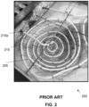
- Figures 1 and 2 illustrate examples of moulds for the fabrication of an item which are known in the art.
- the moulding structure of the moulds of Figures 1 and 2 is not illustrated to better show the inner composition of the mould.
- the elongate tube 110 is fixed to the metal structure 105 such that a first end 110a of the tube is located adjacent the centre of the grid of the metal structure 105 and a second end 110b may project outside of the perimeter of the metal structure 105.
- the elongate tube 110 is wound to form a spiral shape.
- the elongate tube 110 is wound such that the first end 110a is located at the base of the three-dimensional bowl structure defined by the curved edges of the metal structure 105, and the elongate tube 110 is fixed to the folded edges 115 of the metal structure 105 as the diameter of the spiral increases towards the second end 110b.
- Figure 2 depicts a second example of a mould 200 comprising a metal structure 205 and a plastic elongate tube 210.
- the metal structure 205 comprises a metallic wire mesh formed from twisted metal wire comprising hexagonal openings. No folded edges are present, and instead the metal structure 205 is deformed to provide a three-dimensional bowl structure wherein all surfaces of the structure comprise mesh.
- the plastic elongate tube 210 is fixed to the metal structure 205 at a plurality of locations and the elongate tube 210 is wound about the metal structure 205 to form a spiral shape.
- a first end 210a of the elongate tube 210 is located outside the perimeter of the metal structure 205.
- Both examples of Figures 1 and 2 may be surrounded by a moulding structure, such as gypsum, to form the mould 100, 200.
- a moulding structure such as gypsum
- the plastic elongate tubes 110, 210 and metal structures 105, 205 provide a basis around which the gypsum can be added, and the gypsum material itself is crafted to form the external shape of the mould.
- the moulds 100, 200 of the prior art comprise gypsum, metal and plastic, it is challenging to assemble the moulds 100, 200 and also challenging to recycle the materials of the moulds 100, 200 at the end of use.
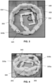
- a mould 300 for the fabrication of an item comprising a porous drying structure 305.
- the porous drying structure 305 comprises a set inorganic material, such as a gypsum composition.
- the porous drying structure 305 comprises a plurality of interconnected tubes 320 such that a continuous cavity 325 projects through the porous drying structure 305.
- the cavity 325 is located centrally within each tube 320 and has a substantially cylindrical cross-section. In this embodiment, the diameter of the cavity 325 is 5 mm. Air, preferably compressed air can be passed through the cavity 325 and into the pores of the porous drying structure 305. As the inner walls of the porous drying structure 305 defining the cavity 325 are porous, a fluid pathway is created from the cavity into the porous drying structure 305.
- the plurality of interconnected tubes 320 comprises a plurality of cylindrical straight members 330 and a plurality of generally cylindrical angled members 335.
- the outer diameter of the plurality of straight members 330 is greater than the outer diameter of the plurality of angled members 335 to improve strength of the porous drying structure 305.
- the plurality of angled members 335 comprise a plurality of first angled members 335a comprising a central bend with an angle ⁇ of 135 degrees and a plurality of second angled members 335b comprising a central bend with an angle ⁇ of 90 degrees, as illustrated in Figure 7 .
- a first end 355 of an angled member 335 of the plurality of angled members 335 is configured to be housed within the cavity 325 of a straight member 330 of the plurality of straight members 330 with an interference fit.
- a second end 360 of an angled member 335 is configured to be housed within the cavity 325 of a straight member 330 with an interference fit.
- the first end 355 and second end 360 may be manufactured by removing material from the outer surface of each end 355, 360 to permit an interference fit between the angled member 335 and the straight members 330.
- the plurality of straight members 330 and plurality of angled members 335 are connected such that a straight member 330 is connected to an angled member 335 on both sides and an angled member 335 is connected to a straight member on both sides, such that pattern of the interconnected tubes 320 is sequential. In this way, the cavity 325 is continuous through the porous drying structure 305.
- the interconnected tubes 320 may be manufactured using additive manufacturing techniques, such as three-dimensional (3D) printing, or by moulding.
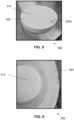
- the mould 300 further comprises a moulding structure 310 comprising a gypsum composition, as illustrated in Figures 5 and 6 .
- the moulding structure 310 is cylindrical and comprises a cylindrical central protrusion 315.
- the porous drying structure 305 is at least partially enclosed within the moulding structure 310. As illustrated in Figure 6 , at least 97% of the porous drying structure 305 by volume is enclosed within the moulding structure 310. It is envisaged that the porous drying structure 305 may be entirely enclosed within the moulding structure 310.
- the moulding structure 310 comprises at least one moulding surface (not pictured) configured to shape the item to be moulded.
- the at least one moulding surface comprises the internal surfaces of the moulding structure 310, such that a mould cavity (not pictured) is formed within the moulding structure 310, the mould cavity defined by the at least one moulding surface.
- the porous drying structure 305 does not intersect, interrupt or otherwise disrupt the moulding surface, such that the porous drying structure 305 does not influence the shape of the mould cavity.
- a first end 305a of the drying structure is located adjacent the base surface 345 of the moulding structure 310, as illustrated in Figure 6 .
- a second end 305b of the drying structure is located outside the outer perimeter of the top surface 350 of the moulding structure 310. In this way, the second end 305b can be connected to a fluid source, such as an air source configured to pump air into the cavity 325.
- the cavity 325 is continuous from the first end 305a to the second end 305b of the porous drying structure 305.
- the porous drying structure 305 is spiral in shape, with approximately three turns between the first end 305a and the second end 205b.
- the plurality of angled members 335 permit the porous drying structure 305 to be positioned in a spiral shape, without deformation of the interconnected tubes 320.
- the mould 300 further comprises a support structure 340 connected to the porous drying structure 305.
- the support structure 340 is partially enclosed within the moulding structure 310.
- the support structure 340 comprises a plurality of blocks 365 located between adjacent turns of the spiral shape of the porous drying structure 305. Each block 365 is connected to a first angled member 335a and a second angled member 335a. In this way, the support structure 340 connects angled members 335a to angled members 335a in adjacent turns of the spiral.
- the support structure 340 therefore improves stability and strength of the mould 300.
- Each block 365 is configured to partially encase a portion of the corresponding angled member 335a with an interference fit such that the angled member 335a is connected to the block 365 and inhibited from moving in at least a first plane. Further, friction between the surfaces of the block 365 and the angled member 335a improve the strength of the connection between the block 365 and the angled member 335a.
- calcium sulphate paste may be applied to the block 365 and angled member 335a to improve the connection.
- the support structure 340 comprises a set inorganic material to improve ease of recycling using generic bulk processes.
- the moulding structure 310, porous drying structure 305 and support structure 340 comprise materials with similar properties and so the mould 300 is easy to recycle when decommissioned. Namely, the mould 300 can be recycled using generic bulk processes, with the porous drying structure 305 forming an impurity within the recycled moulding structure 310.
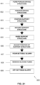
- the method 400 is a method of forming a mould 300.
- the method 400 comprises forming 401 a porous drying structure 305 comprising a set inorganic material.
- the method 400 further comprises pouring 402 a settable slurry such that the settable slurry at least partially encloses the porous drying structure 305.
- the method 400 further comprises drying 403 the settable slurry to form a moulding structure 310 comprising gypsum.
- Air preferably compressed air can be passed through the cavity 325 and subsequently through the pores of the porous drying structure 305. In this way, air penetrates the porous drying structure 305 improving the ease and speed of drying of the porous drying structure 305. Water and other fluid can be driven out of the porous drying structure 305 by the air entering the cavity 325 and the pores of the porous drying structure 305.
- the ability to pass air through the porous drying structure 305 allows the porosity of the moulding structure 310 to be optimized during the manufacturing process, thereby increasing the speed which water can be removed from the mould 300. As such, the interval required between successive moulding processes may be reduced.
- Pore Volume PV S R m 1 ⁇ m 0 m 0 S W
- Pore Volume % PV m 1 ⁇ m 0 V ⁇ 100
- a second embodiment of a mould 500 for the fabrication of an item according to the first aspect of the present invention is depicted.
- the mould 500 comprising a porous drying structure 505.
- the porous drying structure 505 comprises a set inorganic material, such as a gypsum composition, and is substantially identical to the porous drying structure 305 of the first embodiment.
- a first end 505a of the drying structure 505 is located adjacent the base moulding surface 545b of the housing 580, as illustrated in Figure 18 .
- a second end 505b of the drying structure 505 is located outside the outer perimeter of a top surface 550 of the housing 580. In this way, the second end 505b can be connected to a fluid source, such as an air source configured to pump air into the continuous cavity of the drying structure 505.
- the method 600 further comprises securing 604 the support structure 540 to the scaffolding 570, such that the support structure 540 is fixed in a position wherein the support structure 540 does not contact the housing 580.
- Attaching and securing distal ends 565a of the silicone tubes 565 to the scaffolding 570 places the silicone tubes 565 under tension such that the porous drying structure 505 is not raised from its resting position within the housing 580 and remains in contact with the with housing 580, as illustrated in Figure 12 .
- the method 600 further comprises pouring 607 a settable slurry 590 such that the settable slurry 590 entirely encloses the porous drying structure 505.
- the porous drying structure 505 may float in the denser settable slurry 590, necessitating the need to manual hold the support structure 540 in place.
- the user may then apply a force to the elongate rigid members 585 to ensure the porous drying structure 505 and support structure 540 remain in position while the settable slurry 590 sets.
- the method 600 further comprises removing 608 the plurality of silicone tubes 565 from the settable slurry 590.
- removing 608 the plurality of silicone tubes 565 from the settable slurry 590 occurs between 15 to 40 minutes after mixing and pouring the settable slurry 590 in step 607.
- the silicone tubes 565 can be easily removed from the settable slurry 590 as they are not fixed to the porous drying structure 505.
- the external elements used to fix the porous drying structure 505 in place are no longer required and so are removed, such as for re-use or disposal.
- the moulding structure 510 is therefore free of any plastic, metal or other external element used during the manufacturing process.
- FIG. 16 and 17 An example of removal of the silicone tubes 565 from the settable slurry 590 is depicted in Figures 16 and 17 .
- the silicone tubes 540 can be untied, released or otherwise separated from the scaffolding 570, and the scaffolding 570 can be removed, as illustrated in Figure 16 .
- the silicone tubes 540 can then be pulled, and removed, from the settable slurry 590 in direction Z via silicone tube holes 595 formed wherein the tubes projected from the surface of the settable slurry 590 prior to setting. Removal of the silicone tubes 540 is assisted by the lack of convoluted pathway the silicone tubes 540 form within the settable slurry 590. Channels within the set moulding structure 510 may remain, as illustrated in Figure 20 , wherein the silicone tubes 540 were once present. In this way, the settable mould is free of plastic and can be recycled at the end of life.
- the silicone tubes 565 can be re-used in a subsequent iteration of the method 600 and/or recycled separately to the moulding structure 510
- Air preferably compressed air can be passed through the cavity and subsequently through the pores of the porous drying structure 505. In this way, air penetrates the porous drying structure 505 improving the ease and speed of drying of the porous drying structure 505. Water and other fluid can be driven out of the porous drying structure 505 by the air entering the cavity 525 and the pores of the porous drying structure 505.
- the ability to pass air through the porous drying structure 505 allows the porosity of the housing 580 to be optimized during the manufacturing process, thereby increasing the speed which water can be removed from the mould 500. As such, the interval required between successive moulding processes may be reduced.
- the portion of the elongate rigid members 585 protruding from the moulding structure 510 may be cut such that they are flush with the exterior surface of the moulding structure 510.
- the U-shape of the silicone tubes 565 improve ease of removal of the silicone tubes 565 after the moulding structure 510 is set.
Landscapes
- Engineering & Computer Science (AREA)
- Manufacturing & Machinery (AREA)
- Chemical & Material Sciences (AREA)
- Ceramic Engineering (AREA)
- Mechanical Engineering (AREA)
- Producing Shaped Articles From Materials (AREA)
Priority Applications (2)
| Application Number | Priority Date | Filing Date | Title |
|---|---|---|---|
| EP23307270.1A EP4574372A1 (fr) | 2023-12-19 | 2023-12-19 | Moule en plâtre, son procédé de fabrication et structure de séchage poreuse à utiliser dans ledit moule |
| PCT/EP2024/082532 WO2025131473A1 (fr) | 2023-12-19 | 2024-11-15 | Moule en gypse, son procédé de fabrication et structure de séchage poreuse destinée à être utilisée dans ledit moule |
Applications Claiming Priority (1)
| Application Number | Priority Date | Filing Date | Title |
|---|---|---|---|
| EP23307270.1A EP4574372A1 (fr) | 2023-12-19 | 2023-12-19 | Moule en plâtre, son procédé de fabrication et structure de séchage poreuse à utiliser dans ledit moule |
Publications (1)
| Publication Number | Publication Date |
|---|---|
| EP4574372A1 true EP4574372A1 (fr) | 2025-06-25 |
Family
ID=89574011
Family Applications (1)
| Application Number | Title | Priority Date | Filing Date |
|---|---|---|---|
| EP23307270.1A Pending EP4574372A1 (fr) | 2023-12-19 | 2023-12-19 | Moule en plâtre, son procédé de fabrication et structure de séchage poreuse à utiliser dans ledit moule |
Country Status (2)
| Country | Link |
|---|---|
| EP (1) | EP4574372A1 (fr) |
| WO (1) | WO2025131473A1 (fr) |
Citations (10)
| Publication number | Priority date | Publication date | Assignee | Title |
|---|---|---|---|---|
| GB1381479A (en) * | 1971-03-18 | 1975-01-22 | Batchelor P J Twigg E | Moulds |
| SU662349A1 (ru) * | 1977-04-11 | 1979-05-25 | Предприятие П/Я А-7840 | Форма дл лить керамических изделий |
| JPS63288705A (ja) * | 1987-05-20 | 1988-11-25 | Inax Corp | 精密寸法の泥漿鋳込用成形型 |
| JPH04109104U (ja) * | 1991-03-04 | 1992-09-21 | 東陶機器株式会社 | 石膏型 |
| JPH04270602A (ja) * | 1991-02-26 | 1992-09-28 | Ngk Insulators Ltd | 高圧鋳込み成形型及びそれを用いた成形方法 |
| US5556587A (en) * | 1989-06-21 | 1996-09-17 | Ngk Insulators, Ltd. | Method of manufacturing ceramics using a porous mold |
| US20030134005A1 (en) * | 2001-03-09 | 2003-07-17 | Vasco Mazzanti | Moulding element for forming articles by slip casting with clay or the like and a method for its manufacture |
| CN101700674A (zh) * | 2009-10-24 | 2010-05-05 | 潍坊华美精细技术陶瓷有限公司 | 石膏模具的快速干燥方法 |
| JP2014188771A (ja) * | 2013-03-27 | 2014-10-06 | Ngk Insulators Ltd | 懸垂碍子成形型 |
| CN204640463U (zh) * | 2015-04-15 | 2015-09-16 | 江苏兰谷环保科技股份有限公司 | 一种快速排水石膏模具 |
Family Cites Families (3)
| Publication number | Priority date | Publication date | Assignee | Title |
|---|---|---|---|---|
| FR2145066A5 (en) * | 1971-07-08 | 1973-02-16 | Sfec | Ceramic coated plaster mould - has longer life |
| JPS5333962B2 (fr) * | 1972-09-06 | 1978-09-18 | ||
| BR9003156A (pt) * | 1990-06-29 | 1992-01-07 | Ideal Standard Wabco Ind Comer | Processo para a obtencao de partes de um molde de gesso;molde para a fabricacao de um artigo ceramico e processo para a secagem de um molde de gesso |
-
2023
- 2023-12-19 EP EP23307270.1A patent/EP4574372A1/fr active Pending
-
2024
- 2024-11-15 WO PCT/EP2024/082532 patent/WO2025131473A1/fr active Pending
Patent Citations (10)
| Publication number | Priority date | Publication date | Assignee | Title |
|---|---|---|---|---|
| GB1381479A (en) * | 1971-03-18 | 1975-01-22 | Batchelor P J Twigg E | Moulds |
| SU662349A1 (ru) * | 1977-04-11 | 1979-05-25 | Предприятие П/Я А-7840 | Форма дл лить керамических изделий |
| JPS63288705A (ja) * | 1987-05-20 | 1988-11-25 | Inax Corp | 精密寸法の泥漿鋳込用成形型 |
| US5556587A (en) * | 1989-06-21 | 1996-09-17 | Ngk Insulators, Ltd. | Method of manufacturing ceramics using a porous mold |
| JPH04270602A (ja) * | 1991-02-26 | 1992-09-28 | Ngk Insulators Ltd | 高圧鋳込み成形型及びそれを用いた成形方法 |
| JPH04109104U (ja) * | 1991-03-04 | 1992-09-21 | 東陶機器株式会社 | 石膏型 |
| US20030134005A1 (en) * | 2001-03-09 | 2003-07-17 | Vasco Mazzanti | Moulding element for forming articles by slip casting with clay or the like and a method for its manufacture |
| CN101700674A (zh) * | 2009-10-24 | 2010-05-05 | 潍坊华美精细技术陶瓷有限公司 | 石膏模具的快速干燥方法 |
| JP2014188771A (ja) * | 2013-03-27 | 2014-10-06 | Ngk Insulators Ltd | 懸垂碍子成形型 |
| CN204640463U (zh) * | 2015-04-15 | 2015-09-16 | 江苏兰谷环保科技股份有限公司 | 一种快速排水石膏模具 |
Also Published As
| Publication number | Publication date |
|---|---|
| WO2025131473A1 (fr) | 2025-06-26 |
Similar Documents
| Publication | Publication Date | Title |
|---|---|---|
| US4528152A (en) | Method for obtaining drain-cast hollow articles for ceramic ware | |
| US4887789A (en) | Form for molding columns | |
| US9993941B2 (en) | Methods and systems for the formation and use of reduced weight building blocks forms | |
| EP4574372A1 (fr) | Moule en plâtre, son procédé de fabrication et structure de séchage poreuse à utiliser dans ledit moule | |
| CN111255157A (zh) | 一种楼层临边构造柱混凝土浇筑装置及施工方法 | |
| US3676976A (en) | Roof structure | |
| GB2031331A (en) | Method and apparatus for producing reinforced concrete panels | |
| CN112144696B (zh) | 一种装配式钢结构建筑剪力墙及其安装方法 | |
| CN211120385U (zh) | 一种瓷砖生产干燥用放置架 | |
| JP2011051200A (ja) | 軽量気泡コンクリートパネルの製造方法 | |
| CN214144668U (zh) | 一种大面积单元排混凝土现浇模具 | |
| SU1576337A1 (ru) | Устройство дл формовани криволинейных изделий | |
| KR100697302B1 (ko) | 교량 거푸집 탈착방법 및 다단식 거푸집 | |
| JPS63284332A (ja) | ド−ムの構築工法及びその型枠用袋体 | |
| CN216340108U (zh) | 一种用于承受拉力的钢结构支座 | |
| RU65424U1 (ru) | Форма для формирования массивов из бетонов | |
| CN214238724U (zh) | 新型混凝土试件成型模具 | |
| EP1590141A1 (fr) | Moule a parois laterales flexibles dotees d'elements de support pour mouler des produits de construction | |
| CN112160591B (zh) | 建筑房梁用加固装置 | |
| EP4707486A2 (fr) | Dispositif de fixation pour mur composite | |
| JP2000088720A (ja) | 脱水コンクリート強度管理用テストピースの作成方法及び作成装置 | |
| KR100352331B1 (ko) | 철근 받침대 | |
| CN210163767U (zh) | 一种水溶式沉降临时支座 | |
| JP2004284302A (ja) | Alcパネルの製造方法 | |
| RU2299802C2 (ru) | Распалубщик для бетонных изделий |
Legal Events
| Date | Code | Title | Description |
|---|---|---|---|
| PUAI | Public reference made under article 153(3) epc to a published international application that has entered the european phase |
Free format text: ORIGINAL CODE: 0009012 |
|
| STAA | Information on the status of an ep patent application or granted ep patent |
Free format text: STATUS: THE APPLICATION HAS BEEN PUBLISHED |
|
| AK | Designated contracting states |
Kind code of ref document: A1 Designated state(s): AL AT BE BG CH CY CZ DE DK EE ES FI FR GB GR HR HU IE IS IT LI LT LU LV MC ME MK MT NL NO PL PT RO RS SE SI SK SM TR |
|
| STAA | Information on the status of an ep patent application or granted ep patent |
Free format text: STATUS: REQUEST FOR EXAMINATION WAS MADE |
|
| 17P | Request for examination filed |
Effective date: 20251222 |