EP4574385A1 - Formpresswerkzeug und verfahren zur herstellung einer faserpulpeschale unter verwendung des werkzeugs - Google Patents
Formpresswerkzeug und verfahren zur herstellung einer faserpulpeschale unter verwendung des werkzeugs Download PDFInfo
- Publication number
- EP4574385A1 EP4574385A1 EP23219025.6A EP23219025A EP4574385A1 EP 4574385 A1 EP4574385 A1 EP 4574385A1 EP 23219025 A EP23219025 A EP 23219025A EP 4574385 A1 EP4574385 A1 EP 4574385A1
- Authority
- EP
- European Patent Office
- Prior art keywords
- mould element
- female mould
- fibrous pulp
- male
- female
- Prior art date
- Legal status (The legal status is an assumption and is not a legal conclusion. Google has not performed a legal analysis and makes no representation as to the accuracy of the status listed.)
- Pending
Links
Images






Classifications
-
- D—TEXTILES; PAPER
- D21—PAPER-MAKING; PRODUCTION OF CELLULOSE
- D21J—FIBREBOARD; MANUFACTURE OF ARTICLES FROM CELLULOSIC FIBROUS SUSPENSIONS OR FROM PAPIER-MACHE
- D21J3/00—Manufacture of articles by pressing wet fibre pulp, or papier-mâché, between moulds
-
- B—PERFORMING OPERATIONS; TRANSPORTING
- B29—WORKING OF PLASTICS; WORKING OF SUBSTANCES IN A PLASTIC STATE IN GENERAL
- B29C—SHAPING OR JOINING OF PLASTICS; SHAPING OF MATERIAL IN A PLASTIC STATE, NOT OTHERWISE PROVIDED FOR; AFTER-TREATMENT OF THE SHAPED PRODUCTS, e.g. REPAIRING
- B29C43/00—Compression moulding, i.e. applying external pressure to flow the moulding material; Apparatus therefor
- B29C43/02—Compression moulding, i.e. applying external pressure to flow the moulding material; Apparatus therefor of articles of definite length, i.e. discrete articles
- B29C43/021—Compression moulding, i.e. applying external pressure to flow the moulding material; Apparatus therefor of articles of definite length, i.e. discrete articles characterised by the shape of the surface
-
- B—PERFORMING OPERATIONS; TRANSPORTING
- B29—WORKING OF PLASTICS; WORKING OF SUBSTANCES IN A PLASTIC STATE IN GENERAL
- B29C—SHAPING OR JOINING OF PLASTICS; SHAPING OF MATERIAL IN A PLASTIC STATE, NOT OTHERWISE PROVIDED FOR; AFTER-TREATMENT OF THE SHAPED PRODUCTS, e.g. REPAIRING
- B29C43/00—Compression moulding, i.e. applying external pressure to flow the moulding material; Apparatus therefor
- B29C43/02—Compression moulding, i.e. applying external pressure to flow the moulding material; Apparatus therefor of articles of definite length, i.e. discrete articles
- B29C43/14—Compression moulding, i.e. applying external pressure to flow the moulding material; Apparatus therefor of articles of definite length, i.e. discrete articles in several steps
-
- B—PERFORMING OPERATIONS; TRANSPORTING
- B65—CONVEYING; PACKING; STORING; HANDLING THIN OR FILAMENTARY MATERIAL
- B65D—CONTAINERS FOR STORAGE OR TRANSPORT OF ARTICLES OR MATERIALS, e.g. BAGS, BARRELS, BOTTLES, BOXES, CANS, CARTONS, CRATES, DRUMS, JARS, TANKS, HOPPERS, FORWARDING CONTAINERS; ACCESSORIES, CLOSURES, OR FITTINGS THEREFOR; PACKAGING ELEMENTS; PACKAGES
- B65D1/00—Rigid or semi-rigid containers having bodies formed in one piece, e.g. by casting metallic material, by moulding plastics, by blowing vitreous material, by throwing ceramic material, by moulding pulped fibrous material or by deep-drawing operations performed on sheet material
- B65D1/34—Trays or like shallow containers
-
- B—PERFORMING OPERATIONS; TRANSPORTING
- B29—WORKING OF PLASTICS; WORKING OF SUBSTANCES IN A PLASTIC STATE IN GENERAL
- B29C—SHAPING OR JOINING OF PLASTICS; SHAPING OF MATERIAL IN A PLASTIC STATE, NOT OTHERWISE PROVIDED FOR; AFTER-TREATMENT OF THE SHAPED PRODUCTS, e.g. REPAIRING
- B29C43/00—Compression moulding, i.e. applying external pressure to flow the moulding material; Apparatus therefor
- B29C43/02—Compression moulding, i.e. applying external pressure to flow the moulding material; Apparatus therefor of articles of definite length, i.e. discrete articles
- B29C43/14—Compression moulding, i.e. applying external pressure to flow the moulding material; Apparatus therefor of articles of definite length, i.e. discrete articles in several steps
- B29C2043/141—Compression moulding, i.e. applying external pressure to flow the moulding material; Apparatus therefor of articles of definite length, i.e. discrete articles in several steps for making single layer articles
- B29C2043/144—Compression moulding, i.e. applying external pressure to flow the moulding material; Apparatus therefor of articles of definite length, i.e. discrete articles in several steps for making single layer articles using different moulds, i.e. the layer is compressed in consecutive steps by using different moulds for each portion of the article
-
- B—PERFORMING OPERATIONS; TRANSPORTING
- B29—WORKING OF PLASTICS; WORKING OF SUBSTANCES IN A PLASTIC STATE IN GENERAL
- B29L—INDEXING SCHEME ASSOCIATED WITH SUBCLASS B29C, RELATING TO PARTICULAR ARTICLES
- B29L2031/00—Other particular articles
- B29L2031/712—Containers; Packaging elements or accessories, Packages
Definitions
- the present invention relates to a moulding tool and to a method for forming a fibrous pulp tray using the tool.
- the fibrous pulp tray manufactured by the described compression moulding tool should in the present context be understood to be a container having a floor portion and a number of sidewalls so that it can contain a product.
- the manufactured tray will also have a substantially horizontal upper flange extending outwards from the sidewalls.
- Trays for food packaging typically comprises four sidewalls providing a rectangular container, but other shapes are not excluded from being manufactured using the described tool.
- a tray may also be referred to as a container, box, carton, package, and the like. Accordingly, the described moulds are adapted to manufacture such trays.
- That the upper portion of the second female mould element is substantially horizontal means that there is no significant angle even if the upper portion may deviate somewhat from the horizontal plane.
- a deviation in the range of ⁇ 5° from the horizontal plane can in the present context be considered to be substantially horizontal.
- the outward sloping sidewalls of the first female mould element and the outward sloping sidewalls of the second female mould element are of the same height. This has the effect that the entire portion of the tray which will subsequently form the flange has the second draft angle after being pressed between the first set of mould elements. Thereby, there is only one portion of the tray which is being reformed in the second moulding step.
- the first female mould element and the first male mould elements are configured to be used in a forming step and the second female mould element and the second male mould element are configured to be used in a hot-pressing step.
- the first forming step may be a so called cold-forming or wet-forming forming step where water of the pulp is removed by pressing the pulp between the first male and female mould without heating the moulds, thereby reducing the water content of the pulp.
- heating is employed to further reduce the water content of the tray.
- At least one of the second female mould element and the second male moulding element may thereby comprise a heating arrangement configured to heat and dry the fibrous pulp product.
- the tray may have a sufficiently high-dry content to be ready for use.
- the compression moulding tool further comprises: a third female mould element having a floor, outward sloping sidewalls, and an upper sidewall portion located above and adjacent to the sidewalls, the upper sidewall portion having a third draft angle which is larger than the second draft angle; and a third male mould element configured to press against the third female mould element to compress a fibrous pulp product located therebetween, the third male mould element having a shape matching the shape of the third female mould element.
- the third set of mould elements are provided with an upper sidewall angle having an intermediate draft angle which is larger than the first angle, but which is not the horizontal alignment of the upper portion of the second mould elements.
- the described third set of mould elements is thereby configured to be used between the first and second sets of moulds so that the portion of the tray to form the horizontal flange is formed in three steps to further improve the quality of the tray and reducing the risk of damaging the tray during formation of the flange.
- the third draft angle is preferably somewhere in the middle between the second draft angle and 90° so that transition between the sidewall and the flange of the tray is formed by bending down the flange in two separate and approximately equal steps.
- At least one of the first female mould element and the first male mould element comprises a water permeable filter arranged in and configured to follow the surface of the mould element, the filter being configured to retain pulp fibers.
- the water permeable filter may for example be a wire mesh which is a durable alterative for retaining the pulp fibers while draining away the water.
- the wire mesh can be a single layer wire mesh, a double layer wire mesh or any other type of multi-layer mesh.
- the water permeable filter may be a wire cloth, a screen, porous aluminum, or any other suitable water permeable filtering means known to the skilled person.
- At least one of the first female mould element and the first male mould element comprises a plurality of drainage channels.
- the drainage channels are configured to drain water from the pulp in a first pressing step, and the drainage channels are preferably connected to a pump forming a vacuum to draw water from the pulp.
- a portion of the first female mould element forming a transition between the outward sloping sidewalls and the upper sidewall portion has a curvature.
- a convex portion having a curvature at the transition between the sidewall and the upper sidewall portion, and a corresponding concave portion for the first male mould element will avoid a sharp angle in the transition from the sidewall to the flange of a tray. There is thus less risk of breaking the tray when having a rounded transition in moulds.
- a corresponding rounded transition may be used also for the second set of moulds between the sidewalls and the horizontal portion.
- a method for manufacturing a fibrous pulp tray comprising: depositing a fibrous pulp suspension in a first female mould element having a floor, outward sloping sidewalls having a first draft angle, and an upper sidewall portion located above and adjacent to the sidewalls, the upper sidewall portion having a second draft angle which is larger than the first draft angle; pressing a first male mould element against the first female mould element to dewater the fibrous pulp suspension such that a fibrous pulp product is formed therebetween, the male mould element having a surface profile matching the shape of the first female mould element; moving the fibrous pulp product from the first female mould element to a second female mould element having a floor, outward sloping sidewalls having the first draft angle, and an upper portion located above and adjacent to the sidewalls, wherein the upper portion of the second female mould element is substantially horizontal; pressing a second male mould element against the second female mould element such that the fibrous pulp product is formed therebetween, the second male mould element having a shape matching
- the method further comprises draining water from the fibrous pulp material through drainage channels of at least one of the first female mould element and the first male mould element.
- the fibrous pulp product is preferably dried to a dry content in the range of 20% to 45% before the step of pressing the fibrous pulp product between the second male and female mould elements.
- the tray may be difficult to move, and additional drying steps may be required to reach a final desired dry content of the tray, and with a too high dry content the risk of breaking the tray in the second step when the flange portion is bent down is increased.
- depositing the fibrous pulp suspension comprises dipping the first female mould element in a container comprising a fibrous pulp suspension.
- a fibrous pulp suspension comprises dipping the first female mould element in a container comprising a fibrous pulp suspension.
- other methods of depositing a fibrous pulp are equally possible such as spraying, dipping an upside-down mould in a fibrous pulp suspension, deposition from above etc.
- the method advantageously comprises laminating an inside of the fibrous pulp product with a plastic film.
- the lamination process is improved by means of the smooth inner surface of the tray.
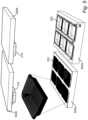
- FIGs. 1 and 2 schematically illustrate a compression moulding tool 100 for manufacturing a fibrous pulp tray
- Fig. 1 illustrates a first set of mould elements
- Fig. 2 illustrates a second set of mould elements, each set comprising a male and a female mould element.
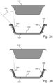
- a cross section of the two sets of mould element is shown in Fig. 3 , further illustrating details of the mould elements.
- Fig. 4 illustrating an example fibrous pulp tray manufactured by the described compression moulding tool.
- the formation of the sharp transition between the sidewalls 404 and the flange 406 of the tray 400 will thus be performed in two separate steps to reduce the risk of damage or defects in the tray 400.
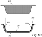
- Figs. 6A-C illustrate an example embodiment of a compression moulding tool further comprising a third female mould element 602 illustrated in Fig. 6B.
- Fig. 6A illustrates the first set of mould elements 102, 110 and
- Fig. 6C illustrates the second set of mould elements 202, 210.
- the fibrous pulp product is moved 804 from the first female mould element 102 to the second female mould element 202, for example by using vacuum to lift the fibrous pulp product from one station to the next.
- the following step comprises pressing 808 a second male mould element 210 against the second female mould element 202 such that the fibrous pulp product 400 is formed therebetween, thereby forming a fibrous pulp product 600 having a floor 402, sidewalls 404 and an upper flange 406 extending from the sidewalls.
- the method may further comprise laminating an inside of the fibrous pulp tray 400 with a plastic film by arranging a plastic film over the tray and heating the film so that it softens and adapts to the shape of the inner surface of the tray 400.
Landscapes
- Engineering & Computer Science (AREA)
- Mechanical Engineering (AREA)
- Ceramic Engineering (AREA)
- Manufacturing & Machinery (AREA)
- Containers Having Bodies Formed In One Piece (AREA)
Priority Applications (2)
| Application Number | Priority Date | Filing Date | Title |
|---|---|---|---|
| EP23219025.6A EP4574385A1 (de) | 2023-12-21 | 2023-12-21 | Formpresswerkzeug und verfahren zur herstellung einer faserpulpeschale unter verwendung des werkzeugs |
| PCT/EP2024/086256 WO2025132087A1 (en) | 2023-12-21 | 2024-12-13 | Compression moulding tool and method for manufacturing a fibrous pulp tray using the tool |
Applications Claiming Priority (1)
| Application Number | Priority Date | Filing Date | Title |
|---|---|---|---|
| EP23219025.6A EP4574385A1 (de) | 2023-12-21 | 2023-12-21 | Formpresswerkzeug und verfahren zur herstellung einer faserpulpeschale unter verwendung des werkzeugs |
Publications (1)
| Publication Number | Publication Date |
|---|---|
| EP4574385A1 true EP4574385A1 (de) | 2025-06-25 |
Family
ID=89430328
Family Applications (1)
| Application Number | Title | Priority Date | Filing Date |
|---|---|---|---|
| EP23219025.6A Pending EP4574385A1 (de) | 2023-12-21 | 2023-12-21 | Formpresswerkzeug und verfahren zur herstellung einer faserpulpeschale unter verwendung des werkzeugs |
Country Status (2)
| Country | Link |
|---|---|
| EP (1) | EP4574385A1 (de) |
| WO (1) | WO2025132087A1 (de) |
Citations (6)
| Publication number | Priority date | Publication date | Assignee | Title |
|---|---|---|---|---|
| WO2006057610A2 (en) * | 2004-11-26 | 2006-06-01 | Pakit International Trading Company Inc | A method and a machine for making fibre products from stock and a new type of fibre product |
| WO2010124300A1 (en) * | 2009-04-24 | 2010-10-28 | Seanet Development, Inc. | Processes for molding pulp paper containers and lids |
| US20160368235A1 (en) * | 2015-06-16 | 2016-12-22 | Golden Arrow Printing Co., Ltd. | Hot pressing mold for pulp molding and manufacturing method thereof |
| WO2022066149A1 (en) * | 2020-09-22 | 2022-03-31 | Hewlett-Packard Development Company, L.P. | Transfer screens to be 3d fabricated with determined pore placements |
| WO2022248643A1 (en) * | 2021-05-27 | 2022-12-01 | Ftt S.R.L. | Selective double layer moulding process and apparatus |
| WO2022253491A1 (en) * | 2021-05-31 | 2022-12-08 | Rottneros Packaging Ab | Compression moulding tool and method for manufacturing a fibrous pulp tray using the tool |
-
2023
- 2023-12-21 EP EP23219025.6A patent/EP4574385A1/de active Pending
-
2024
- 2024-12-13 WO PCT/EP2024/086256 patent/WO2025132087A1/en active Pending
Patent Citations (6)
| Publication number | Priority date | Publication date | Assignee | Title |
|---|---|---|---|---|
| WO2006057610A2 (en) * | 2004-11-26 | 2006-06-01 | Pakit International Trading Company Inc | A method and a machine for making fibre products from stock and a new type of fibre product |
| WO2010124300A1 (en) * | 2009-04-24 | 2010-10-28 | Seanet Development, Inc. | Processes for molding pulp paper containers and lids |
| US20160368235A1 (en) * | 2015-06-16 | 2016-12-22 | Golden Arrow Printing Co., Ltd. | Hot pressing mold for pulp molding and manufacturing method thereof |
| WO2022066149A1 (en) * | 2020-09-22 | 2022-03-31 | Hewlett-Packard Development Company, L.P. | Transfer screens to be 3d fabricated with determined pore placements |
| WO2022248643A1 (en) * | 2021-05-27 | 2022-12-01 | Ftt S.R.L. | Selective double layer moulding process and apparatus |
| WO2022253491A1 (en) * | 2021-05-31 | 2022-12-08 | Rottneros Packaging Ab | Compression moulding tool and method for manufacturing a fibrous pulp tray using the tool |
Also Published As
| Publication number | Publication date |
|---|---|
| WO2025132087A1 (en) | 2025-06-26 |
Similar Documents
| Publication | Publication Date | Title |
|---|---|---|
| EP4098420B1 (de) | Formpresswerkzeug und verfahren zur herstellung einer faserstoffschale unter verwendung des werkzeugs | |
| US8777046B2 (en) | Drink cup with rolled brim | |
| CA2715877C (en) | A device and a method for compression moulding of a fibre tray | |
| US10711404B2 (en) | Pulp molding apparatus and molds for use therein | |
| EP4574385A1 (de) | Formpresswerkzeug und verfahren zur herstellung einer faserpulpeschale unter verwendung des werkzeugs | |
| JP3153322B2 (ja) | 抄造容器の製造方法 | |
| TWI588319B (zh) | 濕紙塑撈漿系統、濕紙塑產品及濕紙塑產品的成形方法 | |
| CN112626929A (zh) | 一种吸浆均匀的纸浆模塑吸浆模具及用途 | |
| JP2000034699A (ja) | パルプモウルド成形品の加熱プレス用型及びパルプモウルド成形品の製造方法 | |
| CN211848633U (zh) | 一种纸浆成型产品解决背面挂浆系统 | |
| US12351367B2 (en) | Pulp-molded cup lid with leakproof structure | |
| EP4650518A1 (de) | Modulares formpresswerkzeug zur herstellung eines faserpulpeprodukts | |
| CN224173124U (zh) | 一种吸浆模具和纸塑缓冲件注塑装置 | |
| CN111041898A (zh) | 一种纸浆成型产品解决背面挂浆系统 | |
| TWI733486B (zh) | 濾芯製作方法 | |
| US12397964B2 (en) | Stick-shaped paper container | |
| CN103276637B (zh) | 酒盒底托成型模具 | |
| JP2001055699A (ja) | パルプモールド成形体の製造方法 | |
| CN115627662A (zh) | 一种多层复合纸浆承重板模塑模具及其加工工艺 | |
| JP2005179885A (ja) | パルプモールド中空成形体の製造方法 | |
| JP2000054297A (ja) | パルプモールド成形品の加熱プレス用型 | |
| JP2000203554A (ja) | 紙製容器及びその製造方法 | |
| JP3249794B2 (ja) | パルプモールド成形体の製造方法 | |
| JPH08209599A (ja) | 繊維材料から成る容器及びその製造方法 | |
| JP2002146700A (ja) | パルプモールド成形体の製造方法 |
Legal Events
| Date | Code | Title | Description |
|---|---|---|---|
| PUAI | Public reference made under article 153(3) epc to a published international application that has entered the european phase |
Free format text: ORIGINAL CODE: 0009012 |
|
| STAA | Information on the status of an ep patent application or granted ep patent |
Free format text: STATUS: THE APPLICATION HAS BEEN PUBLISHED |
|
| AK | Designated contracting states |
Kind code of ref document: A1 Designated state(s): AL AT BE BG CH CY CZ DE DK EE ES FI FR GB GR HR HU IE IS IT LI LT LU LV MC ME MK MT NL NO PL PT RO RS SE SI SK SM TR |
|
| STAA | Information on the status of an ep patent application or granted ep patent |
Free format text: STATUS: REQUEST FOR EXAMINATION WAS MADE |
|
| 17P | Request for examination filed |
Effective date: 20251212 |