EP4574592A1 - Dispositif de commande du freinage d'une remorque - Google Patents
Dispositif de commande du freinage d'une remorque Download PDFInfo
- Publication number
- EP4574592A1 EP4574592A1 EP24220999.7A EP24220999A EP4574592A1 EP 4574592 A1 EP4574592 A1 EP 4574592A1 EP 24220999 A EP24220999 A EP 24220999A EP 4574592 A1 EP4574592 A1 EP 4574592A1
- Authority
- EP
- European Patent Office
- Prior art keywords
- line
- fact
- pressure
- trailer
- electric
- Prior art date
- Legal status (The legal status is an assumption and is not a legal conclusion. Google has not performed a legal analysis and makes no representation as to the accuracy of the status listed.)
- Pending
Links
Images


Classifications
-
- B—PERFORMING OPERATIONS; TRANSPORTING
- B60—VEHICLES IN GENERAL
- B60T—VEHICLE BRAKE CONTROL SYSTEMS OR PARTS THEREOF; BRAKE CONTROL SYSTEMS OR PARTS THEREOF, IN GENERAL; ARRANGEMENT OF BRAKING ELEMENTS ON VEHICLES IN GENERAL; PORTABLE DEVICES FOR PREVENTING UNWANTED MOVEMENT OF VEHICLES; VEHICLE MODIFICATIONS TO FACILITATE COOLING OF BRAKES
- B60T7/00—Brake-action initiating means
- B60T7/12—Brake-action initiating means for automatic initiation; for initiation not subject to will of driver or passenger
- B60T7/20—Brake-action initiating means for automatic initiation; for initiation not subject to will of driver or passenger specially for trailers, e.g. in case of uncoupling of or overrunning by trailer
-
- B—PERFORMING OPERATIONS; TRANSPORTING
- B60—VEHICLES IN GENERAL
- B60D—VEHICLE CONNECTIONS
- B60D1/00—Traction couplings; Hitches; Draw-gear; Towing devices
- B60D1/58—Auxiliary devices
- B60D1/62—Auxiliary devices involving supply lines, electric circuits or the like
- B60D1/64—Couplings or joints therefor
-
- B—PERFORMING OPERATIONS; TRANSPORTING
- B60—VEHICLES IN GENERAL
- B60T—VEHICLE BRAKE CONTROL SYSTEMS OR PARTS THEREOF; BRAKE CONTROL SYSTEMS OR PARTS THEREOF, IN GENERAL; ARRANGEMENT OF BRAKING ELEMENTS ON VEHICLES IN GENERAL; PORTABLE DEVICES FOR PREVENTING UNWANTED MOVEMENT OF VEHICLES; VEHICLE MODIFICATIONS TO FACILITATE COOLING OF BRAKES
- B60T13/00—Transmitting braking action from initiating means to ultimate brake actuator with power assistance or drive; Brake systems incorporating such transmitting means, e.g. air-pressure brake systems
- B60T13/10—Transmitting braking action from initiating means to ultimate brake actuator with power assistance or drive; Brake systems incorporating such transmitting means, e.g. air-pressure brake systems with fluid assistance, drive, or release
- B60T13/66—Electrical control in fluid-pressure brake systems
- B60T13/662—Electrical control in fluid-pressure brake systems characterised by specified functions of the control system components
-
- B—PERFORMING OPERATIONS; TRANSPORTING
- B60—VEHICLES IN GENERAL
- B60T—VEHICLE BRAKE CONTROL SYSTEMS OR PARTS THEREOF; BRAKE CONTROL SYSTEMS OR PARTS THEREOF, IN GENERAL; ARRANGEMENT OF BRAKING ELEMENTS ON VEHICLES IN GENERAL; PORTABLE DEVICES FOR PREVENTING UNWANTED MOVEMENT OF VEHICLES; VEHICLE MODIFICATIONS TO FACILITATE COOLING OF BRAKES
- B60T15/00—Construction arrangement, or operation of valves incorporated in power brake systems and not covered by groups B60T11/00 or B60T13/00
- B60T15/02—Application and release valves
- B60T15/18—Triple or other relay valves which allow step-wise application or release and which are actuated by brake-pipe pressure variation to connect brake cylinders or equivalent to compressed air or vacuum source or atmosphere
- B60T15/20—Triple or other relay valves which allow step-wise application or release and which are actuated by brake-pipe pressure variation to connect brake cylinders or equivalent to compressed air or vacuum source or atmosphere controlled by two fluid pressures
- B60T15/203—Trailer control valves
-
- B—PERFORMING OPERATIONS; TRANSPORTING
- B60—VEHICLES IN GENERAL
- B60T—VEHICLE BRAKE CONTROL SYSTEMS OR PARTS THEREOF; BRAKE CONTROL SYSTEMS OR PARTS THEREOF, IN GENERAL; ARRANGEMENT OF BRAKING ELEMENTS ON VEHICLES IN GENERAL; PORTABLE DEVICES FOR PREVENTING UNWANTED MOVEMENT OF VEHICLES; VEHICLE MODIFICATIONS TO FACILITATE COOLING OF BRAKES
- B60T17/00—Component parts, details, or accessories of power brake systems not covered by groups B60T8/00, B60T13/00 or B60T15/00, or presenting other characteristic features
- B60T17/04—Arrangements of piping, valves in the piping, e.g. cut-off valves, couplings or air hoses
- B60T17/043—Brake line couplings, air hoses and stopcocks
Definitions
- the present invention relates to a device for controlling the braking of a trailer.
- the towing vehicles are connected to their trailers by means of a connecting device which allows their respective braking systems to be set in communication with each other, so that the braking of the towing vehicle operated by the operator also causes braking of the towed trailer.
- the braking system of the trailer is therefore driven by the braking system of the tractor in order to synchronize the braking forces operating on the same.
- the connecting device between the towing vehicle and the relevant trailer comprises a pair of female joints associated with the trailer and intended to receive corresponding male joints connected to the towing vehicle.
- first female joint communicating with a control line connectable to the braking system of the trailer and a second female joint communicating with an additional line adapted to command the parking and/or automatic brake of the trailer itself.
- the control line and the additional line generally consisting of hoses adapted to carry a work fluid (e.g., pressurized oil), communicate with the brake valve mounted on the trailer and adapted to adjust the outflow of the work fluid towards the braking line and towards the automatic and/or parking brake.
- a work fluid e.g., pressurized oil
- the valve is responsible for applying and releasing the automatic and/or parking brake depending on the pressure of the work fluid within the additional line.
- the valve connects and disconnects an accumulator to the braking line of the trailer so as to apply and release the automatic and/or parking brake, respectively.
- the valve isolates the accumulator from the automatic and/or parking brake, by releasing it, only when the pressure of the work fluid within the additional line reaches a predefined pressure (usually between 15 bar and 35 bar).
- the valve gives the command of the trailer braking system to the control line, which sets the braking system of the towing vehicle in fluid-operated communication with that of the trailer, thus synchronizing the braking forces thereof.
- valve connects the accumulator to the automatic and/or parking brake of the trailer, which is then automatically applied.
- This expedient allows the device to brake the trailer safely even if the connection between the braking systems of the towing vehicle and of the trailer should be compromised, e.g. due to a break in the hose lines, to a disconnection of the joints or similar causes.
- the fluid-operated connection provided by the additional line significantly limits the functions of the device.
- the additional line only allows the automatic and/or parking brakes to be operated automatically in the event of a critical situation, without providing further useful tools for monitoring the status of the trailer.
- the known devices force the user to personally check, e.g., through the rearview mirrors of the towing vehicle, the status of the trailer while towing, so that he or she notices an accidental disconnection as soon as possible.
- a further object of the present invention is to devise a device for controlling the braking of a trailer which allows it to work more safely than the devices known to date.
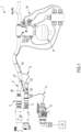
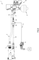
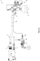
- control line 3 consists of a hose of the flexible type.
- control line 3 connects the braking system of the towing vehicle to the braking system of the trailer, thus synchronizing the braking thereof.
- the actuation of the braking system of the vehicle causes the actuation of the braking system of the trailer.
- the device 1 comprises at least a second female joint 5 communicating with an additional line 6 adapted to control the automatic and/or parking brake of the trailer and intended to receive a second male joint 7 of a towing vehicle connectable to a source of a work fluid at a second pressure.
- connection of the second female joint 5 to the second male joint 7 connects the additional line 6 to the parking brake of the towing vehicle.
- the second pressure of the additional line 6 is controlled by the parking brake of the towing vehicle.
- the parking brake of the towing vehicle is applied and released to depressurize and pressurize the additional line 6 respectively, which, in this way, communicates the status of the towing vehicle to the trailer.
- the additional line 6 is adapted to apply the automatic and/or parking brake of the trailer in the event of an emergency, i.e., when the trailer disengages from the towing vehicle.
- the device 1 comprises at least one primary braking line 8a connectable to the braking system of the trailer.
- the primary braking line 8a is adapted to supply the braking system of the trailer with the work fluid required for its operation in synchrony with the braking system of the towing vehicle.
- the secondary braking line 8b is adapted to supply the automatic and/or parking brake of the trailer with the fluid required for its operation substantially to keep the trailer braked.
- the accumulator 9 is adapted to store within it an amount of work fluid which can be used to intervene in the operation of the automatic and/or parking brake of the trailer.
- the accumulator 9 is adapted to store within it enough work fluid to apply the automatic and/or parking brake of the trailer, i.e., to prevent the trailer from moving, e.g. in the event of an emergency.
- the device 1 comprises valve means 10 placed between the accumulator 9 and the secondary braking line 8b and movable between at least one supply position, wherein the accumulator 9 is placed in communication with the secondary braking line 8b, and at least one isolation position, wherein the accumulator 9 is isolated from the secondary braking line 8b.
- valve means 10 comprise a pair of solenoid valves 51, 52 which allow the movement between the supply position and the isolation position.
- the valve means 10 are mounted on the trailer.
- the accumulator 9 supplies the secondary braking line 8b with the work fluid required to apply the automatic and/or parking brake of the trailer, preventing the movement thereof.
- valve means 10 are moved to the supply position in the absence of power supply and/or of electric/electronic connection, as described later in this disclosure.
- valve means 10 are moved to the isolation position as a result of the performance of one or more start-up operations, as described later in this disclosure with reference to the method of using the device 1.
- the device 1 comprises at least one power line 11 connected to the second female joint 5 and provided with an electrical connector 12 adapted to be coupled to a corresponding electrical connector of the towing vehicle.
- the power line 11 is connected to the additional line 6.
- the electrical connector of the towing vehicle is connected to the electric/electronic system of the vehicle itself, e.g. to communicate with an electric/electronic control unit.
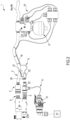
- the device 1 comprises at least a first portion 22 connected to the second female joint 5 and connectable to the second male joint 7 of the towing vehicle, and at least a second portion 23 coupled, in use, to the first portion 22 in a removable manner.
- the device 1 comprises joining means 53 placed between the second female joint 5 and the first portion 22, connecting them together in a fluid-operated manner.
- the joining means 53 define a tubular body.
- the joining means 53 are of the flexible type.
- the joining means 53 may be of the rigid type.
- the power line 11 is connected to the first portion 22.
- the power line 11 comprises one or more linking lines 17a, e.g., of the type of electrical cables, placed between the second female joint 5 and the electrical connector 12.
- the device 1 comprises sensing means 15 of the second pressure arranged along the additional line 6.
- valve means 10 remain in the supply position (and the trailer remains braked) if the work fluid within the accumulator 9 does not reach a pressure greater than or equal to the switching value.
- the additional line 6 is of the electric/electronic type and is electrically connected to the sensing means 15.
- the electrical connector 12 and the first portion 22 define a single rigid body piece.
- the switch of the switching component 25 causes the closure and opening of an emergency warning circuit of the trailer, not shown in the figures, defined by at least two linking lines 17a.
- the switching component 25 is configured to switch and close the warning circuit on the first portion 22.
- the power line 11 transmits the electric/electronic warning signal of the trailer's emergency.
- such an electric/electronic warning signal is transmitted to the electrical connector 12 to warn the user of the device, preferably on the towing vehicle, of an emergency.
- the electric/electronic warning signal transmitted to the connector 12 causes the actuation of a warning device, such as a warning light 21, of the towing vehicle.
- the device 1 comprises temporary fastening means 26 for temporarily fastening the second portion 23 to the first portion 22 movable between an engagement position, wherein the second portion 23 is fastened to the first portion 22, and a disengagement position, wherein the second portion 23 is released from the first portion 22.
- the fastening means 26 are mechanically connected to the control line 3 and are movable from the engagement position to the disengagement position as a result of the tensioning and subsequent disconnection of the control line 3.
- the system 1 may comprise automatic disconnection means of the joints 2, 4 adapted to unfasten the latter upon exceeding a threshold tensile force (exerted on the joints 2, 4 as a result of the tensioning of the control line 3).
- the automatic disconnection means are made on at least one of the joints 2, 4, preferably on the first female joint 2.
- the fastening means 26 are connected to the control line 3 by interposition of a connecting element 27, preferably of the flexible type, such as e.g. a cable or the like.
- the fastening means 26 are of the interlocking type, placed between the first portion 22 and the second portion 23, and are displaced from the engagement position to the disengagement position as a result of the tensioning of the connecting means 16 alone.
- valve means 10 are moved between the supply position (wherein the trailer is braked) and the isolation position (wherein the trailer is free to be towed) depending on the switch of the switching elements 28, 29.
- valve means 10 are moved from the supply position to the isolation position when both switching elements are switched.
- the first switching element 28 switches when it receives the electric/electronic command signal and when the first pressure value is greater than or equal to the reference value.
- the first switching element 28 switches when there is enough pressure within the control line 3 and when it receives the electric/electronic command signal, preferably a command signal transmitted as a result of the ignition of the towing vehicle. Preferably, once switched, the first switching element 28 remains switched until it receives the electric/electronic command signal.
- the second switching element 29 switches when the first switching element 28 is switched and when there is enough pressure within the accumulator 9. Preferably, once switched, the second switching element 29 remains switched until the first switching element 29 remains switched.
- the switching elements 28, 29 are of the type of relay or the like.
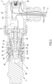
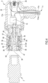
- valve assembly 32 comprises:
- the passageway 44 communicates with the joining means 53 in a fluid-operated manner.
- the fixed body 36 comprises a first stretch 37 provided with first sealing means 46 and a second stretch 38 provided with second sealing means 47.
- passage opening 39 is placed between the first sealing means 46 and the second sealing means 47.
- valve element 34 is tightly associated with the first sealing means 46 and with the second sealing means 47 in the closed position and is disengaged from the second sealing means 47 in the open position, thus allowing the passage of the work fluid through the passage opening 39.
- valve element 34 in its displacement from the open position to the closed position, performs a stroke stretch in engagement with the second sealing means 47.
- valve element 34 in the closed position between the first sealing means 46 and the second sealing means 47 an expandable chamber 40 is defined. Specifically, the valve element 34 varies the volume of the expandable chamber 40 during the stroke stretch.
- the second female joint 5 comprises at least one elastic element 35 operating in conjunction with the valve element 34.
- the elastic element 35 is elastically charged as a result of the transition from the closed position to the open position.
- the elastic element 35 tends to elastically counteract the movement of the valve element 34 from the closed position to the open position.
- the elastic element 35 naturally tends to move and to keep the valve element in the closed position.
- the first stretch 37 has a first diameter and the second stretch 38 has a second diameter.
- valve element 34 has a first segment 49 associated with the first sealing means 46 in a sliding manner and a second segment 50 associable with the second sealing means 47 in a sliding manner, wherein the first segment 49 has a larger diameter than the second segment 50.
- the second sealing means 47 may be of the one-way type, so as to relieve any overpressures operating within the expandable chamber 40.
- the present invention relates to a method of using a device 1 for controlling the braking of a trailer, comprising:
- the phase of releasing the parking and/or automatic brake comprises at least one step of pressurization of the additional line 6 until the switching value is achieved.
- phase of pressurization of the additional line 6 is carried out by releasing the parking brake of the towing vehicle.
- phase of releasing the parking and/or automatic brake comprises at least one pressurization of the control line 3 until the reference value is achieved.
- step of pressurization of the control line 3 is carried out by the application of the service brake of the towing vehicle.
- phase of pressurization of the accumulator 9 is carried out by the application of the service brake of the towing vehicle.
- step of pressurization of the additional line 6 is carried out prior to the step of pressurization of the control line 3.
- the step of pressurization of the additional line 6 is carried out prior to the first application of the service brake of the towing vehicle which is required to release the automatic braking of the trailer.
- the connecting means, the power line and the sensing means allow the functionality of the device to be expanded compared to the devices of known type.
- the connecting means, the power line and the sensing means make it easier to use the device compared to the devices of known type.
Landscapes
- Engineering & Computer Science (AREA)
- Transportation (AREA)
- Mechanical Engineering (AREA)
- Physics & Mathematics (AREA)
- Fluid Mechanics (AREA)
- Valves And Accessory Devices For Braking Systems (AREA)
- Regulating Braking Force (AREA)
Applications Claiming Priority (1)
| Application Number | Priority Date | Filing Date | Title |
|---|---|---|---|
| IT102023000027057A IT202300027057A1 (it) | 2023-12-18 | 2023-12-18 | Dispositivo per il controllo della frenatura di un rimorchio |
Publications (1)
| Publication Number | Publication Date |
|---|---|
| EP4574592A1 true EP4574592A1 (fr) | 2025-06-25 |
Family
ID=89983572
Family Applications (1)
| Application Number | Title | Priority Date | Filing Date |
|---|---|---|---|
| EP24220999.7A Pending EP4574592A1 (fr) | 2023-12-18 | 2024-12-18 | Dispositif de commande du freinage d'une remorque |
Country Status (2)
| Country | Link |
|---|---|
| EP (1) | EP4574592A1 (fr) |
| IT (1) | IT202300027057A1 (fr) |
Citations (5)
| Publication number | Priority date | Publication date | Assignee | Title |
|---|---|---|---|---|
| US5549362A (en) * | 1992-09-03 | 1996-08-27 | Grau Limited | Braking systems |
| EP0829406B1 (fr) * | 1996-09-14 | 2002-06-19 | WABCO GmbH & Co. OHG | Installation de frein à deux conduites pour remorque |
| WO2007123490A1 (fr) * | 2006-04-26 | 2007-11-01 | Be At Technology Pte Ltd | Dispositif de verrouillage pour remorque |
| GB2497131A (en) * | 2011-12-02 | 2013-06-05 | Knorr Bremse Systeme | Trailer having a hill hold function |
| EP3744590B1 (fr) * | 2019-05-28 | 2023-03-29 | Horsch Maschinen GmbH | Système de freinage pour une remorque insérable agricole ainsi qu'ensemble de traction agricole, comprenant un engin de traction et au moins une remorque couplée audit engin de traction |
-
2023
- 2023-12-18 IT IT102023000027057A patent/IT202300027057A1/it unknown
-
2024
- 2024-12-18 EP EP24220999.7A patent/EP4574592A1/fr active Pending
Patent Citations (5)
| Publication number | Priority date | Publication date | Assignee | Title |
|---|---|---|---|---|
| US5549362A (en) * | 1992-09-03 | 1996-08-27 | Grau Limited | Braking systems |
| EP0829406B1 (fr) * | 1996-09-14 | 2002-06-19 | WABCO GmbH & Co. OHG | Installation de frein à deux conduites pour remorque |
| WO2007123490A1 (fr) * | 2006-04-26 | 2007-11-01 | Be At Technology Pte Ltd | Dispositif de verrouillage pour remorque |
| GB2497131A (en) * | 2011-12-02 | 2013-06-05 | Knorr Bremse Systeme | Trailer having a hill hold function |
| EP3744590B1 (fr) * | 2019-05-28 | 2023-03-29 | Horsch Maschinen GmbH | Système de freinage pour une remorque insérable agricole ainsi qu'ensemble de traction agricole, comprenant un engin de traction et au moins une remorque couplée audit engin de traction |
Also Published As
| Publication number | Publication date |
|---|---|
| IT202300027057A1 (it) | 2025-06-18 |
Similar Documents
| Publication | Publication Date | Title |
|---|---|---|
| US20220288985A1 (en) | Vehicle coupling lines storage and control arrangement | |
| US9027949B2 (en) | Fifth wheel fluid lock safety system and method | |
| US10661622B2 (en) | Vehicle coupling lines storage and control arrangement | |
| CA3012626C (fr) | Agencement de stockage et de commande de lignes de couplage de vehicule | |
| US8382145B2 (en) | Automatic brake | |
| IE20170165A1 (en) | A trailer breakaway brake system | |
| EP4574592A1 (fr) | Dispositif de commande du freinage d'une remorque | |
| EP3000631B1 (fr) | Système de connection tracteur-remorque | |
| US5683148A (en) | Brake pipe pneumatic valve | |
| EP4480766A1 (fr) | Appareil de commande de frein de remorque | |
| EP3368385B1 (fr) | Dispositif de freinage pour remorques de machines agricoles | |
| EP4574596A1 (fr) | Dispositif de commande du freinage d'une remorque | |
| EP2952398B1 (fr) | Dispositif de soupape | |
| EP3650293B1 (fr) | Dispositif de contrôle du freinage d'une remorque | |
| EP3515764A1 (fr) | Système empêchant l'activation des freins à inertie d'une remorque en marche arrière | |
| US20250256539A1 (en) | Vehicle coupling lines storage and control arrangement | |
| EP3711982A1 (fr) | Dispositif pneumatique reliant un véhicule de remorquage à une remorque | |
| EP3165385B1 (fr) | Dispositif pour connexion entre vehicule et remorque | |
| EP3085589A1 (fr) | Dispositif de vanne | |
| SE509188C2 (sv) | Kopplingssystem och sätt att manövrera ett kopplingsdon |
Legal Events
| Date | Code | Title | Description |
|---|---|---|---|
| PUAI | Public reference made under article 153(3) epc to a published international application that has entered the european phase |
Free format text: ORIGINAL CODE: 0009012 |
|
| STAA | Information on the status of an ep patent application or granted ep patent |
Free format text: STATUS: THE APPLICATION HAS BEEN PUBLISHED |
|
| AK | Designated contracting states |
Kind code of ref document: A1 Designated state(s): AL AT BE BG CH CY CZ DE DK EE ES FI FR GB GR HR HU IE IS IT LI LT LU LV MC ME MK MT NL NO PL PT RO RS SE SI SK SM TR |
|
| STAA | Information on the status of an ep patent application or granted ep patent |
Free format text: STATUS: REQUEST FOR EXAMINATION WAS MADE |
|
| 17P | Request for examination filed |
Effective date: 20251217 |