EP4574596A1 - Vorrichtung zur steuerung der bremsung eines anhängers - Google Patents
Vorrichtung zur steuerung der bremsung eines anhängers Download PDFInfo
- Publication number
- EP4574596A1 EP4574596A1 EP24220096.2A EP24220096A EP4574596A1 EP 4574596 A1 EP4574596 A1 EP 4574596A1 EP 24220096 A EP24220096 A EP 24220096A EP 4574596 A1 EP4574596 A1 EP 4574596A1
- Authority
- EP
- European Patent Office
- Prior art keywords
- fact
- ring nut
- tubular body
- coupling element
- trailer
- Prior art date
- Legal status (The legal status is an assumption and is not a legal conclusion. Google has not performed a legal analysis and makes no representation as to the accuracy of the status listed.)
- Pending
Links
Images


Classifications
-
- B—PERFORMING OPERATIONS; TRANSPORTING
- B60—VEHICLES IN GENERAL
- B60T—VEHICLE BRAKE CONTROL SYSTEMS OR PARTS THEREOF; BRAKE CONTROL SYSTEMS OR PARTS THEREOF, IN GENERAL; ARRANGEMENT OF BRAKING ELEMENTS ON VEHICLES IN GENERAL; PORTABLE DEVICES FOR PREVENTING UNWANTED MOVEMENT OF VEHICLES; VEHICLE MODIFICATIONS TO FACILITATE COOLING OF BRAKES
- B60T17/00—Component parts, details, or accessories of power brake systems not covered by groups B60T8/00, B60T13/00 or B60T15/00, or presenting other characteristic features
- B60T17/04—Arrangements of piping, valves in the piping, e.g. cut-off valves, couplings or air hoses
- B60T17/043—Brake line couplings, air hoses and stopcocks
-
- B—PERFORMING OPERATIONS; TRANSPORTING
- B60—VEHICLES IN GENERAL
- B60T—VEHICLE BRAKE CONTROL SYSTEMS OR PARTS THEREOF; BRAKE CONTROL SYSTEMS OR PARTS THEREOF, IN GENERAL; ARRANGEMENT OF BRAKING ELEMENTS ON VEHICLES IN GENERAL; PORTABLE DEVICES FOR PREVENTING UNWANTED MOVEMENT OF VEHICLES; VEHICLE MODIFICATIONS TO FACILITATE COOLING OF BRAKES
- B60T17/00—Component parts, details, or accessories of power brake systems not covered by groups B60T8/00, B60T13/00 or B60T15/00, or presenting other characteristic features
-
- B—PERFORMING OPERATIONS; TRANSPORTING
- B60—VEHICLES IN GENERAL
- B60T—VEHICLE BRAKE CONTROL SYSTEMS OR PARTS THEREOF; BRAKE CONTROL SYSTEMS OR PARTS THEREOF, IN GENERAL; ARRANGEMENT OF BRAKING ELEMENTS ON VEHICLES IN GENERAL; PORTABLE DEVICES FOR PREVENTING UNWANTED MOVEMENT OF VEHICLES; VEHICLE MODIFICATIONS TO FACILITATE COOLING OF BRAKES
- B60T15/00—Construction arrangement, or operation of valves incorporated in power brake systems and not covered by groups B60T11/00 or B60T13/00
- B60T15/02—Application and release valves
- B60T15/18—Triple or other relay valves which allow step-wise application or release and which are actuated by brake-pipe pressure variation to connect brake cylinders or equivalent to compressed air or vacuum source or atmosphere
- B60T15/20—Triple or other relay valves which allow step-wise application or release and which are actuated by brake-pipe pressure variation to connect brake cylinders or equivalent to compressed air or vacuum source or atmosphere controlled by two fluid pressures
- B60T15/203—Trailer control valves
-
- B—PERFORMING OPERATIONS; TRANSPORTING
- B60—VEHICLES IN GENERAL
- B60T—VEHICLE BRAKE CONTROL SYSTEMS OR PARTS THEREOF; BRAKE CONTROL SYSTEMS OR PARTS THEREOF, IN GENERAL; ARRANGEMENT OF BRAKING ELEMENTS ON VEHICLES IN GENERAL; PORTABLE DEVICES FOR PREVENTING UNWANTED MOVEMENT OF VEHICLES; VEHICLE MODIFICATIONS TO FACILITATE COOLING OF BRAKES
- B60T15/00—Construction arrangement, or operation of valves incorporated in power brake systems and not covered by groups B60T11/00 or B60T13/00
- B60T15/02—Application and release valves
- B60T15/18—Triple or other relay valves which allow step-wise application or release and which are actuated by brake-pipe pressure variation to connect brake cylinders or equivalent to compressed air or vacuum source or atmosphere
- B60T15/20—Triple or other relay valves which allow step-wise application or release and which are actuated by brake-pipe pressure variation to connect brake cylinders or equivalent to compressed air or vacuum source or atmosphere controlled by two fluid pressures
- B60T15/22—Triple or other relay valves which allow step-wise application or release and which are actuated by brake-pipe pressure variation to connect brake cylinders or equivalent to compressed air or vacuum source or atmosphere controlled by two fluid pressures with one or more auxiliary valves, for braking, releasing, filling reservoirs
Definitions
- the present invention relates to a device for controlling the braking of a trailer.
- the towing vehicles are connected to their trailers by means of a connecting device which allows their respective braking systems to be set in communication with each other, so that the braking of the towing vehicle operated by the operator also causes braking of the towed trailer.
- the braking system of the trailer is therefore driven by the braking system of the tractor in order to synchronize the braking forces operating thereon.
- the connecting device between the towing vehicle and the relevant trailer comprises a pair of female joints associated with the trailer and intended to receive corresponding male joints connected to the towing vehicle.
- first female joint communicating with a control line which can be connected to the trailer's braking system and a second female joint communicating with an additional line adapted to command the parking and/or automatic brake of the trailer itself.
- control line and the additional line generally consisting of hoses adapted to carry a work fluid (e.g., pressurized oil), communicate with a valve (so-called “brake valve on the trailer") adapted to adjust the outflow of the work fluid towards the braking line and towards the automatic and/or parking brake.
- a work fluid e.g., pressurized oil
- the main aim of the present invention is to devise a device for braking trailers which allows preventing at least one of the lines connecting the female joints to the trailer-brake valve from breaking as a result of excessive and unwanted movement of the trailer away from the towing vehicle.
- one object of the present invention is to prevent oil spillage on the ground as a result of unwanted detachment of the fluid-operated lines connecting the female joints to the trailer-brake valve.
- Another object of the present invention is to minimize the time required to restore the functionality of the trailer's braking system as a result of an unwanted detachment of the trailer from the towing vehicle.
- Another object of the present invention is to devise a device for controlling the braking of a trailer which allows the drawbacks of the prior art to be overcome in compliance with the relevant European regulations.
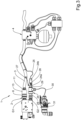
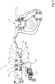
- reference numeral 1 globally denotes a device for controlling the braking of a trailer.
- the device 1 comprises a first female joint 2 associated with a trailer and a control line 3 associated with the first female joint 2 and connectable to the braking system of the trailer itself.
- the first female joint 2 is intended to receive a first male joint G1 associated with the towing vehicle and connectable to one source of a work fluid, e.g., oil, at a first pressure.
- a work fluid e.g., oil
- the control line 3 is set in communication with the trailer's braking system via a trailer-brake valve 4.
- control line 3 consists of a hose of the flexible type.
- the first female joint 2 comprises a tubular body 5 defining a passage channel 6 of a work fluid and valve means 7 housed within the tubular body 5 and movable between an open position and a closed position to allow and prevent, respectively, the outflow of the work fluid through the passage channel itself.
- the device 1 then comprises a ring nut 8 associated with the tubular body 5 in a sliding manner and movable between a securing position, wherein it prevents the first male joint from being inserted/extracted, and a release position, wherein it allows the first male joint to be inserted/extracted.
- the tubular body 5 has, at its end portion facing, in use, the first male joint G1, a plurality of radially-arranged through seats 9 and within which the balls 10 are housed.
- the balls 10 protrude within the tubular body 5 thus preventing the first male joint G1 from being inserted or, if the latter was already inserted, from being extracted.
- the ring nut 8 has recesses 18 which are arranged, in the release position, substantially aligned with the seats 9, thus allowing the balls 10 to be raised and the first male joint G1 to be inserted/extracted.
- the first female joint 2 comprises at least one coupling element 11 associated with the tubular body 5 in a sliding manner and defining a transfer channel 12 of the work fluid communicating with the passage channel 6 downstream of the valve means 7, where the coupling element 11 is connected to the control line 3.
- the coupling element 11 is mechanically connected to the ring nut 8 and is movable between a home configuration, wherein the ring nut 8 is free to move between the securing position and the release position, and an emergency configuration, wherein it drags the ring nut 8 to the release position as a result of the force exerted thereon by the control line 3.
- the device 1 comprises a guiding element 13 fitted externally on the tubular body 5 and locked together with the coupling element 11, where the guiding element 13 interacts with the ring nut 8 to drag it towards the release position as a result of the displacement of the coupling element 11 towards the emergency configuration.
- the guiding element 13 has an abutment surface 13a which interacts, when the coupling element 11 is in the home position and the ring nut 8 is in the securing position, with a first stop surface 8a defined by the ring nut 8.
- the abutment surface 13a interacts with the first stop surface 8a by interposition of an O-ring 14.
- the device 1 comprises first elastic means 15, of the type of a coil spring, adapted to counteract the displacement of the ring nut 8 towards the release position and second elastic means 16 adapted to counteract the displacement of the guiding element 13 towards the emergency position.
- the first elastic means 15 are positioned between the ring nut 8 and the tubular body 5 and the second elastic means 16 are positioned between the guiding element 13 and a fixed abutment body 17.
- the second elastic means 16 are of the type of a coil spring having one end resting on the guiding element 13 and the opposite end resting on the abutment body 17, integral with the tubular body 5.
- the ring nut 8 also has a second stop surface 8b adapted to interact with the tubular body 5 in its displacement towards the securing position.
- the first stop surface 8a and the second stop surface 8b define the end-of-stroke positions of the ring nut 8.
- the guiding element 13 has a first resting surface 13b adapted to interact, in its displacement towards the home configuration, with a first fixed counter-stop surface 19 and a second resting surface 13c adapted to interact, in its displacement towards the emergency configuration, with a second fixed counter-stop surface 20.
- the resting surfaces 13b, 13c then define the end-of-stroke position of the guiding element 13.
- valve means 7 comprise a movable element 7a supporting a gasket 7b and movable between the closed position and the open position counteracting further elastic means 7c.
- the first female joint 2 comprises one abutment element 21 associated integral with the tubular element 5 and adapted to interact on one side with the gasket 7b, in the closed position of the movable element 7a, and on the other side with the first male joint G1.
- the movable element 7a is pushed to the open position thus allowing the passage of the work fluid within the passage channel 6.
- the coupling element 11 is associated with the tubular element 5 in a sliding and sealed manner, between the coupling element 11 and the tubular element 5 being defined an inner chamber 22 isolated by sealing from the passage channel 6 and communicating with the outside.
- the connection of the inner chamber 22 with the outside enables the proper displacement of the coupling element 11 even in the presence of minimal hydraulic leakage from the sealing elements, thus ensuring that its movement is subject only to the force exerted by the control line 3.
- the second elastic means 16 are housed within an annular chamber 23 positioned between the guiding element 13 and the tubular body 5 and communicating with the inner chamber 22 via a meatus 29, where such annular chamber 23 is set in communication with the external environment.
- the coupling element 11 has no thrust surfaces on which the work fluid operates, so it is not subject to any axial force. Therefore, the coupling element is insensitive to the inner pressure of the work fluid and its displacement subject only to the force exerted by the second elastic means 16.
- the device 1 also comprises, then, a second female joint 24 communicating with an additional line 25 adapted to control the automatic and/or parking brake of the trailer and intended to receive a second male joint G2 of the towing vehicle connectable to a source of a work fluid at a second pressure.
- the additional line 25 is set in communication with the automatic and/or parking brake of the trailer via the trailer-brake valve 4. More specifically, when the pressure of the work fluid coming from the second male joint G2 exceeds a predefined value, generally of between 15 bar and 35 bar, the additional line 25 commands the switching of the trailer-brake valve 4 so as to supply the automatic and/or parking brake in a fluid-operated manner, thus releasing it. Conversely, as long as the pressure of the work fluid remains below the predefined value, the automatic and/or parking brake remains activated.
- the second female joint 24 comprises a first portion 24a connectable to the second male joint G2 and a second portion 24b associated with the first portion 24a in a removable manner and communicating with the additional line 25.
- the second female joint 24 comprises temporary fastening means 26 for temporarily fastening the second portion 24b to the first portion 24a movable between an engagement position, wherein the second portion 24b is fastened to the first portion 24a, and a disengagement position, wherein the second portion 24b is released from the first portion 24a. In the disengagement position, therefore, the second portion 24b is separable from the first portion 24a, while, in the engagement position, the second portion 24b is bound to the first portion 24a.
- the fastening means 26 are mechanically connected to the control line 3 and are movable from the engagement position to the disengagement position as a result of the tensioning of the control line itself.
- the additional line 25 is mechanically connected to the control line 3 and the fastening means 26 are displaced from the engagement position to the disengagement position before the additional line 25 is put into tension as a result of the tensioning of the control line 3.
- the additional line 25 is of the flexible type (e.g., consisting of a multi-core electrical cable) and constrained to the control line 3 so that it is put into tension as a result of a linear displacement of a predefined magnitude of the control line itself, and the fastening means 26 are connected to the control line 3 by means of a linking element 27, of an inextensible type, having shorter length than said linear displacement of a predefined magnitude.
- the linking element 27 controls the displacement of the fastening means 26 from the engagement position to the disengagement position before the additional line 25 is put into tension, thus preventing it from breaking.
- the first portion 24a defines an additional channel 28 for the passage of the work fluid to the second pressure and pressure sensing means 29 along the additional channel 28.
- the sensing means 29 e.g. of the type of a pressure transducer or a pressure switch, are adapted to send an electrical signal when the pressure of the work fluid along the additional channel 28 achieves a predefined value.
- the additional line 25 is of the electrical type and is electrically connected to the sensing means 29.
- the second portion 24b comprises electrical connection means of the additional line 25 to the sensing means 29, so the electrical connection between the additional line 25 and the sensing means 29 is interrupted as a result of the detachment of the second portion 24b from the first portion 24a.
- the device 1 comprises at least one electrical line 30 connected to the second female joint 24 and provided with an electrical connector 31 adapted to be coupled to a corresponding electrical connector of the towing vehicle.
- the electrical line 30 is configured to exchange at least one electrical signal with the valve means 7 via the additional electrical line 25.
- the additional line 25 electrically connects the valve means 7 to the sensing means 29 and to the electrical line 30.
- the ring nut 8 As known to the technician in the field, in order to carry out the insertion of the first male joint G1 within the first female joint 2, it is first necessary to bring the ring nut 8 to the release position, wherein the balls 10 are pushed inside the relevant recesses 18 as a result of the insertion of the first male joint itself. Once the first male joint G1 has been introduced into the first female joint 2, the ring nut 8 is returned to the securing position so that the balls 10, entering the respective grooves defined on the first male joint G1, prevent them from coming out.
- valve means 7 are pushed to the open position so as to allow the work fluid to flow out through the passage channel 6 and therefrom along the control line 3 passing through the coupling element 11.
- the coupling element 11 remains in the home configuration.
- the coupling element 11 receives a direct force away from the tubular body 5 and thus moves with respect thereto.
- the coupling element 11 shifts with respect to the tubular body 5, dragging the guiding element 13 with it (provided that the force exerted is sufficient to overcome the force of the second elastic means 16) and displacing from the home configuration to the emergency configuration.
- the linking element 27 causes the fastening means 26 to displace from the engagement position to the disengagement position, thus allowing the separation of the second portion 24b, which then follows the trailer, from the first portion 24a, which instead remains connected to the towing vehicle.
- Such a separation results in the electrical disconnection between the additional line 25 and the sensing means 29 and the consequent activation of the automatic and/or parking brake.
- the described invention achieves the intended objects and the fact is particularly emphasized that the device covered by the present invention makes it possible to prevent the components connecting the trailer to the towing vehicle from being broken, and in particular of the hoses traversed by the work fluid, as a result of an unwanted away movement of the trailer itself.
- the transformation of the pressure signal coming from the second male joint into an electrical signal that is transmitted from the additional line to the trailer-brake valve makes it possible to limit the risk of oil leakage in the event of a break and to simplify the constructive embodiment of the device.
Landscapes
- Engineering & Computer Science (AREA)
- Transportation (AREA)
- Mechanical Engineering (AREA)
- Quick-Acting Or Multi-Walled Pipe Joints (AREA)
- Valves And Accessory Devices For Braking Systems (AREA)
Applications Claiming Priority (1)
| Application Number | Priority Date | Filing Date | Title |
|---|---|---|---|
| IT102023000027060A IT202300027060A1 (it) | 2023-12-18 | 2023-12-18 | Dispositivo per il controllo della frenatura di un rimorchio |
Publications (1)
| Publication Number | Publication Date |
|---|---|
| EP4574596A1 true EP4574596A1 (de) | 2025-06-25 |
Family
ID=89983350
Family Applications (1)
| Application Number | Title | Priority Date | Filing Date |
|---|---|---|---|
| EP24220096.2A Pending EP4574596A1 (de) | 2023-12-18 | 2024-12-16 | Vorrichtung zur steuerung der bremsung eines anhängers |
Country Status (2)
| Country | Link |
|---|---|
| EP (1) | EP4574596A1 (de) |
| IT (1) | IT202300027060A1 (de) |
Citations (5)
| Publication number | Priority date | Publication date | Assignee | Title |
|---|---|---|---|---|
| DE1655089A1 (de) * | 1966-10-05 | 1971-10-21 | Tracteurs F A R Soc D | Druckluft- bzw. Vakuum-Bremsvorrichtung fuer Kraftfahrzeuge mit Anhaenger |
| EP2955073A1 (de) * | 2014-05-30 | 2015-12-16 | Studio Tecnico 6 M S.R.L. | Anordnung zur Verbindung Zugfahrzeug-Anhängerfahrzeug |
| EP3085590A1 (de) * | 2014-11-11 | 2016-10-26 | Studio Tecnico 6 M S.R.L. | Vorrichtung zur steuerung des bremssystems eines anhängerfahrzeugs |
| EP3000631B1 (de) * | 2014-05-30 | 2018-08-08 | SAFIM S.p.A. | Verbindungssystem für zugfahrzeug-anhänger |
| EP3611063B1 (de) * | 2018-07-26 | 2021-03-17 | SAFIM S.p.A. | Zugfahrzeug-anhänger-verbindungsanordnung |
-
2023
- 2023-12-18 IT IT102023000027060A patent/IT202300027060A1/it unknown
-
2024
- 2024-12-16 EP EP24220096.2A patent/EP4574596A1/de active Pending
Patent Citations (5)
| Publication number | Priority date | Publication date | Assignee | Title |
|---|---|---|---|---|
| DE1655089A1 (de) * | 1966-10-05 | 1971-10-21 | Tracteurs F A R Soc D | Druckluft- bzw. Vakuum-Bremsvorrichtung fuer Kraftfahrzeuge mit Anhaenger |
| EP2955073A1 (de) * | 2014-05-30 | 2015-12-16 | Studio Tecnico 6 M S.R.L. | Anordnung zur Verbindung Zugfahrzeug-Anhängerfahrzeug |
| EP3000631B1 (de) * | 2014-05-30 | 2018-08-08 | SAFIM S.p.A. | Verbindungssystem für zugfahrzeug-anhänger |
| EP3085590A1 (de) * | 2014-11-11 | 2016-10-26 | Studio Tecnico 6 M S.R.L. | Vorrichtung zur steuerung des bremssystems eines anhängerfahrzeugs |
| EP3611063B1 (de) * | 2018-07-26 | 2021-03-17 | SAFIM S.p.A. | Zugfahrzeug-anhänger-verbindungsanordnung |
Also Published As
| Publication number | Publication date |
|---|---|
| IT202300027060A1 (it) | 2025-06-18 |
Similar Documents
| Publication | Publication Date | Title |
|---|---|---|
| US5199732A (en) | Apparatus for unlocking a bogie on a tractor-trailer rig | |
| EP2318242B1 (de) | Bremssteuersystem für eine kombination aus ziehendem fahrzeug und anhängerfahrzeug | |
| EP3436290A1 (de) | Aufbewahrungs- und steueranordnung für fahrzeugkopplungsleitungen | |
| US20240375627A1 (en) | Electropneumatic trailer parking-brake system, trailer, towing combination | |
| EP4574596A1 (de) | Vorrichtung zur steuerung der bremsung eines anhängers | |
| EP3000631B1 (de) | Verbindungssystem für zugfahrzeug-anhänger | |
| EP3225473B1 (de) | Vorrichtung zur anhängerbremssteuerung | |
| EP2952398B1 (de) | Ventilvorrichtung | |
| EP4480766A1 (de) | Anhängerbremssteuergerät | |
| EP3650293B1 (de) | Vorrichtung zur steuerung der bremsung eines anhängers | |
| EP3800097B1 (de) | Verfahren, schaltung, verteiler und bremsanlage für gezogene fahrzeuge | |
| EP3401176B1 (de) | Gerät zum kontrollieren der bremsen eines anhängers | |
| EP2955073B1 (de) | Anordnung zur Verbindung Zugfahrzeug-Anhängerfahrzeug | |
| EP3368385B1 (de) | Bremsvorrichtung für anhänger von landwirtschaftlichen maschinen | |
| EP4574592A1 (de) | Vorrichtung zur steuerung der bremsen eines anhängers | |
| EP3611063B1 (de) | Zugfahrzeug-anhänger-verbindungsanordnung | |
| EP3711982B1 (de) | Pneumatisches gerät zum verbinden eines schleppfahrzeugs mit einem anhänger | |
| US20070296267A1 (en) | Apparatus for braking systems of articulated vehicles | |
| EP3165385B1 (de) | Vorrichtung für eine verbindung zwischen fahrzeug und anhänger | |
| EP3243715B1 (de) | Hydraulischer verteiler zum bremsen eines geräteanhängers | |
| EP3319848B1 (de) | Betätigungsvorrichtung eines ventils zum bremsen eines anhängers | |
| EP3401175B1 (de) | Gerät zur steuerung der bremse eines anhängers | |
| EP3085589B1 (de) | Ventilanordnung | |
| EP1137565B1 (de) | Anhängerbremsventil | |
| EP1149008A1 (de) | Sicherheitsvorrichtung- und anlage zur verbesserung einer sicherheitsbremsanlage für traktoren mit anhänger |
Legal Events
| Date | Code | Title | Description |
|---|---|---|---|
| PUAI | Public reference made under article 153(3) epc to a published international application that has entered the european phase |
Free format text: ORIGINAL CODE: 0009012 |
|
| STAA | Information on the status of an ep patent application or granted ep patent |
Free format text: STATUS: THE APPLICATION HAS BEEN PUBLISHED |
|
| AK | Designated contracting states |
Kind code of ref document: A1 Designated state(s): AL AT BE BG CH CY CZ DE DK EE ES FI FR GB GR HR HU IE IS IT LI LT LU LV MC ME MK MT NL NO PL PT RO RS SE SI SK SM TR |
|
| STAA | Information on the status of an ep patent application or granted ep patent |
Free format text: STATUS: REQUEST FOR EXAMINATION WAS MADE |
|
| 17P | Request for examination filed |
Effective date: 20251217 |