EP4575111A1 - Dispositif d'actionnement pour déclencher une chasse d'eau d'un article sanitaire - Google Patents
Dispositif d'actionnement pour déclencher une chasse d'eau d'un article sanitaire Download PDFInfo
- Publication number
- EP4575111A1 EP4575111A1 EP23219249.2A EP23219249A EP4575111A1 EP 4575111 A1 EP4575111 A1 EP 4575111A1 EP 23219249 A EP23219249 A EP 23219249A EP 4575111 A1 EP4575111 A1 EP 4575111A1
- Authority
- EP
- European Patent Office
- Prior art keywords
- pin
- receptacle
- actuating device
- actuating
- bearing frame
- Prior art date
- Legal status (The legal status is an assumption and is not a legal conclusion. Google has not performed a legal analysis and makes no representation as to the accuracy of the status listed.)
- Pending
Links
Images


Classifications
-
- E—FIXED CONSTRUCTIONS
- E03—WATER SUPPLY; SEWERAGE
- E03D—WATER-CLOSETS OR URINALS WITH FLUSHING DEVICES; FLUSHING VALVES THEREFOR
- E03D5/00—Special constructions of flushing devices, e.g. closed flushing system
- E03D5/02—Special constructions of flushing devices, e.g. closed flushing system operated mechanically or hydraulically (or pneumatically) also details such as push buttons, levers and pull-card therefor
- E03D5/028—Pusher plates and actuating mechanisms for built-in cisterns
-
- E—FIXED CONSTRUCTIONS
- E03—WATER SUPPLY; SEWERAGE
- E03D—WATER-CLOSETS OR URINALS WITH FLUSHING DEVICES; FLUSHING VALVES THEREFOR
- E03D5/00—Special constructions of flushing devices, e.g. closed flushing system
- E03D5/02—Special constructions of flushing devices, e.g. closed flushing system operated mechanically or hydraulically (or pneumatically) also details such as push buttons, levers and pull-card therefor
- E03D5/09—Special constructions of flushing devices, e.g. closed flushing system operated mechanically or hydraulically (or pneumatically) also details such as push buttons, levers and pull-card therefor directly by the hand
Definitions
- the present invention relates to an actuating device for triggering a flush of a sanitary article according to claim 1.
- Actuating devices for triggering the flush of a sanitary article, such as a toilet or urinal, have become known from the state of the art.
- EP2388380 discloses such an actuating device as an example.
- the actuating device disclosed here comprises an actuating plate with at least one button for activating the flush.
- a support frame is arranged in front of a wall opening, and the actuator plate is connected to this support frame.
- the support frame is supported on a wall surface of a wall panel, and the actuator plate covers the support frame.
- the present invention is based on the object of providing an actuating device with an actuating plate and a bearing frame, which provides a good and permanent connection between the actuating plate and the bearing frame. This is particularly true under the condition of simple assembly of the actuating plate on the bearing frame.
- the actuating device serves to trigger a flush of a sanitary article.
- the actuating device comprises an actuating plate, which has at least one actuating element, and a bearing frame.
- the actuating plate and the Bearing frames can be connected to one another via a fastening structure.
- the fastening structure has at least a first fastening point and a second fastening point.
- the first fastening point has a first receptacle and a first pin engaging in the first receptacle.
- the first receptacle and the first pin are designed such that the first pin is guided in the first receptacle without locking.
- the second fastening point has a second receptacle and a second pin engaging in the second receptacle.
- the second receptacle and the second pin are designed such that the second pin is firmly locked in the second receptacle with respect to a movement transverse to the pin axis of the second pin.
- This type of bearing has the advantage that during installation, the first pin can be positioned in the area of the first receptacle, and that as the actuator plate moves progressively toward the bearing frame, the actuator plate performs a pivoting movement around the pin that slides into the first receptacle.
- This type of bearing also has the advantage that both bearing pins can be brought into contact with their respective receptacles simultaneously, resulting in a kind of parallel movement between the bearing plate and the actuator plate. This provides the installer with several installation options.
- the actuating element is preferably an actuating button movably mounted in the actuating plate.
- the actuating element can also be an electronic sensor, such as an infrared sensor.
- the actuating element is arranged so as to be movable, in particular pivotable, relative to the actuating plate.
- the actuating element is connected to the actuating plate via a hinge.
- the bearing frame is preferably connected to a cistern or parts of a cistern.
- the tenon axis extends centrally through the respective tenon.
- the first receptacle is designed such that the first pin can be pivoted about the pin axis of the first pin.
- said receptacles are arranged on the actuating plate, and said pins are arranged on the bearing frame.
- said pins are arranged on the actuating plate, and said receptacles are arranged on the bearing frame.
- the shape of the first receptacle is different from the shape of the second receptacle. This prevents, for example, the first pin from sliding past the first receptacle when the second pin engages in the second receptacle when the actuator plate is mounted on the bearing frame.
- the secure sliding or locking of the pins in the receptacles ensures secure attachment of the actuator plate to the bearing frame.
- the first pin and the second pin are substantially identical or identical to one another.
- the pins may also be differently configured.
- the first pin and/or the second pin have a cylindrical portion and a recessed portion.
- the cylindrical portion extends partially around a pin axis, and the recessed portion provides a recess in the respective pin.
- This design allows the cross-section of the pin to be made smaller, thus saving material. Furthermore, the pin can be designed to be more stable against deformation under force compared to pins with a smaller diameter.
- the recess section extends as a recess from the outside into the cylinder, such that the lateral surface of the cylinder section extends only partially around the central axis.
- the fit between the first receptacle and the first pin is designed as a clearance fit.
- the fit between the first The recess and the first pin are designed as a clearance fit, at least in the vertical direction.
- the vertical direction is the direction that runs vertically in the installed position, i.e., in the perpendicular direction.
- the clearance fit is a fit with a clearance of maximum 0.2 millimeters, in particular maximum 0.1 millimeters.
- a first guide section is assigned to the first receptacle, wherein the first pin can be moved through the guide section via an assembly movement in a direction transverse to its pin axis and is inserted into the first receptacle via this movement.
- the first guide section is formed with a free passage opposite the receptacle, through which the first pin can be inserted into the first guide section.
- the free passage can have a clear width that is larger or smaller than the corresponding extension of the pin. If the clear width is smaller than the extension of the pin, a constriction is created that prevents the pin from sliding uncontrollably into the first receptacle during assembly. However, the constriction is dimensioned in such a way that it does not provide a true locking mechanism, but merely a slight resistance.
- the first guide section is designed such that the first pin can pivot in the guide section when moving through the first guide section.
- the first guide section is designed such that the first pin is guided on the top and bottom sides.
- a second guide section is associated with the second receptacle.
- At least one locking cam is arranged at the transition from the second guide section to the second receptacle, providing said locking.
- the second pin can be moved through the second guide section via an assembly movement in a direction transverse to its pin axis, and is inserted into the second receptacle via this movement.
- the second guide section has an upper guide surface and a lower guide surface.
- the lower guide surface protrudes further from the second receptacle than the upper guide surface.
- the upper guide surface protrudes further from the second receptacle than the lower guide surface. The longer design of one guide surface allows the pin to be guided over a longer distance.
- the upper guide surface and/or the lower guide surface is oriented such that when the second pin is inserted into the second receptacle, the first pin is moved into the first receptacle.
- the upper guide surface and/or the lower guide surface is oriented such that when the second pin is inserted into the second receptacle, the actuating plate is moved towards the bearing frame and from top to bottom with respect to the bearing frame.
- the bearing frame is formed with a frame recess, wherein the frame recess is laterally delimited by side walls and wherein the first pin and the second pin protrude into the frame recess away from the side walls.
- the first fastening points and the second fastening points are arranged in pairs. This means that there are two first fastening points and two second fastening points.
- the two first fastening points are located on opposite side walls of the bearing frame, and the two second fastening points are also located on opposite side walls of the bearing frame.
- the first receptacle and the second receptacle each have a stop surface, wherein when a force is applied during actuation of the at least one actuating element, the stop surface is pressed against the first pin and the second pin.
- the first receptacle is brought into contact with the first pin, wherein the actuating plate is pivoted about the pin axis of the first pin during the sliding of the first pin into the first receptacle and during the pivoting the second receptacle is brought into contact with the second pin.
- the actuator plate is moved further toward the bearing frame until the respective pins are fully seated in the respective receptacle.
- the first receptacle is brought into contact with the first pin and the second receptacle is brought into contact with the second pin, the actuating plate being moved towards the bearing frame and from top to bottom with respect to the bearing frame as the first pin slides into the first receptacle and as the second pin slides into the second receptacle.
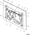
- the actuating device 1 for triggering a flush of a sanitary article according to a preferred embodiment of the present invention is shown.
- the actuating device 1 comprises an actuating plate 2 and a bearing frame 4.
- the actuating plate 2 can be connected to the bearing frame 4.
- the actuating plate 2 and the bearing frame 4 are connectable to one another via a fastening structure 5.
- the bearing frame 4 is connected to another sanitary article, such as a cistern.
- the actuating plate 2 comprises at least one actuating element 3, which here as shown in the Figure 2 As can be seen, it is mounted on the actuating plate 2 via at least one hinge 18.
- the actuating element can also be an electronic sensor.
- the fastening structure 5 has at least one first fastening point 6 and at least one second fastening point 7. Here, two first fastening points 6 and two second fastening points 7 are arranged.
- the first fastening point 6 has a first receptacle 6a and a first pin 6b engaging in the first receptacle 6a.
- the first receptacle 6a is arranged on the actuating plate 2, and the first pin 6b is arranged on the bearing frame 4.
- the first pin 6b engages in the first receptacle 6a.
- the first receptacle 6a and the first pin 6b are designed such that the first pin 6b is guided in the first receptacle 6a without locking.
- the fit between the first receptacle 6a and the first pin 6b is preferably designed as a clearance fit.
- the second fastening point 7 has a second receptacle 7a and a second pin 7b engaging in the second receptacle 7a.
- the second receptacle 7a is arranged on the actuating plate 2, and the second pin 7b is arranged on the bearing frame 4.
- the second pin 7b engages in the second receptacle 7a.
- the second receptacle 7a and the second pin 7b are designed such that the second pin 7b is firmly locked in the second receptacle 7a with respect to a movement transverse to the pin axis Z7 of the second pin 7b.
- first receptacle 6a is different from the shape of the second receptacle 7a and that the first pin 6b and the second pin 7b are essentially similar or identical to one another are trained.
- first pin 6b and the second pin 7b have a cylindrical portion 8 and a recessed portion 9 on their circumference.
- the cylindrical portion 8 extends partially around a pin axis Z6, Z7.
- the recessed portion 9 provides a recess in the respective pin 6b, 7b.
- receptacles 6a, 7a are arranged on the actuating plate 2 and the pins 6b, 7b are arranged on the bearing frame 4.
- a first guide section 10 is assigned to the first receptacle 6a. Viewed in the insertion direction of the first pin 6b, the first guide section 10 is located in front of the first receptacle 6a. This means that when the first pin 6b is inserted into the first receptacle 6a, the first pin 6b is guided by the first receptacle 6a. The first pin 6b can be moved through the guide section via an assembly movement in a direction transverse to its pin axis, and via this movement, the first pin 6b can be inserted into the first receptacle 6a.
- the first guide section 10 is designed such that the first pin 6b can pivot within the guide section 10 during movement through the guide section 10.
- the guide section 10 is designed such that the first pin 6b is guided on the top and bottom sides.
- a second guide section 12 is assigned to the second receptacle 7a. Viewed in the insertion direction of the second pin 7b, the second guide section 12 lies in front of the second receptacle 7a. This means that when the second pin 7b is inserted into the second receptacle 7a, the second pin 7b is guided into the second receptacle 7a by the guide section 12.
- the second pin 7b can be moved through the guide section via an assembly movement in a direction transverse to its pin axis, and via this movement the second pin 7b can be inserted into the second receptacle 7a.
- At least one locking cam 13 is arranged in the transition from the second guide section 12 to the second receptacle 6a. The at least one locking cam 13 ensures the aforementioned locking of the second pin 7b in the second receptacle 7a.
- the second guide section 12 here has an upper guide surface 14 and a lower guide surface 15.
- the lower guide surface 15 protrudes further from the second receptacle 7a than the upper guide surface 14, as viewed from the second receptacle 7a.
- the upper guide surface 14 protrudes further from the second receptacle 7a than the lower guide surface 15, as viewed from the second receptacle 7a.
- the upper guide surface 14 and/or the lower guide surface 15 is oriented such that when the second pin 7b is inserted into the second receptacle 7a, the first pin 6b is moved into the first receptacle 6a.
- the upper guide surface 14 and/or the lower guide surface 15 is oriented such that when the second pin 7b is inserted into the second receptacle 7a, the actuating plate 2 is moved toward the bearing frame 4 and from top to bottom with respect to the bearing frame 4.
- Both guide sections 10, 12 have a free passage 11, 19 through which the respective pin 6b, 7b slides into the respective guide section 10, 12.
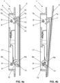
- the actuator plate 2 is shown spaced from the bearing frame 4 before the assembly process.
- the first receptacle 6a is brought into contact with the first pin 6b.
- the actuator plate 2 is thereby Figure 4b shown, oriented at an angle to the bearing frame 4.
- the actuating plate 2 is further pivoted relative to the bearing frame 4. This is shown in the Figure 4c shown.
- the first pin 6b is pivoted in the area of the first guide section 10.
- the second pin 7b slides into the second guide section 12.
- the second pin 7b comes into contact with the lower guide surface 15.
- the actuating plate 2 is moved from the position according to the Figure 4c further pivoted until the actuating plate 2 is parallel to the bearing frame 4 and the pins 6b, 7b are completely in the respective receptacle 6a, 7a, which is Figure 4d is shown.
- the first receptacle 6a is brought into contact with the first pin 6b, the actuating plate 2 being pivoted about the pin axis of the first pin 6b while the first pin 6b slides into the first receptacle 6a, and the second receptacle 7a is brought into contact with the second pin 7b during the pivoting.
- the actuating plate 2 is displaced further in the direction of the bearing frame 4 until the respective pins 6b, 7b lie completely in the respective receptacle 6a, 7a.
- the bearing frame 4 is formed with a frame recess 16.
- the frame recess 16 is laterally delimited by side walls 17.
- the first pin 6b and the second pin 7b protrude from the side walls 17 into the frame recess 16.
- first fastening points 6 and two second fastening points 7 are arranged.
- Each first fastening point 6 and each second fastening point 7 are located on the same side wall 17, and each first fastening point 6 and each second fastening point 7 are located on a side wall 17 opposite the frame recess.
- the first fastening point 6 on one side wall 17 is at the same height as the first fastening point 6 on the other side wall 17.
- the respective pin axes of the respective first pins 6b are collinear with each other.
- the first receptacle 6a and the second receptacle 7a each have a stop surface 20, wherein when a force is applied during the actuation of the at least one actuating element 3, the stop surface 20 is pressed against the first pin 6b and the second pin 7b.
- the first receptacle 6a is open on the side from which the first pin 6b protrudes, and opposite said side, a wall region 21 extends across the cross section of the first receptacle 6a.
- the second receptacle 7a is open on the side from which the second pin 7b protrudes, and opposite said side, the second receptacle 7a is also open.
Landscapes
- Engineering & Computer Science (AREA)
- Mechanical Engineering (AREA)
- Aviation & Aerospace Engineering (AREA)
- Health & Medical Sciences (AREA)
- Life Sciences & Earth Sciences (AREA)
- Hydrology & Water Resources (AREA)
- Public Health (AREA)
- Water Supply & Treatment (AREA)
- Pivots And Pivotal Connections (AREA)
Priority Applications (1)
| Application Number | Priority Date | Filing Date | Title |
|---|---|---|---|
| EP23219249.2A EP4575111A1 (fr) | 2023-12-21 | 2023-12-21 | Dispositif d'actionnement pour déclencher une chasse d'eau d'un article sanitaire |
Applications Claiming Priority (1)
| Application Number | Priority Date | Filing Date | Title |
|---|---|---|---|
| EP23219249.2A EP4575111A1 (fr) | 2023-12-21 | 2023-12-21 | Dispositif d'actionnement pour déclencher une chasse d'eau d'un article sanitaire |
Publications (1)
| Publication Number | Publication Date |
|---|---|
| EP4575111A1 true EP4575111A1 (fr) | 2025-06-25 |
Family
ID=89308064
Family Applications (1)
| Application Number | Title | Priority Date | Filing Date |
|---|---|---|---|
| EP23219249.2A Pending EP4575111A1 (fr) | 2023-12-21 | 2023-12-21 | Dispositif d'actionnement pour déclencher une chasse d'eau d'un article sanitaire |
Country Status (1)
| Country | Link |
|---|---|
| EP (1) | EP4575111A1 (fr) |
Citations (7)
| Publication number | Priority date | Publication date | Assignee | Title |
|---|---|---|---|---|
| DE8617785U1 (de) | 1986-07-03 | 1986-08-21 | Schneider, Helmhold, 5230 Altenkirchen | Betätigungsvorrichtung für einen Unterputz-Spülkasten mit Spülunterbrechung |
| DE4005753C2 (de) * | 1990-02-23 | 1995-11-02 | Duravit Ag | Wandeinbauspülkasten |
| EP0779397A1 (fr) * | 1995-12-16 | 1997-06-18 | Friatec Aktiengesellschaft Keramik- und Kunststoffwerke | Couverture |
| DE202006013859U1 (de) * | 2006-09-07 | 2006-11-02 | Mepa-Pauli Und Menden Gmbh | Steuerungsanordnung für einen Spülwasserkasten |
| EP2045405A1 (fr) * | 2007-10-03 | 2009-04-08 | Geberit Technik Ag | Plaque d'actionnement pour un dispositif d'actionnement d'un dispositif de rinçage |
| EP2388380A1 (fr) | 2010-05-20 | 2011-11-23 | Geberit International AG | Dispositif d'actionnement pour déclencher le rinçage d'un appareil sanitaire et procédé de montage d'un tel dispositif d'actionnement |
| WO2013174226A1 (fr) * | 2012-05-22 | 2013-11-28 | 李飞宇 | Panneau d'opération de drainage pour réservoir d'eau |
-
2023
- 2023-12-21 EP EP23219249.2A patent/EP4575111A1/fr active Pending
Patent Citations (7)
| Publication number | Priority date | Publication date | Assignee | Title |
|---|---|---|---|---|
| DE8617785U1 (de) | 1986-07-03 | 1986-08-21 | Schneider, Helmhold, 5230 Altenkirchen | Betätigungsvorrichtung für einen Unterputz-Spülkasten mit Spülunterbrechung |
| DE4005753C2 (de) * | 1990-02-23 | 1995-11-02 | Duravit Ag | Wandeinbauspülkasten |
| EP0779397A1 (fr) * | 1995-12-16 | 1997-06-18 | Friatec Aktiengesellschaft Keramik- und Kunststoffwerke | Couverture |
| DE202006013859U1 (de) * | 2006-09-07 | 2006-11-02 | Mepa-Pauli Und Menden Gmbh | Steuerungsanordnung für einen Spülwasserkasten |
| EP2045405A1 (fr) * | 2007-10-03 | 2009-04-08 | Geberit Technik Ag | Plaque d'actionnement pour un dispositif d'actionnement d'un dispositif de rinçage |
| EP2388380A1 (fr) | 2010-05-20 | 2011-11-23 | Geberit International AG | Dispositif d'actionnement pour déclencher le rinçage d'un appareil sanitaire et procédé de montage d'un tel dispositif d'actionnement |
| WO2013174226A1 (fr) * | 2012-05-22 | 2013-11-28 | 李飞宇 | Panneau d'opération de drainage pour réservoir d'eau |
Similar Documents
| Publication | Publication Date | Title |
|---|---|---|
| EP3606382B1 (fr) | Paroi de tiroir | |
| EP3585211B1 (fr) | Arrangement avec des pieces de fournitures et un element de connection | |
| EP3973130A1 (fr) | Ferrure pour meuble | |
| EP4180601B1 (fr) | Penture dotée d'un coulisseau de guidage allongé | |
| EP4180606A1 (fr) | Penture et porte | |
| EP3098357B1 (fr) | Dispositif d'actionnement de soupape de vidange d'un réservoir de chasse | |
| EP3564471B1 (fr) | Levier articulé pour un dispositif de déplacement d'une partie de meuble logée sur une partie d'un meuble | |
| EP0843064B1 (fr) | Ferrure pour un fenêtre | |
| DE102008043811A1 (de) | Haushaltsgerät mit Lagerzapfen mit Verdrehsicherung für Lagerbuchse | |
| EP1215357B1 (fr) | Arrangement de charnière pour portes, fenêtres ou similaires | |
| EP4575111A1 (fr) | Dispositif d'actionnement pour déclencher une chasse d'eau d'un article sanitaire | |
| EP2949842A1 (fr) | Système de poignée de porte pour un véhicule | |
| DE102016210168B3 (de) | Türantrieb für eine Kraftwagentür | |
| EP3882407A1 (fr) | Arrangement de réservoir de chasse d'eau | |
| EP4187050B1 (fr) | Dispositif de fixation pour un dispositif de fermeture de bâtiment, procédé de fabrication du dispositif de fixation ainsi que dispositif de fermeture de bâtiment | |
| EP3825481A1 (fr) | Répartiteur d'eau de chasse | |
| DE3230312A1 (de) | Locher fuer papier- und pappwaren aus im wesentlichen zweistrangpress- bzw. extrusionsprofilen | |
| EP3737262B1 (fr) | Dispositif constitué par une glissière télescopique et un entraîneur | |
| EP4146888A1 (fr) | Ensemble charnière à actionnement commun | |
| DE3215452A1 (de) | Eckumlenkung fuer treibstangenbeschlaege von fenstern, tueren od. dgl. | |
| EP4223946B1 (fr) | Système de montage pour articles sanitaires | |
| EP0258639B1 (fr) | Palier rotatif avec dispositif de freinage pour un panneau de fenêtre, porte ou similaire | |
| EP0450626B1 (fr) | Charnière en deux parties pour un battant, de préférence de meuble | |
| DE202005005121U1 (de) | Treibstangenantrieb | |
| EP4353918A1 (fr) | Dispositif d'actionnement |
Legal Events
| Date | Code | Title | Description |
|---|---|---|---|
| PUAI | Public reference made under article 153(3) epc to a published international application that has entered the european phase |
Free format text: ORIGINAL CODE: 0009012 |
|
| STAA | Information on the status of an ep patent application or granted ep patent |
Free format text: STATUS: THE APPLICATION HAS BEEN PUBLISHED |
|
| AK | Designated contracting states |
Kind code of ref document: A1 Designated state(s): AL AT BE BG CH CY CZ DE DK EE ES FI FR GB GR HR HU IE IS IT LI LT LU LV MC ME MK MT NL NO PL PT RO RS SE SI SK SM TR |
|
| STAA | Information on the status of an ep patent application or granted ep patent |
Free format text: STATUS: REQUEST FOR EXAMINATION WAS MADE |
|
| 17P | Request for examination filed |
Effective date: 20251024 |