EP4575150A1 - Unité de fermeture électrique - Google Patents
Unité de fermeture électrique Download PDFInfo
- Publication number
- EP4575150A1 EP4575150A1 EP24221066.4A EP24221066A EP4575150A1 EP 4575150 A1 EP4575150 A1 EP 4575150A1 EP 24221066 A EP24221066 A EP 24221066A EP 4575150 A1 EP4575150 A1 EP 4575150A1
- Authority
- EP
- European Patent Office
- Prior art keywords
- coupling
- spring element
- coupling member
- worm shaft
- end section
- Prior art date
- Legal status (The legal status is an assumption and is not a legal conclusion. Google has not performed a legal analysis and makes no representation as to the accuracy of the status listed.)
- Pending
Links
Images


Classifications
-
- E—FIXED CONSTRUCTIONS
- E05—LOCKS; KEYS; WINDOW OR DOOR FITTINGS; SAFES
- E05B—LOCKS; ACCESSORIES THEREFOR; HANDCUFFS
- E05B47/00—Operating or controlling locks or other fastening devices by electric or magnetic means
- E05B47/06—Controlling mechanically-operated bolts by electro-magnetically-operated detents
- E05B47/0611—Cylinder locks with electromagnetic control
- E05B47/0615—Cylinder locks with electromagnetic control operated by handles, e.g. by knobs
-
- E—FIXED CONSTRUCTIONS
- E05—LOCKS; KEYS; WINDOW OR DOOR FITTINGS; SAFES
- E05B—LOCKS; ACCESSORIES THEREFOR; HANDCUFFS
- E05B47/00—Operating or controlling locks or other fastening devices by electric or magnetic means
- E05B47/06—Controlling mechanically-operated bolts by electro-magnetically-operated detents
- E05B47/0676—Controlling mechanically-operated bolts by electro-magnetically-operated detents by disconnecting the handle
- E05B47/068—Controlling mechanically-operated bolts by electro-magnetically-operated detents by disconnecting the handle axially, i.e. with an axially disengaging coupling element
-
- E—FIXED CONSTRUCTIONS
- E05—LOCKS; KEYS; WINDOW OR DOOR FITTINGS; SAFES
- E05B—LOCKS; ACCESSORIES THEREFOR; HANDCUFFS
- E05B15/00—Other details of locks; Parts for engagement by bolts of fastening devices
- E05B15/04—Spring arrangements in locks
-
- E—FIXED CONSTRUCTIONS
- E05—LOCKS; KEYS; WINDOW OR DOOR FITTINGS; SAFES
- E05B—LOCKS; ACCESSORIES THEREFOR; HANDCUFFS
- E05B47/00—Operating or controlling locks or other fastening devices by electric or magnetic means
- E05B47/0001—Operating or controlling locks or other fastening devices by electric or magnetic means with electric actuators; Constructional features thereof
- E05B47/0012—Operating or controlling locks or other fastening devices by electric or magnetic means with electric actuators; Constructional features thereof with rotary electromotors
-
- E—FIXED CONSTRUCTIONS
- E05—LOCKS; KEYS; WINDOW OR DOOR FITTINGS; SAFES
- E05B—LOCKS; ACCESSORIES THEREFOR; HANDCUFFS
- E05B47/00—Operating or controlling locks or other fastening devices by electric or magnetic means
- E05B47/06—Controlling mechanically-operated bolts by electro-magnetically-operated detents
- E05B47/0611—Cylinder locks with electromagnetic control
- E05B47/0638—Cylinder locks with electromagnetic control by disconnecting the rotor
- E05B47/0642—Cylinder locks with electromagnetic control by disconnecting the rotor axially, i.e. with an axially disengaging coupling element
-
- E—FIXED CONSTRUCTIONS
- E05—LOCKS; KEYS; WINDOW OR DOOR FITTINGS; SAFES
- E05B—LOCKS; ACCESSORIES THEREFOR; HANDCUFFS
- E05B15/00—Other details of locks; Parts for engagement by bolts of fastening devices
- E05B15/16—Use of special materials for parts of locks
- E05B15/1614—Use of special materials for parts of locks of hard materials, to prevent drilling
-
- E—FIXED CONSTRUCTIONS
- E05—LOCKS; KEYS; WINDOW OR DOOR FITTINGS; SAFES
- E05B—LOCKS; ACCESSORIES THEREFOR; HANDCUFFS
- E05B15/00—Other details of locks; Parts for engagement by bolts of fastening devices
- E05B15/04—Spring arrangements in locks
- E05B2015/0403—Wound springs
- E05B2015/0406—Wound springs wound in a cylindrical shape
- E05B2015/0413—Wound springs wound in a cylindrical shape loaded by compression
-
- E—FIXED CONSTRUCTIONS
- E05—LOCKS; KEYS; WINDOW OR DOOR FITTINGS; SAFES
- E05B—LOCKS; ACCESSORIES THEREFOR; HANDCUFFS
- E05B15/00—Other details of locks; Parts for engagement by bolts of fastening devices
- E05B15/04—Spring arrangements in locks
- E05B2015/0437—Attachments or mountings; Mounting of springs
-
- E—FIXED CONSTRUCTIONS
- E05—LOCKS; KEYS; WINDOW OR DOOR FITTINGS; SAFES
- E05B—LOCKS; ACCESSORIES THEREFOR; HANDCUFFS
- E05B47/00—Operating or controlling locks or other fastening devices by electric or magnetic means
- E05B47/0001—Operating or controlling locks or other fastening devices by electric or magnetic means with electric actuators; Constructional features thereof
- E05B2047/0014—Constructional features of actuators or power transmissions therefor
- E05B2047/0018—Details of actuator transmissions
- E05B2047/0023—Nuts or nut-like elements moving along a driven threaded axle
-
- E—FIXED CONSTRUCTIONS
- E05—LOCKS; KEYS; WINDOW OR DOOR FITTINGS; SAFES
- E05B—LOCKS; ACCESSORIES THEREFOR; HANDCUFFS
- E05B47/00—Operating or controlling locks or other fastening devices by electric or magnetic means
- E05B47/0001—Operating or controlling locks or other fastening devices by electric or magnetic means with electric actuators; Constructional features thereof
- E05B2047/0014—Constructional features of actuators or power transmissions therefor
- E05B2047/0018—Details of actuator transmissions
- E05B2047/0026—Clutches, couplings or braking arrangements
- E05B2047/0031—Clutches, couplings or braking arrangements of the elastic type
-
- E—FIXED CONSTRUCTIONS
- E05—LOCKS; KEYS; WINDOW OR DOOR FITTINGS; SAFES
- E05B—LOCKS; ACCESSORIES THEREFOR; HANDCUFFS
- E05B47/00—Operating or controlling locks or other fastening devices by electric or magnetic means
- E05B2047/0094—Mechanical aspects of remotely controlled locks
-
- E—FIXED CONSTRUCTIONS
- E05—LOCKS; KEYS; WINDOW OR DOOR FITTINGS; SAFES
- E05B—LOCKS; ACCESSORIES THEREFOR; HANDCUFFS
- E05B9/00—Lock casings or latch-mechanism casings ; Fastening locks or fasteners or parts thereof to the wing
- E05B9/04—Casings of cylinder locks
- E05B9/045—Modular casings for adjusting the length of cylinder locks
Definitions
- the invention relates to an electric locking unit with a coupling device, wherein the coupling device has an electric motor with a worm shaft with a helical winding, a spring element and a coupling member, wherein the coupling member is mounted so as to be axially displaceable in the direction of extension of the worm shaft and has a contour designed for mechanical coupling to a closure element, and wherein the spring element is connected to the coupling member with a distal end section and is coupled to the worm shaft of the electric motor with the opposite proximal end section so as to be axially displaceable in order to convert a rotation of the worm shaft into a linear movement of the proximal end section of the spring element, wherein the worm shaft is in freewheeling mode when one of the two end positions of the locking cylinder in the coupled or uncoupled state is reached when the spring element is compressed or stretched into a prestressed position.
- EP 1 576 246 B1 discloses such a locking device for a locking system by actuating a lock cylinder of a lock by turning a key or doorknob.
- a coupling element and electronically controlled drive means connected to the housing with propulsion means for moving the coupling element are provided.
- the coupling element In the second coupling state, in which an output element couples with the rotor, the coupling element can be moved away from the propulsion means by a rotational movement of the rotor. This ensures that the coupling only occurs in a single, singular state, reducing the probability that the coupling element enters the second coupling state due to random excitations. This is achieved by a coupling element that is mounted so that it can move radially relative to the direction of extension of the rotor.
- EP 1 522 658 B1 discloses an electric lock in which a slider can be linearly displaced by means of a spring element.
- the spring element engages with an end portion in a spindle shaft of an electric motor in order to displace the slider coupled to the spring element upon rotation of the spindle shaft.
- WO 98/15703 A1 Describes an electromechanical lock with an electric motor whose shaft is connected to a compression spring.
- This compression spring forms a flexible shaft, which is connected at its distal end to a knob shaft.
- a pin of an axially displaceable coupling element engages a worm shaft of a helically shaped wire on the knob shaft to axially displace a coupling element.
- EP 2 927 395 A1 discloses a locking cylinder with a clutch arrangement in which a slide element engages with a worm shaft to convert a rotary movement of the worm shaft into an axial movement of the slide element relative to the switching axis.
- a clutch device can be displaced parallel to the switching axis via the slide element by means of a drive device.
- the slide element is loaded in both axial directions by two spring elements with energy storage devices.
- DE 10 2019 113 666 B4 discloses a locking cylinder with a cylinder housing, a locking bit rotatably mounted in the cylinder housing, a knob shaft rotatably mounted in the cylinder housing, a coupling device in the knob shaft for mechanically coupling the knob shaft to the locking bit and control electronics which are connected to the coupling device for electronically coupling and decoupling the knob shaft and locking bit with the coupling device, wherein the coupling device has an electric motor with a shaft, a spring element and a coupling member, wherein the coupling member is mounted on the knob shaft so as to be axially displaceable in the direction of extension of the knob shaft and has a contour designed for mechanical coupling with the locking bit, and that the spring element is connected to the coupling member with a distal end section and is coupled to the shaft of the electric motor so as to be axially displaceable with the opposite proximal end section in order to ensure rotation of the shaft into a linear movement of the proximal end section of the spring element.
- the proximal end section of the spring element has a reduced diameter over at least one wrap of the worm shaft such that the spring element can engage with the worm shaft with this at least one wrap.
- the threading of the proximal end from the freewheel to the engaged state is improved.
- the risk of jamming is reduced and the transition from the disengaged to the engaged state is smoothed.
- the improved threading also makes mounting the spring element on the worm shaft very simple and reliable.
- the angular degree of more than 320° i.e., at least a single wrap, is limited to a maximum angular degree that allows the section of the spring element to be accommodated axially next to the helical turn of the worm shaft.
- the wrap should preferably not exceed more than a triple wrap, i.e., an angular degree of 960°.
- the spring element is compressed or stretched into a pre-stressed position.
- the proximal end section of the spring element has a diameter reduced to such an extent that the spring element can engage with the worm shaft with this 1.5- to 2-fold wrap.
- a more extensive wrap is also conceivable, for example, a 2- to 3-fold wrap, i.e., an angular angle of 640° to 960°, but not a wrap over the entire length of the helical winding of the worm shaft.
- the coupling member can have a polygonal outer contour. This allows the coupling member to be mounted in a rotationally fixed and axially displaceable manner.
- the polygonal shape distributes the positive engagement of the coupling member's outer contour over the outer circumference and is not limited to sharp-edged guide areas. This reduces the risk of the coupling member becoming jammed in its mounting, for example, in a coupling shaft. This ensures low frictional resistance for axial displacement.
- a cylindrical outer contour of the coupling member is advantageous, with at least one projection protruding from the outer circumference of the cylinder. At least one cuboid-shaped projection is arranged on the outer circumference of the cylindrical outer contour to engage a correspondingly contoured locking recess and form a positive connection there for mechanical coupling.
- a pair of cuboid-shaped projections on the outer circumference of the cylindrical outer contour of the coupling member can protrude from the outer circumference in opposite directions from each other.
- the coupling member may comprise a spring retaining core and a coupling element, wherein the coupling element has a receiving opening for receiving the spring retaining core provided with a
- the spring retaining core has a press fit into the receiving opening.
- the spring retaining core can have a support section protruding toward the worm shaft. The distal end of the spring element wraps around the support section with at least two wraps and is non-positively connected to the support section. This ensures a reliable non-positive connection of the spring element to the coupling member.
- the coupling member can have a receiving opening for receiving the distal end of the spring element, which rests against a pipe wall delimiting the receiving opening.
- the coupling member can have at least one deformation region, at which the pipe wall is deformed into the interior of the receiving opening by means of a deformation section.
- the distal end of the spring element received in the receiving opening is thus positively connected to the coupling member by means of the deformation section protruding into the interior of the receiving opening. Assembly with a stable connection of the spring element to the coupling member is achieved in a simple manner by deforming the coupling member at the at least one deformation region after the spring element has been inserted into the receiving opening.
- the distal end of the spring element can rest against the end face delimiting the receiving opening, wherein at least two wraps of the distal end of the spring element are arranged between the end face and the deformation section.
- the spring element is preferably a compression spring, i.e. a spiral spring which expands in the direction of extension due to its spring elasticity and can be compressed against the spring force.
- the electric locking unit can be designed as a locking cylinder with a cylinder housing, a locking cam mounted for rotation in the cylinder housing, and a knob shaft mounted for rotation in the cylinder housing.
- the coupling device is formed in the knob shaft for mechanically coupling the knob shaft to the locking cam.
- Control electronics are connected to the coupling device for electronically coupling and decoupling the knob shaft and locking cam.
- a locking cylinder can be inserted into a lock, e.g., a door lock, in order to open or close it using the locking cam.
- the locking cam is rotated by turning the knob shaft when the locking cam is coupled to the knob shaft in the engaged state.
- an electric locking unit in the form of a locking cylinder, which has a cylinder housing, a locking bit rotatably mounted in the cylinder housing, a knob shaft rotatably mounted in the cylinder housing, and a coupling device.
- the coupling device is arranged in the knob shaft and designed for the mechanical coupling of the knob shaft to the locking bit.
- the coupling device has an electric motor with a worm shaft with a helical winding, a spring element, and a coupling member.
- the coupling member is mounted axially displaceably in the direction of extension of the worm shaft and has a contour designed for mechanical coupling to a closure element.
- the spring element is connected to the coupling member by a distal end section and is axially displaceably coupled to the worm shaft of the electric motor by the opposite proximal end section in order to convert a rotation of the worm shaft into a linear movement of the proximal end section of the spring element, wherein the worm shaft is in freewheeling mode when one of the two end positions of the locking cylinder is reached in the coupled or uncoupled state. Freewheeling of the worm shaft can also occur when the coupling member on the locking element has moved to the block without being coupled, whereby the spring element is compressed and acts as an energy store, or is blocked by clamping on the locking element upon uncoupling, whereby the spring element is stretched and acts as an energy store.
- the coupling member has a polygonal outer contour.
- the coupling element allows the coupling element to be mounted in a rotationally fixed manner and axially displaceable.
- the polygonal shape ensures that the positive locking of the outer contour of the coupling element is distributed over the outer circumference and not limited to sharp-edged guide areas.
- the risk of the coupling element becoming jammed in its bearing, for example, in a coupling shaft, is reduced. This ensures low frictional resistance for axial displacement.
- a drill protection element can be installed in the knob shaft on the side of the electric motor opposite the shaft. This prevents tampering by drilling from the unsecured side of the electric locking unit, especially the locking cylinder.
- the electric locking unit can have control electronics, preferably integrated into the locking unit, which are connected to the electric motor and configured for electronically coupling and decoupling the coupling member.
- the control electronics can optionally also be located outside the electric locking unit and connected to the electric motor either wired or wirelessly.
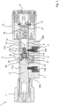
- Figure 1 shows a side sectional view of an electrical locking unit 1 in the form of a locking cylinder 2 for a lock (not shown) in the uncoupled state.
- the locking cylinder 2 has a cylinder housing 3 in which a locking element 4 in the form of a locking bit 4a is rotatably mounted.
- the locking bit 4a typically has a finger 5 protruding from the rotational axis of the locking bit 4a for actuating a bolt of a lock when the locking cylinder 2 is installed in a lock.
- a knob shaft 6 is also inserted into the cylinder housing 3 and mounted there for rotation.
- An operating knob 7 can be attached to the end of the knob shaft 6 protruding from the cylinder housing 3.
- a coupling device 8 is installed in this knob shaft 6, which is designed to mechanically couple the knob shaft 6 to the locking bit 4a.
- This coupling device 8 has an electric motor 9 with a shaft 10 onto which a worm shaft 11 is pressed.
- the worm shaft 11 can also be formed integrally with the shaft 10 of the electric motor 9.
- the worm shaft 11 has a threaded web that extends circumferentially around the circumference of the worm shaft 11 in the direction of extension of the worm shaft 11, i.e., a helical thread.
- the electric motor 9 is controlled by control electronics 12.
- This control electronics 12 can preferably have a radio signal receiver 13 for wirelessly receiving opening and closing signals.
- the radio signal receiver 13 can be configured for near-field (NFC, e.g., RFID) and/or far-field reception (e.g., Bluetooth, ZigBee, Wi-Fi).
- the coupling device 8 is installed in a knob shaft 14 for rotation therewith.
- An actuating knob 15 is mounted on the knob shaft 14 for rotation therewith.
- the knob shafts 6, 14 are each installed in an aligned bore of the cylinder housing 3 and are each positively secured against axial displacement by a locking screw 16a, 16b.
- the knob shafts 6, 14 have a circumferential groove 17a, 17b on their outer circumference, into which the respective locking screw 16a, 16b engages without exerting a contact force in the radial direction on the respective knob shaft 6, 14. This ensured that the knob shafts 6, 14 are mounted in the cylinder housing 3 so that they can rotate around their axis.
- the coupling device 8 has a spring element 18 in the form of a helical spring (e.g., a compression spring).
- the proximal end portion of the spring element 18 closest to the electric motor 9 can engage the worm shaft 11 with at least a single wrap to cause an axial displacement upon rotation of the worm shaft 11.
- the distal end of the spring element 18 is connected in a rotationally fixed manner to a coupling member 19.
- the coupling member 19 has a spring retaining core 20 and a coupling element 21.
- the spring retaining core 20 is received with a press fit in a receiving opening of the coupling element 21.
- the distal end of the spring element 18 wraps around the spring retaining core 20 and is mounted in a form-fitting and force-fitting manner between the spring retaining core 20 and the inner wall of the coupling element 21 surrounding the spring retaining core 20. The distal end of the spring element 18 is thus connected to the coupling member 19.
- the coupling member 19 is mounted axially displaceably in the knob shaft 14 and has an outer contour that, together with an inner wall contour of the knob shaft 14, forms a stop to prevent rotation of the coupling member 19 in the interior of the knob shaft 14.
- the outer contour of the coupling element 21 can, for example, be polygonal.
- the inner wall of the knob shaft 14 has a corresponding polygonal cross-section in the section in which the coupling member 19 is received.
- the proximal end section 26 of the spring element opposite the coupling member 19 has at least one turn at the outgoing end, preferably a wrap in the range of 360° to 720° (1-fold to 2-fold wrap), and particularly preferably of approximately 500° to 700°, a diameter which is reduced compared to the adjoining section, through which the proximal end section 26 enters the space between the helical turns of the worm shaft 11 and thus engages with the web-shaped threads of the worm shaft 11.
- the proximal end section 26 of the spring element 18 can be guided in the space between the helical winding of the worm shaft 8 in order to tension or relax the spring element 18 during rotation of the worm shaft 8 and thus to move the coupling member 19 axially back and forth along the longitudinal axis of the knob shaft 14.
- the spring element 10 is tensioned or relaxed, and the coupling member 19 at the distal end of the spring element 10 is moved in the direction of the interior of the knob shaft 14 or out of the front opening of the knob shaft 14 for engagement with the locking bit 4a.
- the coupling member 19 is largely accommodated in the interior of the knob shaft 14 and spaced from a coupling contour 22 of the locking element 4.
- the engaged state is reached at the latest when the coupling member 19 protrudes as far as possible from the knob shaft 14 on the front side and is thereby positively connected to the coupling contour 22 of the locking element 4, for example the locking bit 4a.
- the proximal end portion 26 of the spring element 19 is in freewheeling mode and is not engaged with the screw shaft 11.
- the at least single wrap is located behind the helical winding on a tubular portion of the worm shaft 11, which is present between the front end wall of the electric motor 9 and the beginning of the helical winding.
- Figure 2 shows a side view of the locking cylinder 2 from Figure 1 in the area of the coupling device 8.
- the coupling member 19 is constructed in several parts to facilitate assembly. It comprises the polygonal coupling element 21 with a receiving opening 23 into which the spring retaining core 20 is received.
- the connection between the spring retaining core 20 and the coupling element 21 can be achieved by a press fit.
- a material connection e.g., by welding, or a positive and possibly non-positive connection by screwing, pinning, or riveting is also conceivable.
- the coupling element 21 it is also conceivable for the coupling element 21 to be constructed in one piece with the spring retaining core 20.
- the distal end section 24 of the spring element wraps around a support section 25 projecting into the receiving opening 23 of the coupling element 21 towards the electric motor 9 with at least one wrap, preferably with more than two wraps, ie with a wrap angle of more than 720°.
- the distal end 24 is clamped force-fittingly onto the support section 25 and positively received in the space between the support section 25 and the inner wall of the coupling element 21 delimiting the receiving opening 23.
- the proximal end 26 of the spring element 18 opposite the coupling member 19 is in freewheeling mode without engaging with the helical winding of the worm shaft 11.
- the reduced-diameter proximal end section 26 is positioned between the beginning of the helical winding of the worm shaft 11 and the end wall of the electric motor 9.
- the diameter of the section of the spring element 18 that adjoins the proximal end section 26 and extends to the distal end section 24 is larger than the outer diameter of the helical winding of the worm shaft 11.
- the spring element 18 engages positively with the helical winding of the worm shaft 11 only in the region of the proximal end section 26.
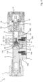
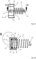
- Figure 3 shows a side sectional view of a locking cylinder 2 with pre-tensioned spring element 18.
- the coupling contour of the coupling member 19 is not yet precisely aligned with the corresponding coupling contour 22 of the closure element 4.
- the coupling member 19 is therefore not yet axially displaced far enough to engage with the closure element 4.
- the spring element 18 is already preloaded by the proximal end section 26 being moved away from the electric motor 9 and toward the coupling member 19 by rotation of the worm shaft 11.
- the wraps of the spring element 18 positioned between the thread flanks of the helical winding are moved axially.
- Figure 4 shows a side view of the locking cylinder 2 from Figure 3 in the area of the coupling device 8 in the preloaded state.
- the worm shaft 11 is again in freewheeling mode, as the proximal end section 26 is now disengaged from the thread flanks of the helical winding at the end of the helical winding and between the end of the helical winding and the coupling member 19 on a tubular end portion of the worm shaft 11.
- Figure 5 shows a side sectional view of a locking cylinder 2 in the engaged state.
- the coupling contour of the coupling member 19 is now aligned by the relative rotation of the knob shafts 6, 14 to one another such that it is adapted to the corresponding coupling contour 22 of the locking element 4.
- This allows the polygonal coupling member 19 to engage a correspondingly polygonal recess in the locking bit 4a. This creates a positive connection between the coupling member 19 and the locking element 4.
- the spring element 18 is no longer engaged with the worm shaft 11.
- the worm shaft 11 is in freewheel mode, in particular, when one of the end positions is reached and the electric motor 9 continues to rotate. This ensures a defined pressure force of the spring element 18. In addition, power consumption during idle operation is reduced. Overloading of the spring element 18 is prevented.
- the end positions simplify temperature compensation. At lower temperatures, the guide is stiffer, so that the electric motor 9 must be operated for a longer time than at higher temperatures. The running time of the electric motor 9 no longer needs to be adjusted - or not as precisely - due to the freewheel in the end positions.
- a drilling protection element 27 is arranged in the interior of the knob shaft 14.
- the drilling protection element 27 separates the unsafe side facing the actuating knob 15 from the unsafe side of the locking cylinder 2 located behind the drilling protection element 27, as seen from the actuating knob 15, on which the coupling device 8 is located.
- the cylinder housing 3 can optionally be extended by means of extension discs, which are screwed onto the front side adjacent to the actuating knob 7, 15.
- the cylinder housing 3 has threaded holes 28a, 28b on the front side to accommodate fastening screws for the extension discs.
- the operating knob 15 can be fixed at several positions on the knob shaft 14.
- locking grooves 29 are provided on the knob shaft 14 in the specified locking positions.
- Figure 6 shows a side view of the locking cylinder 2 from Figure 5 in the area of the coupling device 8.
- Figure 7 shows a front view of the polygonal coupling element 21 with the section line BB.
- the coupling element 21 has a central receiving opening 23 into which the spring retaining core 20 is installed.
- the outer circumference has a polygonal contour with, for example, three protruding elevations 30. Additional recesses 32 can optionally be provided in the reduced-diameter intermediate areas 31.
- Figure 8 shows a side sectional view of the coupling member 19 with spring retaining core 20 and coupling element 21 and spring element 18 non-positively connected to a support section 25 of the spring retaining core 20 in section BB.
- the diameter of the spring element 18 in the proximal end region 26 is significantly reduced over more than one wrap, i.e., more than 360°.
- the proximal end region 26 extends over approximately 400° to 540°, i.e., more than one to 1.5 wraps.
- distal end portion 24 is non-positively connected to the support portion 25 of the spring retaining core 20 by more than two turns.
- the distal end portion 24 can also rest against an end wall of the spring retaining core 20.
- the spring retaining core 20 is received in the receiving opening 23 and pressed with the coupling element 21.
- the coupling element 21 has an internal thread and the spring retaining core 20 has a corresponding external thread and the spring retaining core 20 is screwed into the coupling element 21.
- Other types of fastening the spring retaining core 20 to the coupling element 21 are also conceivable.
- Figure 9 shows a side view of the coupling member 19 from Figure 8 with built-in spring element 18.
- the polygonal outer contour of the coupling element 21 is visible.
- Figure 10 shows a side view of another embodiment of a coupling member 19 with spring element 18 connected thereto and a section line CC.
- the pressure element 4b has protruding lugs 33 that are received in a guide opening to support the pressure element 4b in a linearly displaceable and rotationally fixed manner.
- the spring element 18 is received in a receiving opening 23 of the pressure element 4b.
- Deformation regions 34 are present on the pressure element 4b, which, through deformation, provide a positive connection of the spring element 18 to the pressure element 4b.
- Figure 11 shows a side sectional view of the coupling member 19 from Figure 10 in section CC with the opposing deformation regions 34.
- the deformation regions 34 have a blind hole 35, the edge regions of which can be caulked to the inner distal end portion 24 of the spring element 18 by the application of force.
- a punch is inserted into the blind holes 35, which deforms the inner wall 36 of the coupling element 19 adjacent to the distal end portion 24.
- the polygonal coupling member 19 can have blind holes 35 on the outer circumference, which by deforming the inner walls 36 delimiting the blind holes 35, the distal end section 24 is fastened to the coupling member 19.
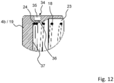
- Figure 12 shows a side cut-out view of the coupling member 19 from Figure 11 in the area of a deformation area 34 with a spring element 18 positively connected there.
- the inner wall 36 of the blind hole 35 is deformed into the receiving opening 23 of the coupling member 19 in order to compress the outer diameter of the windings of the spring element 18 at the distal end section 24 and in this way to receive the distal end section 24 in a form-fitting and friction-locking manner in the interior of the coupling member 19.
- the diameter of the receiving opening 23 can be conically widened in front of the section with the deformation areas 34.
- the distal end portion 24 of the spring element 18 can rest against the end wall 37 in the interior of the coupling member 19.
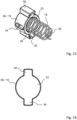
- Figure 13 shows a perspective view of a cylindrical coupling member 19 with a pair of cuboid-shaped projections 38 on the outer circumference of the cylindrical base body.
- the coupling member 19 has a central receiving opening 23 into which the spring element 18 is installed. At least one deformation region 34 with a recess 39 is provided on the outer circumference. A blind hole 35 in the recess 39 can be deformed into the interior of the coupling member 19 in order to positively secure the distal end 24 of the spring element 18 to the coupling member 19.
- Figure 14 shows a front view of the cylindrical coupling member 19 from Figure 13 .
- a pair of cuboid-shaped projections 38 protrude in opposite directions from the cylindrical outer contour of the base body.
- the projections 38 may have chamfered edges and a slightly curved radial outer surface.
- Figure 16 shows a side sectional view of the coupling member 19 from Figure 15 . It can be seen that on each opposite side there is a recess 39 with a blind hole 35 in a deformation region 34. The blind hole 35 is deformed into the receiving opening 23, i.e., into the interior of the coupling member 19, with a projecting nose in each case engaging with the distal end portion 24 of the spring element 18. As a result, the spring element 18 is connected to the coupling member 19 in a form-fitting and, if necessary, also a force-fitting manner.
- Figure 17 shows a side cut-out view of the coupling member 19 from Figure 16 in the region of a deformation region with a spring element 18 positively connected there. It can be seen that the distal end section 24 of the spring element 18 rests against the end wall 37 of the receiving opening 23.
- the nose formed in the deformation region 34 is clearly visible, which nose rests on the outer circumference of a spring coil and positively secures, for example, two spring coils 24 between the end wall 37 and the nose or the deformation region 34.
Landscapes
- Physics & Mathematics (AREA)
- Electromagnetism (AREA)
- Lock And Its Accessories (AREA)
Applications Claiming Priority (1)
| Application Number | Priority Date | Filing Date | Title |
|---|---|---|---|
| DE102023136459.6A DE102023136459A1 (de) | 2023-12-22 | 2023-12-22 | Elektrische Schließeinheit |
Publications (1)
| Publication Number | Publication Date |
|---|---|
| EP4575150A1 true EP4575150A1 (fr) | 2025-06-25 |
Family
ID=93926572
Family Applications (1)
| Application Number | Title | Priority Date | Filing Date |
|---|---|---|---|
| EP24221066.4A Pending EP4575150A1 (fr) | 2023-12-22 | 2024-12-18 | Unité de fermeture électrique |
Country Status (3)
| Country | Link |
|---|---|
| US (1) | US20250207434A1 (fr) |
| EP (1) | EP4575150A1 (fr) |
| DE (1) | DE102023136459A1 (fr) |
Citations (8)
| Publication number | Priority date | Publication date | Assignee | Title |
|---|---|---|---|---|
| WO1998015703A1 (fr) | 1996-10-08 | 1998-04-16 | Lucky Lock Ltd. | Serrure electromecanique |
| EP1522658B1 (fr) | 2003-10-10 | 2006-08-16 | CISA S.p.A. | Serrure électrique avec support magnétique de l'élément de couplage |
| EP1576246B1 (fr) | 2002-12-23 | 2006-08-30 | Kaba AG | Dispositif de verrouillage |
| US20130305792A1 (en) * | 2012-05-15 | 2013-11-21 | Wfe Technology Corp. | Actuating motor set of electronic |
| EP2927395A1 (fr) | 2014-04-03 | 2015-10-07 | DOM Sicherheitstechnik GmbH & Co. KG | Système de couplage de barillet à ressort double |
| WO2018165121A1 (fr) * | 2017-03-08 | 2018-09-13 | Sargent Manufacturing Company | Mécanisme de verrouillage pour serrure encastrée |
| DE102019113666B4 (de) | 2019-05-22 | 2022-09-29 | ASTRA Gesellschaft für Asset Management mbH & Co. KG | Elektrischer Schließzylinder für ein Schloss |
| US20230332433A1 (en) * | 2022-04-15 | 2023-10-19 | Digilock Asia Ltd. | Electronically Operated Lock Cylinder |
Family Cites Families (8)
| Publication number | Priority date | Publication date | Assignee | Title |
|---|---|---|---|---|
| GB1559486A (en) * | 1976-12-01 | 1980-01-23 | Breneman Inc | Window blind roller and fittings |
| US20080072636A1 (en) * | 2006-09-22 | 2008-03-27 | Assa Abloy Identification Technology Group Ab | Knob operated electromechanical lock cylinder |
| TWM365969U (en) * | 2008-11-14 | 2009-10-01 | bang-zheng Liu | Electric lock-latch driver |
| DE102009026176A1 (de) * | 2009-07-15 | 2011-01-27 | M.Van Der Wal Holding B.V. | Längenveränderbarer Knaufschließzylinder |
| US8302438B2 (en) * | 2009-11-12 | 2012-11-06 | Pang-Cheng Lui | Driving device for an electric lock latch |
| TWM451410U (zh) * | 2012-09-21 | 2013-04-21 | Tong Lung Metal Ind Co Ltd | 電子鎖的傳動機構 |
| EP2860331B1 (fr) * | 2013-10-08 | 2016-08-03 | Assa Oem AB | Dispositif de poignée |
| US20240218704A1 (en) * | 2023-01-04 | 2024-07-04 | ASSA ABLOY Residential Group, Inc. | Clutch for a lock |
-
2023
- 2023-12-22 DE DE102023136459.6A patent/DE102023136459A1/de active Pending
-
2024
- 2024-12-18 US US18/985,641 patent/US20250207434A1/en active Pending
- 2024-12-18 EP EP24221066.4A patent/EP4575150A1/fr active Pending
Patent Citations (8)
| Publication number | Priority date | Publication date | Assignee | Title |
|---|---|---|---|---|
| WO1998015703A1 (fr) | 1996-10-08 | 1998-04-16 | Lucky Lock Ltd. | Serrure electromecanique |
| EP1576246B1 (fr) | 2002-12-23 | 2006-08-30 | Kaba AG | Dispositif de verrouillage |
| EP1522658B1 (fr) | 2003-10-10 | 2006-08-16 | CISA S.p.A. | Serrure électrique avec support magnétique de l'élément de couplage |
| US20130305792A1 (en) * | 2012-05-15 | 2013-11-21 | Wfe Technology Corp. | Actuating motor set of electronic |
| EP2927395A1 (fr) | 2014-04-03 | 2015-10-07 | DOM Sicherheitstechnik GmbH & Co. KG | Système de couplage de barillet à ressort double |
| WO2018165121A1 (fr) * | 2017-03-08 | 2018-09-13 | Sargent Manufacturing Company | Mécanisme de verrouillage pour serrure encastrée |
| DE102019113666B4 (de) | 2019-05-22 | 2022-09-29 | ASTRA Gesellschaft für Asset Management mbH & Co. KG | Elektrischer Schließzylinder für ein Schloss |
| US20230332433A1 (en) * | 2022-04-15 | 2023-10-19 | Digilock Asia Ltd. | Electronically Operated Lock Cylinder |
Also Published As
| Publication number | Publication date |
|---|---|
| US20250207434A1 (en) | 2025-06-26 |
| DE102023136459A1 (de) | 2025-06-26 |
Similar Documents
| Publication | Publication Date | Title |
|---|---|---|
| EP1636454B1 (fr) | Barillet electromagnetique | |
| EP0175996B1 (fr) | Unité d'entraînement notamment pour le déplacement de glaces, de toits ouvrants, de sièges et d'accessoires d'automobiles similaires | |
| EP2909399B1 (fr) | Système doté d'une partie d'actionnement de porte et d'un barillet de serrure | |
| EP3207197B1 (fr) | Élément d'actionnement pour une serrure à palastre | |
| DE29820711U1 (de) | Drehriegelverschluß mit Zugeinrichtung | |
| DE102010018243B4 (de) | Schließzylinderanordnung | |
| EP1719861B1 (fr) | Serrure cylindrique pour un système de verrouillage électronique | |
| DE3744274C2 (de) | Elektromotor, insbesondere elektrischer Kleinmotor | |
| EP0175049B1 (fr) | Tourniquet susceptible d'être manoeuvré par une clé à tube | |
| DE10324690A1 (de) | Ferngesteuert freigebbarer Schließzylinder | |
| DE102007011554B4 (de) | Koppeleinheit für elektronische Schließ-Systeme | |
| DE602004003658T2 (de) | Schlüssel zur Betätigung eines Schlosses | |
| DE102019113666B4 (de) | Elektrischer Schließzylinder für ein Schloss | |
| EP2345782B1 (fr) | Cylindre anti-panique | |
| DE29722488U1 (de) | Vorreiberverschluß für dickwandige Türen, Klappen o.dgl. | |
| DE102013212508B4 (de) | Türanlage | |
| EP4575150A1 (fr) | Unité de fermeture électrique | |
| EP3290622A1 (fr) | Dispositif de compensation d'une différence de longueur entre une serrure à cylindre et un vantail | |
| DE102008028800B4 (de) | Baugruppe für ein Türschloss, die zum Sperren oder Freigeben des Türschlosses vorgesehen ist | |
| EP3502380B1 (fr) | Dispositif de fixation d'un ouvre-porte | |
| EP0941549B1 (fr) | Interrupteur de securite | |
| EP1674764A1 (fr) | Ecrou d'engrenage pour dispositif actionneur linéaire | |
| EP3741933B1 (fr) | Dispositif de fermeture | |
| EP2597229A1 (fr) | Elément d'embrayage, système de boulon, mécanisme de rappel, boîtier de cylindre, dispositif de cylindre, cylindre de fermeture et serrure à mortaiser ainsi que procédé de rappel et de montage associés | |
| EP1048803A2 (fr) | Dispositif de fermeture pour une serrure avec ouvertures d'insertion disposées de chaque côté |
Legal Events
| Date | Code | Title | Description |
|---|---|---|---|
| PUAI | Public reference made under article 153(3) epc to a published international application that has entered the european phase |
Free format text: ORIGINAL CODE: 0009012 |
|
| STAA | Information on the status of an ep patent application or granted ep patent |
Free format text: STATUS: THE APPLICATION HAS BEEN PUBLISHED |
|
| AK | Designated contracting states |
Kind code of ref document: A1 Designated state(s): AL AT BE BG CH CY CZ DE DK EE ES FI FR GB GR HR HU IE IS IT LI LT LU LV MC ME MK MT NL NO PL PT RO RS SE SI SK SM TR |
|
| STAA | Information on the status of an ep patent application or granted ep patent |
Free format text: STATUS: REQUEST FOR EXAMINATION WAS MADE |
|
| 17P | Request for examination filed |
Effective date: 20250701 |