EP4575152A1 - Contre-boîte - Google Patents
Contre-boîte Download PDFInfo
- Publication number
- EP4575152A1 EP4575152A1 EP24215552.1A EP24215552A EP4575152A1 EP 4575152 A1 EP4575152 A1 EP 4575152A1 EP 24215552 A EP24215552 A EP 24215552A EP 4575152 A1 EP4575152 A1 EP 4575152A1
- Authority
- EP
- European Patent Office
- Prior art keywords
- ejector
- lock
- leaf
- distance
- bolt
- Prior art date
- Legal status (The legal status is an assumption and is not a legal conclusion. Google has not performed a legal analysis and makes no representation as to the accuracy of the status listed.)
- Pending
Links
Images



Classifications
-
- E—FIXED CONSTRUCTIONS
- E05—LOCKS; KEYS; WINDOW OR DOOR FITTINGS; SAFES
- E05B—LOCKS; ACCESSORIES THEREFOR; HANDCUFFS
- E05B63/00—Locks or fastenings with special structural characteristics
- E05B63/24—Arrangements in which the fastening members which engage one another are mounted respectively on the wing and the frame and are both movable, e.g. for release by moving either of them
- E05B63/248—Arrangements in which the fastening members which engage one another are mounted respectively on the wing and the frame and are both movable, e.g. for release by moving either of them the striker being movable for latching, and pushed back by a member on the wing for unlatching, or vice versa
-
- E—FIXED CONSTRUCTIONS
- E05—LOCKS; KEYS; WINDOW OR DOOR FITTINGS; SAFES
- E05B—LOCKS; ACCESSORIES THEREFOR; HANDCUFFS
- E05B63/00—Locks or fastenings with special structural characteristics
- E05B63/0056—Locks with adjustable or exchangeable lock parts
-
- E—FIXED CONSTRUCTIONS
- E05—LOCKS; KEYS; WINDOW OR DOOR FITTINGS; SAFES
- E05C—BOLTS OR FASTENING DEVICES FOR WINGS, SPECIALLY FOR DOORS OR WINDOWS
- E05C7/00—Fastening devices specially adapted for two wings
- E05C7/04—Fastening devices specially adapted for two wings for wings which abut when closed
-
- E—FIXED CONSTRUCTIONS
- E05—LOCKS; KEYS; WINDOW OR DOOR FITTINGS; SAFES
- E05B—LOCKS; ACCESSORIES THEREFOR; HANDCUFFS
- E05B65/00—Locks or fastenings for special use
- E05B65/10—Locks or fastenings for special use for panic or emergency doors
- E05B65/1086—Locks with panic function, e.g. allowing opening from the inside without a ley even when locked from the outside
Definitions
- the invention relates to a passive leaf lock with such a strike box and to a locking system for a double-leaf door with, on the one hand, a passive leaf lock arranged on the active leaf and, on the other hand, a passive leaf lock arranged on the passive leaf.
- double-leaf doors are those doors which have a so-called active leaf on the one hand and a so-called passive leaf on the other hand. wherein the inactive leaf is closed during normal operation and consequently remains in a closed position, while the active leaf - as with a conventional, single-leaf door - is opened and closed for passage.
- the inactive leaf lock is arranged with the strike box, which is equipped with an actuating device, e.g. a lock nut, so that the inactive leaf lock can also be unlocked via the lock nut and thus the inactive leaf can be opened.
- the invention preferably relates to a strike box for an inactive leaf lock with a panic function, in which at least one handle, e.g. a panic handle, or a panic bar is connected to the (rotatable) lock nut.
- a panic handle e.g. a panic handle
- a panic bar is connected to the (rotatable) lock nut.
- the lock nut By actuating the lock nut (e.g. via the panic handle or the panic bar), both an upper locking bar connected to the strike box and a lower locking bar connected to the strike box are moved and preferably retracted (along the longitudinal direction of the lock) towards the strike box and thus unlocked.
- the locking bars connected to the strike box engage in corresponding locking receptacles, which are arranged, for example, on the top side of the door frame or lintel and on the bottom side of the floor.
- the active leaf lock arranged in or on the active leaf has several locking elements, e.g. a latch and a bolt, which engage in the strike box of the passive leaf, which is also in the closed position, when the active leaf is closed.
- the strike box according to the invention or the inactive leaf lock according to the invention is designed for panic operation.
- several ejectors are integrated into the strike box, e.g. a latch ejector and a bolt ejector, which are activated when the handle or the panic bar on the Inactive leafs push the locking elements of the active leaf engaging in the strike box, e.g., the deadbolt and latch, out of the strike box and preferably back into the housing of the active leaf lock.
- the ejectors are moved, e.g., in a working direction oriented transversely to the longitudinal direction of the lock and preferably retracted from the housing of the inactive leaf lock.
- the ejector function ensures that the opening of the inactive leaf, e.g., during a panic operation, is not disrupted by the locking elements of the active leaf lock engaging in the strike box of the inactive leaf lock.
- a strike box for a passive leaf lock with an upper rod connection for connecting an upper connecting rod and a lower rod connection for connecting a lower connecting rod as well as a lock mechanism with a switching nut for actuating the rod connection for retracting and extending is known, for example, from DE 20 2013 001 053 U1
- the switching nut By operating the switching nut, the rod connections are retracted from their extended position to the retracted position via the lock mechanism, and a latch ejector and a bolt ejector are activated and swung out.
- the adapter is positively connected to the ejector, with the positive connection being formed by a tenon with a tenon and a tenon receptacle.
- the adapter itself is designed as a plate, and the tenon and tenon receptacle are embossed.
- a strike box in which the bolt slide or bolt ejector is designed as a switchable bolt slide which can be switched between a rigid state and a soft state and, when the active sash lock is unlocked, a rebate air shutter which precedes the bolt slide switches the bolt slide from rigid to soft upon contact or during contact with the face plate of the active sash lock or a door sash face plate.
- rebate air gap compensation which can be used to react to varying rebate air gap dimensions and thus also to a varying gap dimension between the faceplate of the active leaf lock and the faceplate of the passive leaf lock.
- the distance dimension also known as “distance,” must be distinguished from the rebate clearance and the gap dimension. This refers to the active leaf lock.
- the distance dimension defines the distance between the lock follower and the profile cylinder of the active leaf lock, which can be a mortise lock with a lock follower and profile cylinder or a center lock of a multi-point locking system. Active leaf locks and their locks are offered with different distances, in practice, for example, with “distance 72" or “distance 92" and consequently with a distance between the lock follower and the profile cylinder of 72 mm or 92 mm.
- the distance between the locking elements e.g., the deadbolt and latch
- the distance between the deadbolt and latch is therefore greater than in a lock with a distance of 72.
- the invention is based on the object of creating a strike box for a passive leaf lock of a double-leaf door, which, with an economical and functional design, enables simple and functionally reliable adaptation to a moving leaf lock and, in particular, to various moving leaf locks with different distance dimensions.
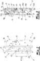
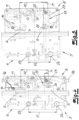
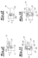
- the ejector is designed such that the ejector element can be fastened to the carrier in different positions (in particular with respect to the longitudinal direction of the lock and consequently height positions) in order to enable adaptation of the strike box to the respective distance of the active leaf lock.
- the ejector element of the first ejector can be mounted on the one hand in a first, e.g., upper position with a first distance (along the longitudinal direction of the lock) from the second ejector and on the other hand in a second, e.g., lower position with be attachable to the support at a second distance from the second ejector, wherein the second distance is greater than the first distance by a differential dimension.
Landscapes
- Engineering & Computer Science (AREA)
- Structural Engineering (AREA)
- Mechanical Engineering (AREA)
- Physics & Mathematics (AREA)
- Electromagnetism (AREA)
- Supports Or Holders For Household Use (AREA)
- Lock And Its Accessories (AREA)
Applications Claiming Priority (1)
| Application Number | Priority Date | Filing Date | Title |
|---|---|---|---|
| DE102023135780.8A DE102023135780A1 (de) | 2023-12-19 | 2023-12-19 | Gegenkasten |
Publications (1)
| Publication Number | Publication Date |
|---|---|
| EP4575152A1 true EP4575152A1 (fr) | 2025-06-25 |
Family
ID=93656063
Family Applications (1)
| Application Number | Title | Priority Date | Filing Date |
|---|---|---|---|
| EP24215552.1A Pending EP4575152A1 (fr) | 2023-12-19 | 2024-11-26 | Contre-boîte |
Country Status (2)
| Country | Link |
|---|---|
| EP (1) | EP4575152A1 (fr) |
| DE (1) | DE102023135780A1 (fr) |
Cited By (1)
| Publication number | Priority date | Publication date | Assignee | Title |
|---|---|---|---|---|
| EP4775769A1 (fr) * | 2025-01-10 | 2026-07-15 | ASSA ABLOY Sicherheitstechnik GmbH | Serrure à pêne dormant avec protection contre la manipulation |
Citations (4)
| Publication number | Priority date | Publication date | Assignee | Title |
|---|---|---|---|---|
| DE202013001053U1 (de) | 2013-01-11 | 2013-03-25 | Wilh. Schlechtendahl & Söhne GmbH & Co. KG | Gegenkasten oder Einsteckschloss |
| DE102013100275A1 (de) * | 2013-01-11 | 2014-07-17 | Eco Schulte Gmbh & Co. Kg | Treibriegelschloss mit überdrückbarem Riegelschieber |
| EP2752539B2 (fr) | 2013-01-07 | 2020-03-25 | BKS GmbH | Crémone espagnolette |
| DE102018115985B4 (de) | 2018-07-02 | 2021-12-09 | Assa Abloy Sicherheitstechnik Gmbh | Schlossgegenkasten für ein Aktivflügelschloss mit Falzluftausgleich |
Family Cites Families (1)
| Publication number | Priority date | Publication date | Assignee | Title |
|---|---|---|---|---|
| DE102013001818B4 (de) * | 2013-01-11 | 2019-12-19 | Wilh. Schlechtendahl & Söhne GmbH & Co. KG | Gegenkasten |
-
2023
- 2023-12-19 DE DE102023135780.8A patent/DE102023135780A1/de active Pending
-
2024
- 2024-11-26 EP EP24215552.1A patent/EP4575152A1/fr active Pending
Patent Citations (4)
| Publication number | Priority date | Publication date | Assignee | Title |
|---|---|---|---|---|
| EP2752539B2 (fr) | 2013-01-07 | 2020-03-25 | BKS GmbH | Crémone espagnolette |
| DE202013001053U1 (de) | 2013-01-11 | 2013-03-25 | Wilh. Schlechtendahl & Söhne GmbH & Co. KG | Gegenkasten oder Einsteckschloss |
| DE102013100275A1 (de) * | 2013-01-11 | 2014-07-17 | Eco Schulte Gmbh & Co. Kg | Treibriegelschloss mit überdrückbarem Riegelschieber |
| DE102018115985B4 (de) | 2018-07-02 | 2021-12-09 | Assa Abloy Sicherheitstechnik Gmbh | Schlossgegenkasten für ein Aktivflügelschloss mit Falzluftausgleich |
Cited By (1)
| Publication number | Priority date | Publication date | Assignee | Title |
|---|---|---|---|---|
| EP4775769A1 (fr) * | 2025-01-10 | 2026-07-15 | ASSA ABLOY Sicherheitstechnik GmbH | Serrure à pêne dormant avec protection contre la manipulation |
Also Published As
| Publication number | Publication date |
|---|---|
| DE102023135780A1 (de) | 2025-06-26 |
Similar Documents
| Publication | Publication Date | Title |
|---|---|---|
| EP1932989B1 (fr) | Système de fermeture pour portes, fenêtres ou analogues, en particulier crémone-serrure à fonction d'urgence et de verrouillage à plusieurs points | |
| EP0849425A1 (fr) | Dispositif de déverrouillage et verrouillage pour une porte à deux battants | |
| EP0799957A2 (fr) | Barre anti-panique réversible pour portes de secours | |
| DE9208526U1 (de) | Schloß, insbesondere Einsteckschloß für eine Außentür | |
| EP2339096B1 (fr) | Serrure à crémone dotée d'une fonction anti-panique et d'un verrouillage multiple | |
| DE102023135780A1 (de) | Gegenkasten | |
| EP0471976B1 (fr) | Crémone | |
| DE19652599C2 (de) | Ent- und Verriegelung für eine einen Standflügel und einen Gangflügel aufweisende Tür | |
| EP3222801B1 (fr) | Système de verrouillage avec verrou pour coffres-forts | |
| DE4333786C2 (de) | Schloßmechanismus | |
| EP2327851A2 (fr) | Serrure avec une tige coulissante déclenchable | |
| EP2060714A2 (fr) | Crémone-serrure | |
| EP4116529B1 (fr) | Unité de verrouillage | |
| DE3920498C2 (de) | Mehrfachverriegelung | |
| EP1672153B1 (fr) | Serrure avec pêne dormant et dispositif de commande du pêne dormant | |
| EP0974721B1 (fr) | Serrure à plusieurs pênes | |
| AT509464B1 (de) | Schloss | |
| DE3205054C2 (fr) | ||
| EP0806534B1 (fr) | Crémone | |
| EP4512981A1 (fr) | Contre-boîte pour une fermeture à battant fixe | |
| EP4060152B1 (fr) | Mécanisme d'actionnement pour une fenêtre ou une porte à fonction de déverrouillage d'urgence | |
| EP2615229A2 (fr) | Installation de fermeture | |
| EP4116527B1 (fr) | Serrure de sécurité | |
| EP2683891A2 (fr) | Serrure de meuble | |
| WO1993004253A1 (fr) | Porte de securite et dispositif de securite pour le montage dans une porte |
Legal Events
| Date | Code | Title | Description |
|---|---|---|---|
| PUAI | Public reference made under article 153(3) epc to a published international application that has entered the european phase |
Free format text: ORIGINAL CODE: 0009012 |
|
| STAA | Information on the status of an ep patent application or granted ep patent |
Free format text: STATUS: REQUEST FOR EXAMINATION WAS MADE |
|
| 17P | Request for examination filed |
Effective date: 20250522 |
|
| AK | Designated contracting states |
Kind code of ref document: A1 Designated state(s): AL AT BE BG CH CY CZ DE DK EE ES FI FR GB GR HR HU IE IS IT LI LT LU LV MC ME MK MT NL NO PL PT RO RS SE SI SK SM TR |