EP4575291A1 - Raccords mécaniques pour matériau à base de pvc - Google Patents
Raccords mécaniques pour matériau à base de pvc Download PDFInfo
- Publication number
- EP4575291A1 EP4575291A1 EP24221067.2A EP24221067A EP4575291A1 EP 4575291 A1 EP4575291 A1 EP 4575291A1 EP 24221067 A EP24221067 A EP 24221067A EP 4575291 A1 EP4575291 A1 EP 4575291A1
- Authority
- EP
- European Patent Office
- Prior art keywords
- pipe
- ring
- nut
- main body
- grip ring
- Prior art date
- Legal status (The legal status is an assumption and is not a legal conclusion. Google has not performed a legal analysis and makes no representation as to the accuracy of the status listed.)
- Pending
Links
Images


Classifications
-
- F—MECHANICAL ENGINEERING; LIGHTING; HEATING; WEAPONS; BLASTING
- F16—ENGINEERING ELEMENTS AND UNITS; GENERAL MEASURES FOR PRODUCING AND MAINTAINING EFFECTIVE FUNCTIONING OF MACHINES OR INSTALLATIONS; THERMAL INSULATION IN GENERAL
- F16L—PIPES; JOINTS OR FITTINGS FOR PIPES; SUPPORTS FOR PIPES, CABLES OR PROTECTIVE TUBING; MEANS FOR THERMAL INSULATION IN GENERAL
- F16L19/00—Joints in which sealing surfaces are pressed together by means of a member, e.g. a swivel nut, screwed on, or into, one of the joint parts
- F16L19/06—Joints in which sealing surfaces are pressed together by means of a member, e.g. a swivel nut, screwed on, or into, one of the joint parts in which radial clamping is obtained by wedging action on non-deformed pipe ends
- F16L19/065—Joints in which sealing surfaces are pressed together by means of a member, e.g. a swivel nut, screwed on, or into, one of the joint parts in which radial clamping is obtained by wedging action on non-deformed pipe ends the wedging action being effected by means of a ring
-
- F—MECHANICAL ENGINEERING; LIGHTING; HEATING; WEAPONS; BLASTING
- F16—ENGINEERING ELEMENTS AND UNITS; GENERAL MEASURES FOR PRODUCING AND MAINTAINING EFFECTIVE FUNCTIONING OF MACHINES OR INSTALLATIONS; THERMAL INSULATION IN GENERAL
- F16L—PIPES; JOINTS OR FITTINGS FOR PIPES; SUPPORTS FOR PIPES, CABLES OR PROTECTIVE TUBING; MEANS FOR THERMAL INSULATION IN GENERAL
- F16L49/00—Connecting arrangements, e.g. joints, specially adapted for pipes of brittle material, e.g. glass, earthenware
- F16L49/06—Joints in which sealing surfaces are pressed together by means of a member, e.g. swivel nut, screwed on, or into, one of the joint parts
-
- F—MECHANICAL ENGINEERING; LIGHTING; HEATING; WEAPONS; BLASTING
- F16—ENGINEERING ELEMENTS AND UNITS; GENERAL MEASURES FOR PRODUCING AND MAINTAINING EFFECTIVE FUNCTIONING OF MACHINES OR INSTALLATIONS; THERMAL INSULATION IN GENERAL
- F16L—PIPES; JOINTS OR FITTINGS FOR PIPES; SUPPORTS FOR PIPES, CABLES OR PROTECTIVE TUBING; MEANS FOR THERMAL INSULATION IN GENERAL
- F16L47/00—Connecting arrangements or other fittings specially adapted to be made of plastics or to be used with pipes made of plastics
- F16L47/04—Connecting arrangements or other fittings specially adapted to be made of plastics or to be used with pipes made of plastics with a swivel nut or collar engaging the pipe
-
- F—MECHANICAL ENGINEERING; LIGHTING; HEATING; WEAPONS; BLASTING
- F16—ENGINEERING ELEMENTS AND UNITS; GENERAL MEASURES FOR PRODUCING AND MAINTAINING EFFECTIVE FUNCTIONING OF MACHINES OR INSTALLATIONS; THERMAL INSULATION IN GENERAL
- F16L—PIPES; JOINTS OR FITTINGS FOR PIPES; SUPPORTS FOR PIPES, CABLES OR PROTECTIVE TUBING; MEANS FOR THERMAL INSULATION IN GENERAL
- F16L47/00—Connecting arrangements or other fittings specially adapted to be made of plastics or to be used with pipes made of plastics
- F16L47/16—Screw-threaded joints
Definitions
- the present invention relates to a mechanical fitting for connecting pipes or for attaching a pipe to a water supply network, an assembly of a mechanical fitting with a pipe, and a method of assembling a fitting.
- Compression fittings also called press fittings, which can connect pipes by compression and deformation using one or two sleeves, are well known in the field of tubing, piping and line system installation, for example, water, gas or heating.
- Press fittings are used to connect not only metal but also plastic or composite metal-plastic pipes. They are used to connect appropriately arranged sections of pipe, with their connecting pieces being inserted into the ends of the pipes to be connected, where they are then deformed or crimped or pressed. They are fastened in certain zones, e.g. using press sleeves on the pieces by using so-called system compression tools that usually have interchangeable pressing jaws.
- the pipe, tubes, or conduit systems are assembled in several steps: first the pipes are inserted into a fitting, and then the fitting is crimped to guarantee good mechanical strength and a leaktight installation.
- the compression is essentially a pressure on the fitting sleeve - also referred to as a press sleeve - which causes the deformation or shaping of the fitting to the pipe which is inserted into it.
- the pressure is usually applied to the fitting using a press jaw acting as a friction tool. These press jaws apply radial pressure to the fitting material in order to bring about an interaction with the surface of the pipe(s)/pipe(s) to be connected, thus achieving a reliable connection and a reliable seal.
- fittings such as used for example for hoses such as in garden appliances, use a threaded engagement to provide for the crimping of the pipe and rely on the fact that a part of the fitting engages with the pipe.
- connection relies on a deformation of the pipe to be connected, in most cases using an insert inside of the tube to be connected.
- the pipe or pipe can be mono material and made of thermoplastic materials including but not limited to PE, PB, PEX, PERT, PER ... or Composite (multi material pipe structure) with different layers of functional materials (PEX, PERT, PVDF, Aluminium).
- c-PVC As well as PVC and other PVC based material, such as PVC-U, exhibits different properties and is more brittle than other materials and c-PVC is more fragile over time.
- One object of the present disclosure is to propose a mechanical fitting that allows the connection of c-PVC, PVC, and PVC-U piping systems for hot and cold-water installations, in particular pressurized installations.
- the present invention proposes a mechanical fitting for connecting pipes or for attaching a pipe, comprising: a main body extending axially between a body end and an open end defining an insertion space for a pipe, a grip ring designed to close over a pipe, and a nut movably mounted over the main body for tightening the ring.
- the grip ring has an outer ring surface and an inner ring surface, wherein the inner ring surface has an inner friction coefficient for defining an inner friction interface between the pipe and the grip ring, the outer ring surface has an outer friction coefficient for defining an outer friction interface between the grip ring and one of the main body and the nut.
- the inner friction coefficient is 1.7 to 7.1 higher than the outer friction coefficient.
- the present invention proposes a mechanical fitting designed to use friction instead of compression for ensuring a connection between the mechanical fitting and a pipe inserted therein.
- This is advantageous in particular for pipe which are brittle, such pipes made of PVC or of PVC range material, such as c-PVC, PVC-U, etc.
- the grip ring By providing two different coefficients of frictions for the grip ring, it is possible to ensure that the grip ring performs its function of assembly with the pipe. Indeed, the lower outer coefficient of friction allows sliding or movement of the nut over the grip ring, whilst the inner coefficient of friction allows tightening of the pipe, the pipe being prevented of sliding during assembly.
- the mechanical fitting employs a frictional mechanism, to maintain the pipe against pull-out forces by creating sufficient frictional resistance between the pipe and the mechanical fitting without applying compressive load that could deform the pipe. This is crucial because PVC based pipes cannot withstand long-term compressive loads, which could lead to pipe failure.
- internal circumferential recesses extending radially inside the ring are provided at the inner ring surface, and wherein the outer ring surface is smooth, to allow sliding of the nut or of the main body with respect to the friction ring.
- the nut has a first nut portion to be mounted on the main body and a second nut portion extending axially between the first nut portion and a nut free end, the second nut portion being provided to extend axially away from the open end of the main body, wherein the grip ring is housed below the second nut portion. It is possible to have the nut and grip ring extending axially away from the open end of the main body whenever compacity of the fitting is not an issue.
- the grip ring has an outer conical shape which is provided to deform when the nut is moved over the main body for fixing the pipe, in particular one of the main body or of the second nut portion has a corresponding conical shape.
- a conical shape assists in tightening the fitting by increasing progressively the load on the grip ring when the nut slides over the main body or the grip ring.
- the grip ring has a defined compression capability, and/or is provided with at least one of the following features:
- the grip ring may have a reinforcing element such as a metallic open ring, in particular for larger pipe diameter.
- the outer ring surface is provided with longitudinal grooves or recesses.
- the outer longitudinal grooves on the outer ring surfaces helps compensate the ovality of the rigid pipe.
- the grip ring has an outer radial projection designed to abut against a flange formed at the open end of the main body. With this design, the grip ring may be positioned in the mechanical fitting.
- a joint is provided inside a joint housing in the main body located adjacent the flange.
- the joint has an internal triangle shape, to help insertion of the pipe inside the mechanical fitting.
- the grip ring has extension rib extending axially away from the radial projection, towards the internal fitting end.
- the grip ring may push against the joint during tightening of the fitting over a pipe, to create tightness of the assembly.
- the nut is provided over a nut receiving part of the main body extending between the open end and an outer radial projection on an outer body surface of the main body, the outer radial projection forming a stop for the nut.
- This projection allows moving the nut between an open position and a closed position of the mechanical fitting.
- the contact length between the pipe and the ring is the contact length required to create enough friction for maintaining the pipe with the mechanical fitting against the pull-out forces.
- the working shoves of the proposed mechanical fitting are based of friction generated between pipe and fitting.
- the friction load maintains the pipe against pullout forces, when pullout force increases, it needs more friction load to hold the pipe.
- As the pullout force at a specific constant operating pressure depends on the pipe diameter. Thus, for each pipe diameter the contact surface needs to be optimized according to pullout force.
- the area contact surface depends on the pipe diameter and the length of grip-ring in contact with the pipe.
- the length of griping should be optimized again to generate enough friction load to hold the pipe against pullout forces still providing for the avoidance of deformation of the pipe as such.
- the pipe after assembly, has a pipe diameter reduction lying in the range of an ovality of the pipe, in particular of maximum 0.5% of the initial pipe diameter.
- the frictional interaction with the pipe is a surface interaction, within the ovality of the pipe.
- the present invention proposes maintaining the pipe by frictional resistance created on the outer surface of the pipe without pinching and collapsing the pipe.
- a brittle pipe such as aged CPVC become not reliable in the long-term.
- the maximum deformation of 0.5% of the pipe diameter means that this amount of deformation will not collapse the pipe; instead, it helps creating a resistance that increases the friction force between the pipe and the friction ring.
- Metallic and ductile pipe materials can withstand significant compression loads from the outer surface to make a connection with mechanical fittings.
- rigid and brittle materials, or materials that become brittle with aging (such as PVC, c-PVC, PVC-U)
- ovalization poses a major challenge for mechanical fittings. This is why other solutions, such as chemical or thermal connections, are preferred.
- the existing fitting solutions for c-PVC in hot and cold under-pressure applications are typically chemical fittings using glue.
- the present invention also proposes a method of assembling such a mechanical fitting and a pipe, which comprises the steps of:
- the extension rib of the ring pushes axially the joint to deform against the main body on one side and against the rigid pipe on another side.
- the grip ring is pushed by the nut and closes around the pipe, and, once the nut has reached a final position, the friction ring pushes against the joint.
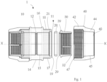
- the main body 10 has an outer body surface 14 and an inner body surface 15.
- the main body 10 defines a pipe insertion space extending in an axial direction, between an open end 11, i.e. the end where the pipe is inserted, and an inner radial rib 12 extending radially internally from the inner body surface 15.
- the inner radial rib 12 is provided to stop the pipe inserted in the main body 10.
- the nut 40 has also a second nut portion 44 extending axially between the first nut portion 42 and a nut free end 48.
- the second nut portion 44 is provided to extend axially away from the open end 11 of the main body.
- the grip ring 30 is a friction ring designed to maintain the pipe against pullout force due to internal pressure or external load.
- the grip ring 30 is extending axially and has an outer conical shape which is provided to deform when the nut 40 is threaded on the main body 10.
- the second nut portion 44 has a nut inner surface 45 having a corresponding conical shape, with a diameter decreasing from the nut threads 47 to the open end 48, designed to cooperate with the ring conical shape.
- the mechanical fitting of the present disclosure has a surface deformation of pipe no more than 0.5 %. This deformation is neglectable and is considered as a surface deformation, only, yet without deformation of the pipe itself.
- the inventors have machined a friction ring with a diameter 63 mm and a contact length of the 26.59 mm between the nut 40 and the ring 30.
- the surface roughness of the outer ring surface was measured to be 0,15 ⁇ m.
- the insertion force was measured to be1804 N.
- the insertion force is considered to be equivalent to the friction force.
- the pull out force is about 5000 N for an operating pressure of 10 bars, and 3000 N for an operating pressure of 6 bars, whilst the insertion force is independent of the operating pressure.
- the grip ring 30 may not be a full closed ring and can be an open ring instead, with one or more opening slots 37 provided to distribute the griming load of the grip ring 30.
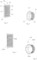
- longitudinal slots can extend from one axial end 31 or from the other axial end 32, as illustrated in figures 4 and 5 , where the friction ring 130 having longitudinal slots 138A extending from one axial end and longitudinal slot 138B extending from the other axial end. Having longitudinal slots extending from both axial ends of the grip ring 30 allows creating space to help relaxation of the material under load and generate less force on the nut.
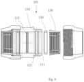
- a mechanical fitting 101 with the friction ring 130 is shown on Figure 6 .
- a joint 20 is provided inside a joint housing 21 in the main body.
- the joint 20 will deform against the main body in one side and against the rigid pipe on another side, thereby insuring the tightening function.
- the joint 20 can have an internal triangle shape, to facilitate the pipe insertion.
- the joint 20 also takes part at the friction.
- the joint is a rubber joint preferably made of reinforced polymer.
- the nut 40 is preferably made of polymer.
- Figure 6 shows a mechanical fitting 101 with the friction ring 130, having longitudinal slots extending from both axial ends.
- the mechanical fitting 101 has a main body 110 extending between an open end 111 and a pipe stop 112.
- a joint 120 is provided, in a joint housing 121, whose localisation in the fitting differs from the mechanical fitting of Figure 1 .
- the joint 20 is located at the open end 11 of the main body 10 and the joint 20 is pushed by the extension rib 29 of the grip ring 30, to deform the rubber to make water tightness.
- the joint 120 is not located at the open end but further inside the main body 101, somewhere between the open end 111 and the pipe stop 112. Therefore, there is no need for the grip ring 130 to push the joint 120, because water tightness can occur during the pipe insertion. There is enough interface between the pipe and the rubber 120. In turn, the grip ring 130 has not extension rib.
- Figures 7 and 8 show another embodiment of a mechanical 201 fitting allowing the connection of a pipe 2 (not shown on figure 8 ) according to another aspect of the present disclosure.
- the mechanical fitting 201 comprises a main body 210 for receiving the pipe 2 (visible on Figure 7 ).
- a nut 240 is provided to be mounted over the main body 210 when the pipe is inserted into the main body, to close the fitting after insertion of the pipe.
- the nut 240 is not provided over the entire main body 210 but only over a nut receiving part 218 of the main body 10 extending between the open end 211 and an outer radial projection 216 on the outer body surface 215.
- the outer radial projection 16 forms a stop for the nut 240.
- the nut receiving part 218 has external threads 217 extending between the outer radial projection 216 and the open end 211.
- the external threads 217 are provided for threading the nut 240 on the main body 10 when the pipe is inserted and positioned within the main body 10.
- the nut 240 has therefore corresponding nut threads 247.
- the outer radial projection 16 is axially spaced apart from the inner radial projection 12. With other words, not all of the pipe length inserted into the fitting 1 will be below the nut 40 and the pipe free end abutting against the inner radial projection 12 is not provided below the nut 40.
- the nut 240 is designed to house a grip ring 230.
- the grip ring 230 is illustrated on figures 9 and 10 .
- the grip ring 230 is a friction ring designed to maintain the pipe against pullout force due to internal pressure or external load.
- the grip ring 230 is extending axially.
- the nut 40 had an inner conical shape cooperation with the outer conical shape of the grip ring 30, in this aspect, the main body 210 has an inner conical shape to cooperate with the outer conical shape of the grip ring 230.
- the conical shape of the main body has a diameter decreasing from the open end 211 to the inside of the main body.
- the conical shape stops at an axial point located about below the radial projection 216.
- the conical shape helps closing the fitting on the pipe.
- the grip ring 30 under load closes itself around the pipe.
- the grip ring 230 has an outer ring surface 234 and an inner ring surface 235.
- the skilled person understands that the inner ring surface 235 defines an inner friction interface between the pipe and the grip ring 230, and the outer ring surface 234 defines an outer friction interface between the grip ring 30 and the mounting body 210.
- the grip ring are friction surfaces, and it is important to note that the pipe should not deform under the fixation force.
- the mechanical fitting 1 is designed to reduce the load on the pipe, to avoid that the pipe breaks under the load.
- the present disclosure proposes relying on friction.
- the pipe is brittle and can not withstand deformation. Therefore, it is not possible to rely on compression and deformation of the pipe for deforming the pipe and fixing the fitting, as was done with the mechanical fitting of the known prior art.
- internal circumferential recesses 233 extending radially inside the ring 30 are used to provide a rough surface between the pipe 2 and the friction ring 230.
- a rough surface instead of a smooth surface helps maintaining the pipe and preventing sliding or translation of the pipe with respect to the friction ring.
- the inner ring surface has an inner friction coefficient for defining an inner friction interface between the pipe and the grip ring
- the outer ring surface has an outer friction coefficient for defining an outer friction interface between the grip ring and one of the main body and the nut, and the inner friction coefficient is higher the outer friction coefficient
- the grip ring 230 has an outer radial projection 239, to abut against the open end 211 of the main body.
- a reinforcing element 262 is provided for the friction ring 230.
- the reinforcing element 262 is an open ring element.
- the open ring may be a metallic open ring, inserted inside the ring 230.
- the grip ring 30 has an outer projection 39 designed to abut against a flange 19 formed at the open end 11 of the main body 10.
- a joint 220 is provided inside a joint housing 221 in the main body.
- the joint 220 is best shown on figures 12 and 13 .
- the joint 220 can have an internal triangle shape, to facilitate the pipe insertion.
- the joint has a pipe contact surface 222 opposite a fitting contact surface 223 connected by a circular joining section 224.
- the pipe is pressed between the pipe and the fitting, with the pipe contact surface 222 and the fitting contact surface 223 being moved one towards the other.
- the shape of the joining surface 224 ensures tightness, when the joint is compressed.
- the joint 220 also takes part at the friction.
- the joint is a rubber joint preferably made of reinforced polymer.
- This technology has significant impact to replace solvent cement connection for CPVC, PVC, and PVC-U pipe.
- the grip rings 30, 130 do not deform the pipe 2.
- the mechanical fitting taking into account the friction coefficient and the required minimum contact surface for resisting the pull-out force, provides a well-defined contact both on the dimensions but also in order not to bring too much stress on the c-PVC.
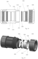
- Figures 14 and 15 show exploded views of another embodiment of a mechanical fitting 301 allowing the connection of a pipe 2 (not shown on the figures) according to another aspect of the present disclosure.
- the mechanical fitting 301 comprises a main body 310 for receiving the pipe.
- the main body 210 defines a pipe insertion space extending in an axial direction, between an open end 311, i.e. the end where the pipe is inserted, and an inner radial rib 312 extending radially internally from the inner body surface.
- the inner radial rib 312 is provided to stop the pipe inserted in the main body 310.
- a nut 340 is provided to be mounted over the main body when the pipe is inserted into the main body, to close the fitting after insertion of the pipe.
- the nut 340 is not provided over a nut receiving part 318 of the main body 210 extending between the open end and an outer radial projection 316 on the outer body surface.
- the outer radial projection 316 forms a stop for the nut 340.
- the nut receiving part 318 has external threads 317 extending between the outer radial projection 316 and the open end.
- the external threads 317 are provided for threading the nut on the main body when the pipe is inserted and positioned within the main body.
- the nut 240 has therefore corresponding nut threads 347.
- the grip ring 330 has longitudinal slots 338 to help to compensate the ovality of the rigid pipe.
- Longitudinal slots 338 give some flexibility to the ring, which is otherwise made of a rigid material. This helps distributing the load homogeneously along the pipe and avoid local concentration of the load.
- the reinforcing element 362 is provided with internal circumferential recesses 363 extending radially inside reinforcing element 362.
- the internal circumferential recesses 363 provides a rough surface between the pipe and the friction ring 330.
- a rough surface instead of a smooth surface helps maintaining the pipe and preventing sliding or translation of the pipe with respect to the friction ring.
- a joint 320 is provided inside a joint housing in the main body, which will deform against the main body on one side and against the rigid pipe on another side, thereby insuring the tightening function.
- the joint 320 also takes part at the friction.
- the joint is a rubber joint preferably made of reinforced polymer.
- the ring and the reinforcement part are combined into a single part, while part 230 will remain unchanged.
- This technology has significant impact to replace solvent cement connection for c-PVC, PVC, and PVC-U pipe.
- the mechanical fitting taking into account the friction coefficient and the required minimum contact surface for resisting the pull-out force, provides a well-defined contact both on the dimensions but also in order not to bring too much stress on the pipe material, such as PVC based material.
Landscapes
- Engineering & Computer Science (AREA)
- General Engineering & Computer Science (AREA)
- Mechanical Engineering (AREA)
- Mutual Connection Of Rods And Tubes (AREA)
Applications Claiming Priority (1)
| Application Number | Priority Date | Filing Date | Title |
|---|---|---|---|
| FR2315094A FR3157505A1 (fr) | 2023-12-22 | 2023-12-22 | Raccords mécaniques pour cpvc |
Publications (1)
| Publication Number | Publication Date |
|---|---|
| EP4575291A1 true EP4575291A1 (fr) | 2025-06-25 |
Family
ID=91247811
Family Applications (1)
| Application Number | Title | Priority Date | Filing Date |
|---|---|---|---|
| EP24221067.2A Pending EP4575291A1 (fr) | 2023-12-22 | 2024-12-18 | Raccords mécaniques pour matériau à base de pvc |
Country Status (5)
| Country | Link |
|---|---|
| US (1) | US20250207708A1 (fr) |
| EP (1) | EP4575291A1 (fr) |
| AU (1) | AU2024287131A1 (fr) |
| CA (1) | CA3260498A1 (fr) |
| FR (1) | FR3157505A1 (fr) |
Citations (4)
| Publication number | Priority date | Publication date | Assignee | Title |
|---|---|---|---|---|
| DE2550389A1 (de) * | 1974-11-20 | 1976-08-12 | Paragon Plastics Ltd | Rohrverbinder |
| FR2315094A1 (fr) | 1975-06-19 | 1977-01-14 | Schneider Co Inc J R | Determinations de la concentration en additif bactericide d'un liquide |
| JPH09229258A (ja) * | 1996-02-23 | 1997-09-05 | Mitsubishi Kagaku Sanshi Kk | プラスチック管の継手装置 |
| DE60302723T2 (de) * | 2002-07-10 | 2006-06-14 | Masafumi Minami | Rohrverbindungsvorrichtung |
Family Cites Families (4)
| Publication number | Priority date | Publication date | Assignee | Title |
|---|---|---|---|---|
| FR1134192A (fr) * | 1954-09-22 | 1957-04-08 | Sun Engineering Richmond Ltd | Joint d'accouplement pour tubes ou tuyaux |
| GB1072872A (en) * | 1963-02-05 | 1967-06-21 | Mannin Eng Ltd | Improvements in or relating to pipe couplings |
| MY191096A (en) * | 2018-02-14 | 2022-05-30 | Norma China Co Ltd | Compression fitting with a securing means |
| US20240117905A1 (en) * | 2022-10-11 | 2024-04-11 | The Ford Meter Box Company, Inc. | Wide Range Coupling Assembly |
-
2023
- 2023-12-22 FR FR2315094A patent/FR3157505A1/fr active Pending
-
2024
- 2024-12-18 CA CA3260498A patent/CA3260498A1/en active Pending
- 2024-12-18 EP EP24221067.2A patent/EP4575291A1/fr active Pending
- 2024-12-21 AU AU2024287131A patent/AU2024287131A1/en active Pending
- 2024-12-22 US US18/991,578 patent/US20250207708A1/en active Pending
Patent Citations (4)
| Publication number | Priority date | Publication date | Assignee | Title |
|---|---|---|---|---|
| DE2550389A1 (de) * | 1974-11-20 | 1976-08-12 | Paragon Plastics Ltd | Rohrverbinder |
| FR2315094A1 (fr) | 1975-06-19 | 1977-01-14 | Schneider Co Inc J R | Determinations de la concentration en additif bactericide d'un liquide |
| JPH09229258A (ja) * | 1996-02-23 | 1997-09-05 | Mitsubishi Kagaku Sanshi Kk | プラスチック管の継手装置 |
| DE60302723T2 (de) * | 2002-07-10 | 2006-06-14 | Masafumi Minami | Rohrverbindungsvorrichtung |
Also Published As
| Publication number | Publication date |
|---|---|
| FR3157505A1 (fr) | 2025-06-27 |
| US20250207708A1 (en) | 2025-06-26 |
| AU2024287131A1 (en) | 2025-07-10 |
| CA3260498A1 (en) | 2025-10-31 |
Similar Documents
| Publication | Publication Date | Title |
|---|---|---|
| EP2564104B1 (fr) | Raccords pour tubes à haute pression et outils de préparation de la face terminale | |
| EP2470817B1 (fr) | Raccord à presser à fonction d anneau de prise | |
| CN103201551B (zh) | 具有套管的推动连接管接头 | |
| US8308201B2 (en) | Crimp fitting for corrugated stainless steel tubing | |
| US8770630B2 (en) | Hose connecting method and connector arrangement | |
| US20100201124A1 (en) | Fitting with bushing for corrugated stainless steel tubing | |
| US20100090459A1 (en) | Quick actuating fitting for corrugated stainless steel tubing | |
| WO2012018576A1 (fr) | Pousseur à axe unique pour raccorder un raccord de conduit | |
| US9651177B2 (en) | Coupling connection for corrugated pipes | |
| US20100181760A1 (en) | Snap-fit fitting for corrugated stainless steel tubing | |
| KR20060113929A (ko) | 금속 파이프 및 배관용 이음쇠 | |
| EP4194732A1 (fr) | Raccord avec anneau de préhension | |
| EP0531068A2 (fr) | Raccord de tuyaux | |
| EP4575291A1 (fr) | Raccords mécaniques pour matériau à base de pvc | |
| EP4162187B1 (fr) | Système d'accouplement hydraulique | |
| WO2002042672A2 (fr) | Raccords de tuyau ou de conduit ou raccords d'extremite | |
| EP4575295A1 (fr) | Raccords mécaniques | |
| EP4614046A2 (fr) | Raccord mécanique et méthode d'assemblage | |
| EP1605196A1 (fr) | Raccord pour tuyaux à surface ondulée | |
| EP3992509B1 (fr) | Raccord à pression et procédé de raccordement d'un raccord à pression avec un extrémité de tuyau | |
| ITBS20030054U1 (it) | Raccordo di giunzione per tubi multistrato | |
| LU102157B1 (en) | Press fitting with axial push | |
| JPH05506080A (ja) | ホースを接続具に取り付ける装置 |
Legal Events
| Date | Code | Title | Description |
|---|---|---|---|
| PUAI | Public reference made under article 153(3) epc to a published international application that has entered the european phase |
Free format text: ORIGINAL CODE: 0009012 |
|
| STAA | Information on the status of an ep patent application or granted ep patent |
Free format text: STATUS: THE APPLICATION HAS BEEN PUBLISHED |
|
| AK | Designated contracting states |
Kind code of ref document: A1 Designated state(s): AL AT BE BG CH CY CZ DE DK EE ES FI FR GB GR HR HU IE IS IT LI LT LU LV MC ME MK MT NL NO PL PT RO RS SE SI SK SM TR |
|
| STAA | Information on the status of an ep patent application or granted ep patent |
Free format text: STATUS: REQUEST FOR EXAMINATION WAS MADE |
|
| 17P | Request for examination filed |
Effective date: 20260102 |