EP4575295A1 - Raccords mécaniques - Google Patents
Raccords mécaniques Download PDFInfo
- Publication number
- EP4575295A1 EP4575295A1 EP24219958.6A EP24219958A EP4575295A1 EP 4575295 A1 EP4575295 A1 EP 4575295A1 EP 24219958 A EP24219958 A EP 24219958A EP 4575295 A1 EP4575295 A1 EP 4575295A1
- Authority
- EP
- European Patent Office
- Prior art keywords
- pipe
- ring
- fitting
- crimping
- main
- Prior art date
- Legal status (The legal status is an assumption and is not a legal conclusion. Google has not performed a legal analysis and makes no representation as to the accuracy of the status listed.)
- Pending
Links
Images


Classifications
-
- F—MECHANICAL ENGINEERING; LIGHTING; HEATING; WEAPONS; BLASTING
- F16—ENGINEERING ELEMENTS AND UNITS; GENERAL MEASURES FOR PRODUCING AND MAINTAINING EFFECTIVE FUNCTIONING OF MACHINES OR INSTALLATIONS; THERMAL INSULATION IN GENERAL
- F16L—PIPES; JOINTS OR FITTINGS FOR PIPES; SUPPORTS FOR PIPES, CABLES OR PROTECTIVE TUBING; MEANS FOR THERMAL INSULATION IN GENERAL
- F16L33/00—Arrangements for connecting hoses to rigid members; Rigid hose-connectors, i.e. single members engaging both hoses
- F16L33/02—Hose-clips
- F16L33/025—Hose-clips tightened by deforming radially extending loops or folds
-
- F—MECHANICAL ENGINEERING; LIGHTING; HEATING; WEAPONS; BLASTING
- F16—ENGINEERING ELEMENTS AND UNITS; GENERAL MEASURES FOR PRODUCING AND MAINTAINING EFFECTIVE FUNCTIONING OF MACHINES OR INSTALLATIONS; THERMAL INSULATION IN GENERAL
- F16L—PIPES; JOINTS OR FITTINGS FOR PIPES; SUPPORTS FOR PIPES, CABLES OR PROTECTIVE TUBING; MEANS FOR THERMAL INSULATION IN GENERAL
- F16L49/00—Connecting arrangements, e.g. joints, specially adapted for pipes of brittle material, e.g. glass, earthenware
- F16L49/06—Joints in which sealing surfaces are pressed together by means of a member, e.g. swivel nut, screwed on, or into, one of the joint parts
-
- F—MECHANICAL ENGINEERING; LIGHTING; HEATING; WEAPONS; BLASTING
- F16—ENGINEERING ELEMENTS AND UNITS; GENERAL MEASURES FOR PRODUCING AND MAINTAINING EFFECTIVE FUNCTIONING OF MACHINES OR INSTALLATIONS; THERMAL INSULATION IN GENERAL
- F16L—PIPES; JOINTS OR FITTINGS FOR PIPES; SUPPORTS FOR PIPES, CABLES OR PROTECTIVE TUBING; MEANS FOR THERMAL INSULATION IN GENERAL
- F16L47/00—Connecting arrangements or other fittings specially adapted to be made of plastics or to be used with pipes made of plastics
- F16L47/16—Screw-threaded joints
Definitions
- the present invention relates to the field of mechanical fittings.
- the present invention relates to a mechanical fitting for connecting pipes or for attaching a pipe, an assembly of a mechanical fitting and a pipe, and a method of assembly of a mechanical fitting and a pipe.
- Crimping fittings also called press fittings, which can connect pipes by compression and deformation using one or two sleeves, are well known in the field of tubing, piping and line system installation, for example, water, gas or heating.
- Press fittings are used to connect not only metal but also plastic or composite metal-plastic pipes. They are used to connect appropriately arranged sections of pipe, with their connecting pieces being inserted into the ends of the pipes to be connected, where they are then deformed or crimped or pressed. They are fastened in certain zones, e.g. using press sleeves on the pieces by using so-called system compression tools that usually have interchangeable pressing jaws.
- the tube, pipe, or conduit systems are assembled in several steps: first the pipes are inserted into a fitting, and then the fitting is crimped to guarantee good mechanical strength and a leaktight installation.
- the compression is essentially a pressure on the fitting sleeve - also referred to as a press sleeve - which causes the deformation or shaping of the fitting to the pipe which is inserted into it.
- the pressure is usually applied to the fitting using a press jaw acting as a compression tool. These press jaws apply radial pressure to the fitting material in order to bring about an interaction with the surface of the pipe(s)/pipe(s) to be connected, thus achieving a reliable connection and a reliable seal.
- c-PVC exhibits different properties and is more brittle than other materials and c-PVC is more fragile over time.
- One object of the present disclosure is to propose a mechanical fitting that allows the connection of c-PVC, PVC, and PVC-U piping systems for hot and cold-water installations, hot and cold pressurized applications.
- the present invention proposes a mechanical fitting for connecting pipes or for attaching a pipe, comprising a main fitting body extending axially between a body end and an open end defining an insertion space for a pipe, designed to close over a pipe, and a crimping ring mounted over the main fitting body for tightening the main fitting body over the pipe.
- the crimping ring comprises a ring body in a form of an open ring connected by a crimping ear projecting radially outwardly from the ring body, the crimping ear being deformable to close the crimping ring over the pipe during the crimping process.
- the mechanical fitting has an anti-deformation arrangement for preventing deformation of the pipe inserted therein during crimping.
- the present invention proposes a mechanical fitting designed to use friction instead of compression for ensuring a connection between the mechanical fitting and a pipe inserted therein.
- a mechanical fitting relying on friction aims at not deforming the pipe during assembly, but at creating a friction interface at the interface of the pipe and of the grip ring, capable of withstanding the pull-out force under operation. Therefore, anti-deformation arrangement for preventing deformation of the pipe inserted therein during crimping.
- the deformation of the pipe remains within the ovality of the pipe.
- Ovality of the pipe is defined as the difference between maximum and minimum diameter of the pipe over its length. For example, for a c-PVC pipe with a nominal diameter of 63 mm, the ovality is of about 0.1 to 0.15 mm depending on the condition of storage of pipe. Thus, the maximum diameter could be 63.15 mm.
- the inner surface is a friction surface provided with recesses, in particular circumferential recesses extending radially inside the main fitting body and forming a friction surface over a contact length as part of the anti-deformation arrangement. These circumferential recesses help connect and maintain not only smooth but also rough surface pipes.
- the fitting body has at least one axial slot, the anti-deformation arrangement comprising the at least one axial slot.
- the axial slot of the fitting body allows radial movement of the main fitting body.
- the main fitting body may deform against the pipe during crimping and adapt to the form of the tube which may have a cross section which is not perfectly round, due to ovality of the pipe. This avoids concentration of forces on the pipe by allowing good repartition of the load on the pipe.
- the fitting body is provided with a reinforcing element below the ring reception surface, such as a metallic open ring, in particular located between the main fitting body and the pipe when assembled.
- a reinforcing element below the ring reception surface, such as a metallic open ring, in particular located between the main fitting body and the pipe when assembled.
- the metallic ring is provided to avoid deformation and collapsing the pipe.
- the inner surface has circumferential recesses extending radially inside the main fitting body, and the inner surface forms a friction surface over a contact length as part of the anti-deformation arrangement. This helps creating a friction interface for maintaining the pipe within the mechanical fitting.
- the circumferential recesses are designed to create fictional resistance against any pullout force. The are located inside the main body, they create frictional resistance outside the pipe surface.
- an outer sleeve is provided over the compression ring, to maintain axially the crimping ring on the main fitting body.
- the crimping ring is provided over a ring reception part of the main body extending between the open end and an outer radial projection on an outer body surface of the main body.
- a ring reception part allows maintaining the crimping ring in place. This helps preassemble the crimping ring with the fitting body and maintain the crimping ring on the reception part even before crimping, thanks to radial projection and the anti-deformation arrangement.
- the crimping ring can be directly mounted and fixed on the main fitting body, there is no need for additional fixation pieces.
- the main body has an inner radial rib at its body end opposite the free end, and wherein the outer radial projection is axially spaced apart from the inner radial rib.
- the inner radial rib allows a user to insert the pipe correctly without issues of over-inserting or under-inserting the pipe. Rib acts as a stopper, stopping the pipe at the right insertion distance. The pipe insertion distance is required for reliable connection.
- the joint is designed to provide sealing joint during pipe insertion without any post-extra compression of joint after the pipe insertion.
- the main challenge is to maximize sealing, in particular to maximize operating pressure, whilst at the same time minimizing the pipe insertion force. This allows an installer inserting the pipe into the fitting easily without requiring heavy instrument for insertion.
- the joint has a different cross-section profile than a O-ring, and the joint works when the pipe is inserted into the main body even without crimping.
- the joint is positioned outside of the pipe surface. O-ring cannot be used in the friction fitting, because the crimping process will not deform the pipe and joint. Of course, the joint can become tightened during the pipe insertion process.
- the crimping ring after closing of the crimping ring, is provided over a ring reception part of the main fitting body extending between the open end and an outer radial projection on an outer body surface of the main body, and/or the outer pipe diameter is reduced by maximum 0.5 %.
- a diameter reduction of 0.5 % remains on the outside surface of the pipe to create the frictional contact surface, which means that the pipe is not deformed by the crimping, there is no diminution of the cross-flow, hence the inner pipe diameter is not reduced.
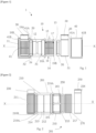
- Figure 1 show a mechanical fitting 1 allowing the connection of a tube (not shown on figure 1 ) according to one aspect of the present invention.
- the tube may be for example a pipe for/in a piping system for fluid installations inside buildings.
- the crimping ring 30 comprises a ring body 31 in a form of an open ring connected by a crimping ear 36 projecting radially outwardly from the ring body 31.
- a crimping ear 36 projecting radially outwardly from the ring body 31.
- there is one crimping ear but it is possible to have two or more crimping ears.
- the crimping ear 36 is deformed and the annular ends of the open ring body move towards each other during the crimping process to close the ring body 31.
- PVC polyvinyl styrene
- PVC-U polyvinyl styrene
- the crimping ring 30 is designed so that the total closing of crimping ear 36 does not result in the deformation of the pipe inserted therein.
- the present disclosure proposes relying on friction.
- the fitting is designed to allow a certain degree of deformation of the fitting such that the resulting biasing is suitable to provide the needed friction though without being such that deformation would be induced in the tube or pipe to be attached.
- crimping fittings of the prior art, for PE pipe are based on deforming the pipe and reducing the outer diameter in order to maintain the pipe against pullout force generated due to internal operating pressure.
- the inventors have measured deformation of the pipe with different existing designs. They measured a reduction of the pipe diameter from 32 to 30.6 mm, which is equivalent to 1.4 mm of pipe thickness.
- the pipe thickness is reduced by 1.4 mm, which is equivalent to 46% of pipe wall deformation or thickness reduction.
- PVC based pipes such as PVC pipes, c-PVC pipes or PVC-U pipes
- PVC based pipes are brittle and cannot withstand deformation. Therefore, it is not possible to rely on compression and deformation of the pipe for deforming the pipe and fixing the fitting, as was done with the mechanical fitting of the known prior art.
- c-PVC focus is made in the present disclosure on c-PVC as this is the more resistant material under high pressure and temperature. The brittleness is however similar for all PVC based materials.
- the mechanical fitting of the present disclosure has a deformation of pipe no more than 0.5 %. This deformation is neglectable and is considered as a surface deformation, only, yet without deformation of the pipe itself.
- the friction between the pipe and the main fitting body is optimized to be greater than the applied pullout force on the pipe. Minimal frictional force is required to maintain the pipe against the pull-out force due to internal pressure and external force.
- the pull-out force on the pipe is typically function of the operating pressure and of the diameter of the pipe.
- the inner surface 15 of the main fitting body 10 defines a friction surface to allow good grip of the pipe.
- L represent the friction contact length, hence the contact surface area between the pipe and the fitting body
- m is mass, and hence represents also the load due to internal pressure Therefore, a minimum length of contact is required to be considered to create a frictional force to maintain pipe against pullout force, and the crimping area should be determined to ensure acceptable stress distribution on the pipe.
- L DN 4 ⁇ stress ⁇ P d
- Pd the pressure
- L the axial contact length
- DN the nominal diameter of the pipe
- the design stress generated on the pipe c-PVC pipe all class Type II should be less or egal to 2.86 MPa.
- a fitting with diameter of 63 mm should resist a pullout force generated due to a pressure of 4.7 MPa.
- 25. 88 mm is the minimum length of the surface to not generate a load more than 2.86 MPa on the pipe.
- the minimum axial contact length is required to be considered to create frictional force to maintain pipe against pullout force.
- the inner outer envelope surface of the main fitting body 10 has a body diameter equal to or greater than the outer diameter of the pipe, or at least gratis to the diameter of the pipe taking account of the ovality of the pipe, with a reduction of pipe diameter of less than 0.5% after crimping.
- the design of the crimping ring 30 with respect to the pipe dimension is a first anti deformation feature.
- the internal radial recess 17 allow homogeneous distribution of the crimping load on the pipe.
- the crimping ring 30 is mounted on the main fitting body 10, on a ring reception part 18 of the outer surface 14 of the main fitting body 10.
- the ring reception part 18 is formed by a recess delimited by a first radial projection 19A and a second projection 19B projecting away from the outer surface of the main fitting body.
- the second projection 19B is located at the open end 11 of the main fitting body.
- the distance between the first radial projection 19A and a second radial projection 19B corresponds to the width of the crimping ring 30.
- the crimping ring 30 is axially fixed on the main fitting body and can be freely rotatable around the main fitting body. This is advantageous for the user as it allows the positioning of the fitting and the insertion of the tube in any position, and rotating after the crimping ring in a position in which it is easier for the user to crimp the fitting.
- An outer sleeve 40 is provided to cover the crimping ring 30 and protect the crimping ring 30.
- the outer sleeve 40 with a first inward radial projection 41A and a second inward radial projection 41B to fix the outer sleeve 40 on the main fitting body 10.
- the first inward radial projection 41A and the second inward radial projection 41B can be clipped over the first radial projection 19A and a second radial projection 19B.
- the crimping ring 30 is maintained in axial position in the ring reception space 18 by the first and second radial projections 19A, 19B.
- the outer sleeve 40 has only a cover function. As will be detailed with reference to figure 7 , the outer sleeve may have the function of holding the compression ring in the ring reception space.
- a joint 50 is provided inside a joint housing 51 in the main body.
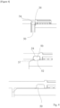
- the joint 50 is best shown on figures 4 to 6 .
- the joint 50 has an interface 52 with the pipe and an interface 54 with the main body 10.
- the joint 50 will deform against the main body in one side and against the rigid pipe on another side, thereby insuring the tightening function.
- the joint 50 also takes part at the friction.
- the joint is a rubber joint.
- the joint is not a O ring joint but is designed to interact and deform around the pipe.
- the joint is a banana shape type joint.
- the joint 50 has an internal triangle shape for the insertion of the pipe, with an insertion surface 56 facing the open end of the fitting, hence the pipe when the pipe is inserted.
- the insertion surface 56 facilitates the insertion of the pipe, as can be seen on Figure 4 , before pipe insertion (upper part), during pipe insertion (middle part) and after pipe insertion (lower part).
- the joint 50 On the rear side of the joint axially opposite to the insertion surface, the joint 50 has a rear surface 57 having a step like shape. This surface creates an interface between the pipe inserted in the fitting and the joint which creates the water tightness.
- the step like rear surface 57 gives room for the joint and thereby allows deformation of the joint around the pipe to create water tightness.
- the deformed joint is shown on Figure 4 , after insertion.
- Figure 2 shows a mechanical fitting 201 allowing the connection of a tube (not shown on figure 1 ) according to another aspect of the present invention.
- the tube may be for example a pipe for/in a piping system for fluid installations inside buildings.
- the main fitting body 210 has an outer body surface 214 and an inner body surface 215.
- the main fitting body 210 defines a pipe insertion space extending in an axial direction X-X, between an open end 211, i.e. the end where the pipe is inserted, and an inner radial rib 212 extending radially internally from the inner body surface 215.
- the inner radial rib 212 is provided to stop the pipe inserted in the main fitting body 210.
- a crimping ring 230 is provided over the main fitting body 210, over a ring receiving part 218 of the main fitting body 210 extending between the open end 211 and an outer radial projection 219A extending radially away from the outer body surface 214.
- the crimping ring 230 comprises a ring body in a form of an open ring connected by a crimping ear 236 projecting radially outwardly from the ring body.
- the crimping ear 236 is deformed and the annular ends of the open ring body move towards each other during the crimping process to close the ring body.
- the crimping ring 230 is designed so that the total closing of crimping ear 236 does not result in the deformation of the pipe inserted therein.
- the inner surface 215 of the main fitting body 210 defines a friction surface to allow good grip of the pipe.
- the pipe is brittle and cannot withstand deformation. Therefore, it is not possible to rely on compression and deformation of the pipe for deforming the pipe and fixing the fitting, as was done with the mechanical fitting of the known prior art. Instead, the crimping fitting must rely on friction because of the c-PVC material. C-PVC is brittle and will only break during a crimping process of a prior art.
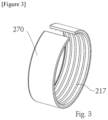
- the reinforcing element 270 is an open ring, which can be metallic.
- the friction surface is the inner surface of the reinforcing element 270, provided for maintaining the pipe and preventing sliding or translation of the pipe with respect to the mechanical fitting.
- the pipe should not slide with respect to the mechanical fitting, during tightening of the fitting and later on.
- the inner outer envelope surface of the main fitting body 10, with the reinforcing element 270 has a body diameter equal to or greater than the outer diameter of the pipe.
- the minimum axial contact length between the reinforcing element 270 and the pipe is 25, 88 mm.
- the main fitting body When fully closed, for a tube with a diameter of 63mm, the main fitting body has an inner diameter of max 63mm.
- the design of the crimping ring with the right dimension when fully closed with respect to the pipe dimension is anti-deformation feature.
- the main fitting body 210 is provided with at least one axial slot 261, which allow radial movement of the main fitting body 210.
- the reinforcing element 270 is also an open ring. During crimping, the main fitting body 10, and the reinforcing element, may deform against the pipe during crimping and adapt to the form of the pipe which may have a cross section which is not perfectly round. The axial slot further prevents deformation of the pipe if the main fitting body shape does not match perfectly the pipe shape.
- the crimping ring 230 is mounted on the main fitting body 210, on a ring reception part 218 of the outer surface 214 of the main fitting body 210.
- the ring reception part 218 is delimited by a first radial projection 219A and a second projection 219B projecting away from the outer surface of the main fitting body.
- the second projection 219B is located at the open end 211 of the main fitting body. The distance between the first radial projection 219A and a second radial projection 219B corresponds to the width of the crimping ring 230.
- the crimping ring 230 is axially fixed on the main fitting body and can be freely rotatable around the main fitting body. This is advantageous for the user as it allows the positioning of the fitting and the insertion of the tube in any position, and rotating after the crimping ring in a position in which it is easier for the user to crimp the fitting.
- a joint 250 is provided inside a joint housing 251 in the main body.
- the joint 250 is similar to the joint 50 of the mechanical fitting 1 of figure 1 .
- Figure 7 shows a mechanical fitting 301 allowing the connection of a tube (not shown on figure 1 ) according to another aspect of the present invention
- Figure 8 shows the mechanical fitting 301 with a tube according to another aspect of the present invention.
- the tube may be for example a pipe for/in a piping system for fluid installations inside buildings.
- the main fitting body 310 has an outer body surface 314 and an inner body surface 315.
- the main fitting body 310 defines a pipe insertion space extending in an axial direction X-X, between an open end 311, i.e. the end where the pipe is inserted, and an inner radial rib 312 extending radially internally from the inner body surface 315.
- the inner radial rib 312 is provided to stop the pipe inserted in the main fitting body 310.
- a crimping ring 330 is provided over the main fitting body 310, over a ring receiving part 318 of the main fitting body 310 extending between the open end 311 and an outer radial projection 319A extending radially away from the outer body surface 314.
- the crimping ring 330 comprises a ring body in a form of an open ring connected by a crimping ear 36 projecting radially outwardly from the ring body. Similar to the crimping rings 30, 230 of the mechanical fittings of Figures 1 and 2 , the crimping ring 330 is designed so that the total closing of crimping ear 336 does not result in the deformation of the pipe inserted therein. When the crimping ring 330 is closed, the inner surface 315 of the main fitting body 310 defines a friction surface to allow good grip of the pipe over a friction length, as for the mechanical fittings of figures 1 and 2 .
- the inner outer envelope surface of the main fitting body 310, with the reinforcing element has a body diameter equal to or greater than the outer diameter of the pipe.
- the crimping ring is configured so that, when fully closed, For example, for a tube with a diameter of 63 mm, the ear is designed so that, once fully closed, the main fitting body has an inner diameter reduced by maximum 2%, preferably maximum 1%, most preferably maximum 0.5%.
- the design of the crimping ring with the right dimension when fully closed with respect to the pipe dimension is a first anti deformation feature.
- the main fitting body 310 is provided with at least one axial slot 361, which allow radial movement of the main fitting body 310.
- the main fitting body 10 may deform against the pipe during crimping and adapt to the form of the tube which may have a cross section which is not perfectly round.
- the axial slot further prevents deformation of the pipe if the main fitting body shape does not match perfectly the pipe shape.
- the axial slots are another anti-deformation element.
- the crimping ring 330 is mounted on the main fitting body 310, on a ring reception part 318 of the outer surface 315 of the main fitting body 310.
- the ring reception part 318 is delimited by a first radial projection 319A, but, similar to the mechanical fitting of fig. 2 , there is no or a little second projection located at the open end of the main fitting body to maintain the crimping ring axially in/on the ring reception part 318.
- an outer sleeve 340 with a first inward radial projection 341A and a second inward radial projection 341B to maintain the crimping ring 330 in place at the axial position before crimping.
- the second inward radial projection 341B is provided to abut against the axial outer wall of the open end 311, whilst the first inward radial projection is provided to abut against the axial outer wall of the first radial projection of the main fitting body.
- the outer sleeve 340 is placed over the crimping ring 330, in engagement with the main fitting body, thereby maintain the crimping ring on the main fitting body.
- a joint housing 351 for hosting a joint 350 is provided axially between the inner radial projection 312 and the ring reception part 318, in particular below at an axial position adjacent to and inwardly from the outer radial projection 319A.
- the rubber socket will compress the rigid pipe and maintained against pullout force, it allows a homogeneous distribution of the crimping load on the pipe, it compensate also the ovality of the rigid pipe to a void local stress. At the same time the deformed rubber will insure water tightening.
- the joint 350 has an internal triangle shape.
- the outer radial projection 19A, 219A, 319A is axially spaced apart from the inner radial projection 12, 212, 312.
- the pipe free end abutting against the inner radial projection 12 is not provided below the crimping ring.
- not all of the pipe length inserted in the main fitting body is covered by the crimping ring, but not the entire length. This allows taking account of the fact that the end surface of the pipe may not be straight, for example the user may cut the pipe on site and the cut-out can be slanted. By leaving some space between the insertion end of the pipe an the crimping ring, it is ensure that the slanted part is not below the crimp ring which would otherwise alter the fitting performance.
- This technology has significant impact to replace solvent cement connection for CPVC, PVC, and PVC-U pipe.
- the mechanical fitting taking into account the friction coefficient and the required minimum contact surface for resisting the pull-out force, provides a well-defined contact both on the dimensions but also in order not to bring too much stress on the PVC, c-PVC, PVC-U.
Landscapes
- Engineering & Computer Science (AREA)
- General Engineering & Computer Science (AREA)
- Mechanical Engineering (AREA)
- Quick-Acting Or Multi-Walled Pipe Joints (AREA)
- Joints With Sleeves (AREA)
- Mutual Connection Of Rods And Tubes (AREA)
Applications Claiming Priority (1)
| Application Number | Priority Date | Filing Date | Title |
|---|---|---|---|
| FR2315057A FR3157506A1 (fr) | 2023-12-22 | 2023-12-22 | Raccords mécaniques pour cpvc |
Publications (1)
| Publication Number | Publication Date |
|---|---|
| EP4575295A1 true EP4575295A1 (fr) | 2025-06-25 |
Family
ID=90971811
Family Applications (1)
| Application Number | Title | Priority Date | Filing Date |
|---|---|---|---|
| EP24219958.6A Pending EP4575295A1 (fr) | 2023-12-22 | 2024-12-13 | Raccords mécaniques |
Country Status (4)
| Country | Link |
|---|---|
| US (1) | US20250207709A1 (fr) |
| EP (1) | EP4575295A1 (fr) |
| CA (1) | CA3260495A1 (fr) |
| FR (1) | FR3157506A1 (fr) |
Citations (5)
| Publication number | Priority date | Publication date | Assignee | Title |
|---|---|---|---|---|
| FR2315057A1 (fr) | 1975-06-17 | 1977-01-14 | Gym Dandy Inc | Crochet de support a bras transversal |
| EP0098237B1 (fr) * | 1982-06-29 | 1986-11-05 | MANNESMANN Aktiengesellschaft | Raccord démontable pour bouts de tuyau lisses |
| US20050161941A1 (en) * | 2004-01-23 | 2005-07-28 | Poll Steven A. | Compression clamp |
| WO2015197248A1 (fr) * | 2014-06-25 | 2015-12-30 | Geberit International Ag | Ensemble collier de serrage |
| EP2757299B1 (fr) * | 2011-03-11 | 2021-08-25 | Geberit International AG | Dispositif de serrage de tuyau |
-
2023
- 2023-12-22 FR FR2315057A patent/FR3157506A1/fr active Pending
-
2024
- 2024-12-13 EP EP24219958.6A patent/EP4575295A1/fr active Pending
- 2024-12-17 CA CA3260495A patent/CA3260495A1/en active Pending
- 2024-12-22 US US18/991,580 patent/US20250207709A1/en active Pending
Patent Citations (5)
| Publication number | Priority date | Publication date | Assignee | Title |
|---|---|---|---|---|
| FR2315057A1 (fr) | 1975-06-17 | 1977-01-14 | Gym Dandy Inc | Crochet de support a bras transversal |
| EP0098237B1 (fr) * | 1982-06-29 | 1986-11-05 | MANNESMANN Aktiengesellschaft | Raccord démontable pour bouts de tuyau lisses |
| US20050161941A1 (en) * | 2004-01-23 | 2005-07-28 | Poll Steven A. | Compression clamp |
| EP2757299B1 (fr) * | 2011-03-11 | 2021-08-25 | Geberit International AG | Dispositif de serrage de tuyau |
| WO2015197248A1 (fr) * | 2014-06-25 | 2015-12-30 | Geberit International Ag | Ensemble collier de serrage |
Also Published As
| Publication number | Publication date |
|---|---|
| US20250207709A1 (en) | 2025-06-26 |
| FR3157506A1 (fr) | 2025-06-27 |
| CA3260495A1 (en) | 2025-10-31 |
Similar Documents
| Publication | Publication Date | Title |
|---|---|---|
| RU2342591C1 (ru) | Вставной соединитель (варианты) | |
| CN103201551B (zh) | 具有套管的推动连接管接头 | |
| CA2728598C (fr) | Dispositif de fixation d'un raccord de conduite de fluide | |
| CA2514923C (fr) | Ajustement inserable pour tubes ondules | |
| US20100201124A1 (en) | Fitting with bushing for corrugated stainless steel tubing | |
| US20100181760A1 (en) | Snap-fit fitting for corrugated stainless steel tubing | |
| US9651177B2 (en) | Coupling connection for corrugated pipes | |
| US7726702B2 (en) | Flange connection for pipe | |
| RU2564156C2 (ru) | Фиттинг с фланцами для использования с системой герметизации труб | |
| EP0531068A2 (fr) | Raccord de tuyaux | |
| CA2829660C (fr) | Raccord de dispositif comportant un ecrou de compression avec un dispositif de retenue | |
| GB2431209A (en) | Pipe insert for multi-layered pipe | |
| EP4575295A1 (fr) | Raccords mécaniques | |
| EP3660376B1 (fr) | Joint de tuyau et structure de joint de tuyau | |
| WO2012064725A2 (fr) | Manchon | |
| EP4575291A1 (fr) | Raccords mécaniques pour matériau à base de pvc | |
| US20250283560A1 (en) | Mechanical Fitting | |
| EP3992509B1 (fr) | Raccord à pression et procédé de raccordement d'un raccord à pression avec un extrémité de tuyau | |
| IE53290B1 (en) | Spigot and socket connections | |
| CN116635168A (zh) | 压接管件装置 | |
| LU102157B1 (en) | Press fitting with axial push | |
| LU500410B1 (en) | Compression fitting | |
| US20250162108A1 (en) | Clamping Ring for a Fitting and Fitting with a Clamping Ring | |
| GB2630716A (en) | Pipe fitting | |
| GB2599164A (en) | Pipe fitting |
Legal Events
| Date | Code | Title | Description |
|---|---|---|---|
| PUAI | Public reference made under article 153(3) epc to a published international application that has entered the european phase |
Free format text: ORIGINAL CODE: 0009012 |
|
| STAA | Information on the status of an ep patent application or granted ep patent |
Free format text: STATUS: THE APPLICATION HAS BEEN PUBLISHED |
|
| AK | Designated contracting states |
Kind code of ref document: A1 Designated state(s): AL AT BE BG CH CY CZ DE DK EE ES FI FR GB GR HR HU IE IS IT LI LT LU LV MC ME MK MT NL NO PL PT RO RS SE SI SK SM TR |
|
| STAA | Information on the status of an ep patent application or granted ep patent |
Free format text: STATUS: REQUEST FOR EXAMINATION WAS MADE |
|
| 17P | Request for examination filed |
Effective date: 20260102 |