EP4575353A1 - Circuit de refroidissement de pompe à chaleur et pompe à chaleur - Google Patents
Circuit de refroidissement de pompe à chaleur et pompe à chaleur Download PDFInfo
- Publication number
- EP4575353A1 EP4575353A1 EP24215450.8A EP24215450A EP4575353A1 EP 4575353 A1 EP4575353 A1 EP 4575353A1 EP 24215450 A EP24215450 A EP 24215450A EP 4575353 A1 EP4575353 A1 EP 4575353A1
- Authority
- EP
- European Patent Office
- Prior art keywords
- refrigeration circuit
- refrigerant
- heat pump
- heat exchanger
- air
- Prior art date
- Legal status (The legal status is an assumption and is not a legal conclusion. Google has not performed a legal analysis and makes no representation as to the accuracy of the status listed.)
- Pending
Links
Images


Classifications
-
- F—MECHANICAL ENGINEERING; LIGHTING; HEATING; WEAPONS; BLASTING
- F25—REFRIGERATION OR COOLING; COMBINED HEATING AND REFRIGERATION SYSTEMS; HEAT PUMP SYSTEMS; MANUFACTURE OR STORAGE OF ICE; LIQUEFACTION SOLIDIFICATION OF GASES
- F25B—REFRIGERATION MACHINES, PLANTS OR SYSTEMS; COMBINED HEATING AND REFRIGERATION SYSTEMS; HEAT PUMP SYSTEMS
- F25B13/00—Compression machines, plants or systems, with reversible cycle
-
- F—MECHANICAL ENGINEERING; LIGHTING; HEATING; WEAPONS; BLASTING
- F25—REFRIGERATION OR COOLING; COMBINED HEATING AND REFRIGERATION SYSTEMS; HEAT PUMP SYSTEMS; MANUFACTURE OR STORAGE OF ICE; LIQUEFACTION SOLIDIFICATION OF GASES
- F25B—REFRIGERATION MACHINES, PLANTS OR SYSTEMS; COMBINED HEATING AND REFRIGERATION SYSTEMS; HEAT PUMP SYSTEMS
- F25B30/00—Heat pumps
- F25B30/02—Heat pumps of the compression type
-
- F—MECHANICAL ENGINEERING; LIGHTING; HEATING; WEAPONS; BLASTING
- F25—REFRIGERATION OR COOLING; COMBINED HEATING AND REFRIGERATION SYSTEMS; HEAT PUMP SYSTEMS; MANUFACTURE OR STORAGE OF ICE; LIQUEFACTION SOLIDIFICATION OF GASES
- F25B—REFRIGERATION MACHINES, PLANTS OR SYSTEMS; COMBINED HEATING AND REFRIGERATION SYSTEMS; HEAT PUMP SYSTEMS
- F25B41/00—Fluid-circulation arrangements
- F25B41/30—Expansion means; Dispositions thereof
- F25B41/39—Dispositions with two or more expansion means arranged in series, i.e. multi-stage expansion, on a refrigerant line leading to the same evaporator
-
- F—MECHANICAL ENGINEERING; LIGHTING; HEATING; WEAPONS; BLASTING
- F25—REFRIGERATION OR COOLING; COMBINED HEATING AND REFRIGERATION SYSTEMS; HEAT PUMP SYSTEMS; MANUFACTURE OR STORAGE OF ICE; LIQUEFACTION SOLIDIFICATION OF GASES
- F25B—REFRIGERATION MACHINES, PLANTS OR SYSTEMS; COMBINED HEATING AND REFRIGERATION SYSTEMS; HEAT PUMP SYSTEMS
- F25B47/00—Arrangements for preventing or removing deposits or corrosion, not provided for in another subclass
- F25B47/02—Defrosting cycles
- F25B47/022—Defrosting cycles hot gas defrosting
- F25B47/025—Defrosting cycles hot gas defrosting by reversing the cycle
-
- F—MECHANICAL ENGINEERING; LIGHTING; HEATING; WEAPONS; BLASTING
- F25—REFRIGERATION OR COOLING; COMBINED HEATING AND REFRIGERATION SYSTEMS; HEAT PUMP SYSTEMS; MANUFACTURE OR STORAGE OF ICE; LIQUEFACTION SOLIDIFICATION OF GASES
- F25B—REFRIGERATION MACHINES, PLANTS OR SYSTEMS; COMBINED HEATING AND REFRIGERATION SYSTEMS; HEAT PUMP SYSTEMS
- F25B49/00—Arrangement or mounting of control or safety devices
- F25B49/02—Arrangement or mounting of control or safety devices for compression type machines, plants or systems
-
- F—MECHANICAL ENGINEERING; LIGHTING; HEATING; WEAPONS; BLASTING
- F25—REFRIGERATION OR COOLING; COMBINED HEATING AND REFRIGERATION SYSTEMS; HEAT PUMP SYSTEMS; MANUFACTURE OR STORAGE OF ICE; LIQUEFACTION SOLIDIFICATION OF GASES
- F25B—REFRIGERATION MACHINES, PLANTS OR SYSTEMS; COMBINED HEATING AND REFRIGERATION SYSTEMS; HEAT PUMP SYSTEMS
- F25B2313/00—Compression machines, plants or systems with reversible cycle not otherwise provided for
- F25B2313/027—Compression machines, plants or systems with reversible cycle not otherwise provided for characterised by the reversing means
- F25B2313/02741—Compression machines, plants or systems with reversible cycle not otherwise provided for characterised by the reversing means using one four-way valve
-
- F—MECHANICAL ENGINEERING; LIGHTING; HEATING; WEAPONS; BLASTING
- F25—REFRIGERATION OR COOLING; COMBINED HEATING AND REFRIGERATION SYSTEMS; HEAT PUMP SYSTEMS; MANUFACTURE OR STORAGE OF ICE; LIQUEFACTION SOLIDIFICATION OF GASES
- F25B—REFRIGERATION MACHINES, PLANTS OR SYSTEMS; COMBINED HEATING AND REFRIGERATION SYSTEMS; HEAT PUMP SYSTEMS
- F25B2339/00—Details of evaporators; Details of condensers
- F25B2339/04—Details of condensers
- F25B2339/047—Water-cooled condensers
-
- F—MECHANICAL ENGINEERING; LIGHTING; HEATING; WEAPONS; BLASTING
- F25—REFRIGERATION OR COOLING; COMBINED HEATING AND REFRIGERATION SYSTEMS; HEAT PUMP SYSTEMS; MANUFACTURE OR STORAGE OF ICE; LIQUEFACTION SOLIDIFICATION OF GASES
- F25B—REFRIGERATION MACHINES, PLANTS OR SYSTEMS; COMBINED HEATING AND REFRIGERATION SYSTEMS; HEAT PUMP SYSTEMS
- F25B2347/00—Details for preventing or removing deposits or corrosion
- F25B2347/02—Details of defrosting cycles
-
- F—MECHANICAL ENGINEERING; LIGHTING; HEATING; WEAPONS; BLASTING
- F25—REFRIGERATION OR COOLING; COMBINED HEATING AND REFRIGERATION SYSTEMS; HEAT PUMP SYSTEMS; MANUFACTURE OR STORAGE OF ICE; LIQUEFACTION SOLIDIFICATION OF GASES
- F25B—REFRIGERATION MACHINES, PLANTS OR SYSTEMS; COMBINED HEATING AND REFRIGERATION SYSTEMS; HEAT PUMP SYSTEMS
- F25B2600/00—Control issues
- F25B2600/25—Control of valves
- F25B2600/2513—Expansion valves
Definitions
- the present invention relates to a refrigeration circuit of a heat pump and an associated heat pump system.
- Heat pump refrigeration circuits are well known.
- the current state of the art is refrigeration circuits consisting of a compressor, evaporator, condenser, and expansion valve. Refrigeration circuits with additional components are known, but they require high costs for little efficiency benefit.
- various additions have been implemented for different refrigerants, such as intermediate refrigerant injection for R410A and a recuperator for R454C.
- EP 2 664 868 B1 shows a heat pump device comprising a compressor, a condenser, a first heat exchanger, an electronic expansion valve, and a four-way/two-way valve arranged in a refrigeration circuit.
- the first heat exchanger has a first refrigerant line for absorbing heat through evaporation of the refrigerant and a second refrigerant line for releasing heat through subcooling of the liquid refrigerant. It also has a plurality of fins and a defrost tray. At least one of the fins has an extension at its ends, which serves to accommodate the second line, which is part of the refrigeration circuit and is designed as a defrost coil in which liquid refrigerant flows and is used to heat the defrost tray.
- the object of the invention is to improve the efficiency of the refrigeration circuit.
- a further object is to keep the complexity and cost of the refrigeration circuit as low as possible.
- a further object of the invention is to achieve optimal use of environmental energy by using a flammable refrigerant such as R290.
- a refrigeration circuit of a heat pump in particular an air-water heat pump, a brine-water heat pump, an air-air heat pump or a water-water heat pump, wherein the refrigeration circuit has a compressor, a condenser, an evaporator, a throttle device and a refrigerant collector.
- the throttling device has two expansion valves arranged on either side of the refrigerant collector in the refrigeration circuit.
- the expansion valves located on either side of the refrigerant receiver allow an intermediate pressure between high and low pressure to develop in the refrigerant receiver area.
- the two expansion valves thus enable advantageous independent control of subcooling and superheating.
- the use of the second expansion valve thus achieves controlled subcooling at low cost.
- subcooling will be generated by a second expansion valve and an increase in efficiency will be achieved.
- the refrigerant collector is preferably designed for refrigerant flow through it on both sides.
- the refrigerant receiver has the following features so that it is designed for flow on both sides.
- the refrigerant receiver is advantageously designed to be directionally symmetrical with regard to "flow guidance", i.e. the respective inlet and outlet pipes are arranged in a similar geometrical manner, in contrast to a "unidirectional" receiver.
- the respective inlet and outlet pipes are advantageously designed to extract the refrigerant at the bottom of the receiver. Their open ends are therefore advantageously arranged at a similar height.
- the respective inlet/outlet pipes are arranged in such a way that the pipe ends in the collector vessel are positioned as close to the ground as possible in every flow direction in order to immerse themselves in liquid refrigerant even when the collector fill level is low.
- a partially refrigerant-permeable flow-calming device such as a separating plate, is installed in the lower part of the collector between the respective inlet pipe/outlet pipe.
- the refrigeration circuit has a 4/2-way valve and is designed for circuit reversal.
- Such a refrigeration circuit is particularly advantageous for air-to-water heat pumps or air-to-air heat pumps, since the circuit reversal can be used to defrost a frozen heat exchanger.
- the refrigeration circuit comprises a flammable refrigerant, in particular comprising or consisting of R290.
- the expansion valves comprise a first expansion valve and a second expansion valve, and the first expansion valve is controllable independently of the second expansion valve.
- Independent control means that a heat pump control can control one of the two expansion valves without automatically influencing the other expansion valve.
- the first expansion valve is designed for subcooling control and the second expansion valve is designed for superheating control.
- the first expansion valve is preferably located upstream of the refrigerant receiver in the direction of refrigerant flow
- the second expansion valve is preferably located downstream of the refrigerant receiver in the direction of refrigerant flow. If the flow direction is reversed, the assignment of the two expansion valves changes accordingly.
- the subcooling control regulates the degree of opening of the first expansion valve in the refrigerant flow direction based on a value for the optimum efficiency of the refrigeration circuit at the respective operating point and a subcooling setpoint (UK setpoint) determined on the basis of the condensation temperature of the refrigerant in the condensing heat exchanger and the refrigerant outlet temperature from the condensing heat exchanger (UK actual value) in such a way that the control deviation between UK setpoint and UK actual value is zero, by closing the first expansion valve further if the UK actual value is too small and opening the valve further if the UK actual value is too large.
- a subcooling setpoint (UK setpoint) determined on the basis of the condensation temperature of the refrigerant in the condensing heat exchanger and the refrigerant outlet temperature from the condensing heat exchanger (UK actual value) in such a way that the control deviation between UK setpoint and UK actual value is zero, by closing the first expansion valve further if the UK actual value is too small and opening the valve further
- the UK setpoint can, for example, be stored in a table for different condensation temperatures or determined using a model, without being limited to these methods.
- the superheat control regulates the degree of opening of the second expansion valve in the direction of refrigerant flow on the basis of a superheat setpoint (ÜB setpoint) determined for safe operation and optimum efficiency of the refrigeration circuit at the respective operating point and an actual superheat value (ÜB actual value) determined on the basis of the evaporation temperature of the refrigerant in the evaporating heat exchanger and the refrigerant outlet temperature from the evaporating heat exchanger in such a way that the control deviation between the ÜB setpoint and the ÜB actual value is zero. If the ÜB actual value is too small, the second expansion valve is closed further and if the ÜB actual value is too large, the second expansion valve is opened further.
- ÜB setpoint a superheat setpoint
- ÜB actual value actual superheat value
- the refrigeration circuit further comprises a defrost coil.
- the defrost coil is particularly suitable for defrosting a condensate tray when necessary using heat from the refrigerant, in particular condensed refrigerant, and thus keeps the condensate tray ice-free.
- the evaporating heat exchanger is advantageously defrosted by reversing the circuit.
- the defrost coil is located between one of the expansion valves and the refrigerant receiver in the refrigeration circuit.
- the temperature level of the refrigerant at the intermediate pressure level is particularly energy-efficient for thawing the frozen condensate pan.
- the defrost coil is preferably arranged directly before or after the refrigerant receiver.
- the refrigeration circuit further comprises a check valve and/or a filter dryer.
- a heat pump in particular an air-water heat pump, brine-water heat pump, air-air heat pump or water-water heat pump, with a refrigeration circuit according to the invention is proposed.
- the heat pump further comprises a controller, wherein the controller is designed to implement subcooling control by means of the first of the two expansion valves and superheating control by means of the second of the two expansion valves.
- the first expansion valve (230) is designed for subcooling control in heating mode and the second expansion valve (235) is designed for superheating control.
- control is designed to reverse the refrigerant circuit through the refrigerant collector.
- the reversal of the refrigerant circuit is advantageously carried out by the 4/2 way valve.
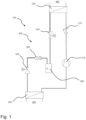
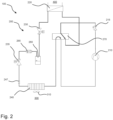
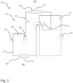
- Fig. 1 shows schematically and exemplarily a heat pump 100 with a vapor compression system or refrigeration circuit 200.
- the heat pump 100 is designed as a water/water heat pump or as a brine/water heat pump, so that a circuit reversal is not necessary, but is optionally possible, for example via additional switching valves.
Landscapes
- Engineering & Computer Science (AREA)
- Physics & Mathematics (AREA)
- Mechanical Engineering (AREA)
- Thermal Sciences (AREA)
- General Engineering & Computer Science (AREA)
- Defrosting Systems (AREA)
Applications Claiming Priority (1)
| Application Number | Priority Date | Filing Date | Title |
|---|---|---|---|
| DE102023136086.8A DE102023136086A1 (de) | 2023-12-20 | 2023-12-20 | Kältekreis einer Wärmepumpe und Wärmepumpe |
Publications (1)
| Publication Number | Publication Date |
|---|---|
| EP4575353A1 true EP4575353A1 (fr) | 2025-06-25 |
Family
ID=93656037
Family Applications (1)
| Application Number | Title | Priority Date | Filing Date |
|---|---|---|---|
| EP24215450.8A Pending EP4575353A1 (fr) | 2023-12-20 | 2024-11-26 | Circuit de refroidissement de pompe à chaleur et pompe à chaleur |
Country Status (2)
| Country | Link |
|---|---|
| EP (1) | EP4575353A1 (fr) |
| DE (1) | DE102023136086A1 (fr) |
Citations (4)
| Publication number | Priority date | Publication date | Assignee | Title |
|---|---|---|---|---|
| JPS5736572U (fr) * | 1980-08-11 | 1982-02-26 | ||
| JP2003139382A (ja) * | 2001-10-31 | 2003-05-14 | Mitsubishi Electric Corp | 空気調和機 |
| EP2664868B1 (fr) | 2012-05-15 | 2021-03-17 | Stiebel Eltron GmbH & Co. KG | Dispositif de pompe à chaleur et évaporateur pour un dispositif de pompe à chaleur |
| US20220106513A1 (en) * | 2019-06-19 | 2022-04-07 | Daikin Industries, Ltd. | Refrigerant-containing composition, use of same, refrigerator having same, operation method for said refrigerator, and refrigeration cycle device equipped with same |
Family Cites Families (3)
| Publication number | Priority date | Publication date | Assignee | Title |
|---|---|---|---|---|
| EP3147592A1 (fr) | 2015-09-22 | 2017-03-29 | Honeywell spol s.r.o. | Système de compression de vapeur avec sous-refroidissement |
| US10830515B2 (en) | 2015-10-21 | 2020-11-10 | Mitsubishi Electric Research Laboratories, Inc. | System and method for controlling refrigerant in vapor compression system |
| JP7280521B2 (ja) | 2021-03-31 | 2023-05-24 | ダイキン工業株式会社 | ヒートポンプ装置 |
-
2023
- 2023-12-20 DE DE102023136086.8A patent/DE102023136086A1/de active Pending
-
2024
- 2024-11-26 EP EP24215450.8A patent/EP4575353A1/fr active Pending
Patent Citations (4)
| Publication number | Priority date | Publication date | Assignee | Title |
|---|---|---|---|---|
| JPS5736572U (fr) * | 1980-08-11 | 1982-02-26 | ||
| JP2003139382A (ja) * | 2001-10-31 | 2003-05-14 | Mitsubishi Electric Corp | 空気調和機 |
| EP2664868B1 (fr) | 2012-05-15 | 2021-03-17 | Stiebel Eltron GmbH & Co. KG | Dispositif de pompe à chaleur et évaporateur pour un dispositif de pompe à chaleur |
| US20220106513A1 (en) * | 2019-06-19 | 2022-04-07 | Daikin Industries, Ltd. | Refrigerant-containing composition, use of same, refrigerator having same, operation method for said refrigerator, and refrigeration cycle device equipped with same |
Also Published As
| Publication number | Publication date |
|---|---|
| DE102023136086A1 (de) | 2025-06-26 |
Similar Documents
| Publication | Publication Date | Title |
|---|---|---|
| DE112016006864B4 (de) | Klimaanlage | |
| DE102009014607B4 (de) | Kältemittelkreislaufvorrichtung | |
| EP3648997B1 (fr) | Installation frigorifique pour véhicule pourvue d'un circuit de réfrigération équipé d'un échangeur thermique et échangeur thermique conçu pour une telle installation frigorifique | |
| DE112019007729B4 (de) | Klimaanlage | |
| DE112019007078T5 (de) | Klimagerät | |
| EP3344931B1 (fr) | Appareil de froid pourvu d'une pluralité de compartiments de stockage | |
| DE112022006832T5 (de) | Klimatisierungsgerät | |
| WO2009141282A2 (fr) | Appareil frigorifique à stockage du fluide frigorigène dans le condenseur et procédé correspondant | |
| DE69913184T2 (de) | Kälteeinrichtung mit zwei kältemitteln | |
| EP2500676A1 (fr) | Pompe à chaleur | |
| DE102021200238A1 (de) | Klimaanlage | |
| DE102021210534A1 (de) | Multi-Klimaanlage für Heiz- und Kühlbetriebe | |
| DE112019006658T5 (de) | Klimaanlage | |
| EP4575353A1 (fr) | Circuit de refroidissement de pompe à chaleur et pompe à chaleur | |
| EP2674698A1 (fr) | Installation de pompes à chaleur | |
| EP2812638B1 (fr) | Dispositif pompe à chaleur | |
| DE102021200237A1 (de) | Klimaanlage | |
| DE19832682C2 (de) | Abtaueinrichtung für einen Verdampfer einer Wärmepumpe oder eines Klimageräts | |
| EP4575354A1 (fr) | Circuit de refroidissement d'une pompe à chaleur et pompe à chaleur | |
| DE102020122713B4 (de) | Verfahren zum Betreiben einer Wärmepumpe | |
| DE112022006797T5 (de) | Klimagerät | |
| DE112021007291T5 (de) | Wärmequellenmaschine einer Kühlvorrichtung und Kühlvorrichtung einschließlich derselben | |
| DE112021004614T5 (de) | Klimaanlage | |
| DE202021106480U1 (de) | Umschaltbare Wärmepumpenanlage | |
| DE102023134321B4 (de) | Kältekreislauf und Wärmepumpe |
Legal Events
| Date | Code | Title | Description |
|---|---|---|---|
| PUAI | Public reference made under article 153(3) epc to a published international application that has entered the european phase |
Free format text: ORIGINAL CODE: 0009012 |
|
| STAA | Information on the status of an ep patent application or granted ep patent |
Free format text: STATUS: THE APPLICATION HAS BEEN PUBLISHED |
|
| AK | Designated contracting states |
Kind code of ref document: A1 Designated state(s): AL AT BE BG CH CY CZ DE DK EE ES FI FR GB GR HR HU IE IS IT LI LT LU LV MC ME MK MT NL NO PL PT RO RS SE SI SK SM TR |
|
| STAA | Information on the status of an ep patent application or granted ep patent |
Free format text: STATUS: REQUEST FOR EXAMINATION WAS MADE |
|
| 17P | Request for examination filed |
Effective date: 20260102 |