EP4575354A1 - Circuit de refroidissement d'une pompe à chaleur et pompe à chaleur - Google Patents
Circuit de refroidissement d'une pompe à chaleur et pompe à chaleur Download PDFInfo
- Publication number
- EP4575354A1 EP4575354A1 EP24217156.9A EP24217156A EP4575354A1 EP 4575354 A1 EP4575354 A1 EP 4575354A1 EP 24217156 A EP24217156 A EP 24217156A EP 4575354 A1 EP4575354 A1 EP 4575354A1
- Authority
- EP
- European Patent Office
- Prior art keywords
- refrigeration circuit
- recuperator
- refrigerant
- heat pump
- heat exchanger
- Prior art date
- Legal status (The legal status is an assumption and is not a legal conclusion. Google has not performed a legal analysis and makes no representation as to the accuracy of the status listed.)
- Pending
Links
Images









Classifications
-
- F—MECHANICAL ENGINEERING; LIGHTING; HEATING; WEAPONS; BLASTING
- F25—REFRIGERATION OR COOLING; COMBINED HEATING AND REFRIGERATION SYSTEMS; HEAT PUMP SYSTEMS; MANUFACTURE OR STORAGE OF ICE; LIQUEFACTION SOLIDIFICATION OF GASES
- F25B—REFRIGERATION MACHINES, PLANTS OR SYSTEMS; COMBINED HEATING AND REFRIGERATION SYSTEMS; HEAT PUMP SYSTEMS
- F25B30/00—Heat pumps
- F25B30/02—Heat pumps of the compression type
-
- F—MECHANICAL ENGINEERING; LIGHTING; HEATING; WEAPONS; BLASTING
- F25—REFRIGERATION OR COOLING; COMBINED HEATING AND REFRIGERATION SYSTEMS; HEAT PUMP SYSTEMS; MANUFACTURE OR STORAGE OF ICE; LIQUEFACTION SOLIDIFICATION OF GASES
- F25B—REFRIGERATION MACHINES, PLANTS OR SYSTEMS; COMBINED HEATING AND REFRIGERATION SYSTEMS; HEAT PUMP SYSTEMS
- F25B13/00—Compression machines, plants or systems, with reversible cycle
-
- F—MECHANICAL ENGINEERING; LIGHTING; HEATING; WEAPONS; BLASTING
- F25—REFRIGERATION OR COOLING; COMBINED HEATING AND REFRIGERATION SYSTEMS; HEAT PUMP SYSTEMS; MANUFACTURE OR STORAGE OF ICE; LIQUEFACTION SOLIDIFICATION OF GASES
- F25B—REFRIGERATION MACHINES, PLANTS OR SYSTEMS; COMBINED HEATING AND REFRIGERATION SYSTEMS; HEAT PUMP SYSTEMS
- F25B25/00—Machines, plants or systems, using a combination of modes of operation covered by two or more of the groups F25B1/00 - F25B23/00
- F25B25/005—Machines, plants or systems, using a combination of modes of operation covered by two or more of the groups F25B1/00 - F25B23/00 using primary and secondary systems
-
- F—MECHANICAL ENGINEERING; LIGHTING; HEATING; WEAPONS; BLASTING
- F25—REFRIGERATION OR COOLING; COMBINED HEATING AND REFRIGERATION SYSTEMS; HEAT PUMP SYSTEMS; MANUFACTURE OR STORAGE OF ICE; LIQUEFACTION SOLIDIFICATION OF GASES
- F25B—REFRIGERATION MACHINES, PLANTS OR SYSTEMS; COMBINED HEATING AND REFRIGERATION SYSTEMS; HEAT PUMP SYSTEMS
- F25B41/00—Fluid-circulation arrangements
- F25B41/20—Disposition of valves, e.g. of on-off valves or flow control valves
-
- F—MECHANICAL ENGINEERING; LIGHTING; HEATING; WEAPONS; BLASTING
- F25—REFRIGERATION OR COOLING; COMBINED HEATING AND REFRIGERATION SYSTEMS; HEAT PUMP SYSTEMS; MANUFACTURE OR STORAGE OF ICE; LIQUEFACTION SOLIDIFICATION OF GASES
- F25B—REFRIGERATION MACHINES, PLANTS OR SYSTEMS; COMBINED HEATING AND REFRIGERATION SYSTEMS; HEAT PUMP SYSTEMS
- F25B41/00—Fluid-circulation arrangements
- F25B41/30—Expansion means; Dispositions thereof
- F25B41/39—Dispositions with two or more expansion means arranged in series, i.e. multi-stage expansion, on a refrigerant line leading to the same evaporator
-
- F—MECHANICAL ENGINEERING; LIGHTING; HEATING; WEAPONS; BLASTING
- F25—REFRIGERATION OR COOLING; COMBINED HEATING AND REFRIGERATION SYSTEMS; HEAT PUMP SYSTEMS; MANUFACTURE OR STORAGE OF ICE; LIQUEFACTION SOLIDIFICATION OF GASES
- F25B—REFRIGERATION MACHINES, PLANTS OR SYSTEMS; COMBINED HEATING AND REFRIGERATION SYSTEMS; HEAT PUMP SYSTEMS
- F25B43/00—Arrangements for separating or purifying gases or liquids; Arrangements for vaporising the residuum of liquid refrigerant, e.g. by heat
-
- F—MECHANICAL ENGINEERING; LIGHTING; HEATING; WEAPONS; BLASTING
- F25—REFRIGERATION OR COOLING; COMBINED HEATING AND REFRIGERATION SYSTEMS; HEAT PUMP SYSTEMS; MANUFACTURE OR STORAGE OF ICE; LIQUEFACTION SOLIDIFICATION OF GASES
- F25B—REFRIGERATION MACHINES, PLANTS OR SYSTEMS; COMBINED HEATING AND REFRIGERATION SYSTEMS; HEAT PUMP SYSTEMS
- F25B47/00—Arrangements for preventing or removing deposits or corrosion, not provided for in another subclass
- F25B47/02—Defrosting cycles
-
- F—MECHANICAL ENGINEERING; LIGHTING; HEATING; WEAPONS; BLASTING
- F25—REFRIGERATION OR COOLING; COMBINED HEATING AND REFRIGERATION SYSTEMS; HEAT PUMP SYSTEMS; MANUFACTURE OR STORAGE OF ICE; LIQUEFACTION SOLIDIFICATION OF GASES
- F25B—REFRIGERATION MACHINES, PLANTS OR SYSTEMS; COMBINED HEATING AND REFRIGERATION SYSTEMS; HEAT PUMP SYSTEMS
- F25B2339/00—Details of evaporators; Details of condensers
- F25B2339/04—Details of condensers
- F25B2339/047—Water-cooled condensers
-
- F—MECHANICAL ENGINEERING; LIGHTING; HEATING; WEAPONS; BLASTING
- F25—REFRIGERATION OR COOLING; COMBINED HEATING AND REFRIGERATION SYSTEMS; HEAT PUMP SYSTEMS; MANUFACTURE OR STORAGE OF ICE; LIQUEFACTION SOLIDIFICATION OF GASES
- F25B—REFRIGERATION MACHINES, PLANTS OR SYSTEMS; COMBINED HEATING AND REFRIGERATION SYSTEMS; HEAT PUMP SYSTEMS
- F25B2400/00—Component parts or details not otherwise provided for in this subclass
- F25B2400/05—Compression system with heat exchange between particular parts of the system
- F25B2400/054—Compression system with heat exchange between particular parts of the system between the suction tube of the compressor and another part of the cycle
-
- F—MECHANICAL ENGINEERING; LIGHTING; HEATING; WEAPONS; BLASTING
- F25—REFRIGERATION OR COOLING; COMBINED HEATING AND REFRIGERATION SYSTEMS; HEAT PUMP SYSTEMS; MANUFACTURE OR STORAGE OF ICE; LIQUEFACTION SOLIDIFICATION OF GASES
- F25B—REFRIGERATION MACHINES, PLANTS OR SYSTEMS; COMBINED HEATING AND REFRIGERATION SYSTEMS; HEAT PUMP SYSTEMS
- F25B2400/00—Component parts or details not otherwise provided for in this subclass
- F25B2400/13—Economisers
-
- F—MECHANICAL ENGINEERING; LIGHTING; HEATING; WEAPONS; BLASTING
- F25—REFRIGERATION OR COOLING; COMBINED HEATING AND REFRIGERATION SYSTEMS; HEAT PUMP SYSTEMS; MANUFACTURE OR STORAGE OF ICE; LIQUEFACTION SOLIDIFICATION OF GASES
- F25B—REFRIGERATION MACHINES, PLANTS OR SYSTEMS; COMBINED HEATING AND REFRIGERATION SYSTEMS; HEAT PUMP SYSTEMS
- F25B2400/00—Component parts or details not otherwise provided for in this subclass
- F25B2400/16—Receivers
-
- F—MECHANICAL ENGINEERING; LIGHTING; HEATING; WEAPONS; BLASTING
- F25—REFRIGERATION OR COOLING; COMBINED HEATING AND REFRIGERATION SYSTEMS; HEAT PUMP SYSTEMS; MANUFACTURE OR STORAGE OF ICE; LIQUEFACTION SOLIDIFICATION OF GASES
- F25B—REFRIGERATION MACHINES, PLANTS OR SYSTEMS; COMBINED HEATING AND REFRIGERATION SYSTEMS; HEAT PUMP SYSTEMS
- F25B2600/00—Control issues
- F25B2600/25—Control of valves
- F25B2600/2501—Bypass valves
-
- F—MECHANICAL ENGINEERING; LIGHTING; HEATING; WEAPONS; BLASTING
- F25—REFRIGERATION OR COOLING; COMBINED HEATING AND REFRIGERATION SYSTEMS; HEAT PUMP SYSTEMS; MANUFACTURE OR STORAGE OF ICE; LIQUEFACTION SOLIDIFICATION OF GASES
- F25B—REFRIGERATION MACHINES, PLANTS OR SYSTEMS; COMBINED HEATING AND REFRIGERATION SYSTEMS; HEAT PUMP SYSTEMS
- F25B31/00—Compressor arrangements
- F25B31/002—Lubrication
- F25B31/004—Lubrication oil recirculating arrangements
Definitions
- the present invention relates to a refrigeration circuit of a heat pump system and an associated heat pump system.
- Heat pump refrigeration circuits are well known.
- the current state of the art is refrigeration circuits consisting of a compressor, evaporator, condenser, and expansion valve. Refrigeration circuits with additional components are known, but they require high costs for little efficiency benefit.
- various additions have been implemented for different refrigerants, such as intermediate refrigerant injection for R410A and a recuperator for R454C.
- the object of the invention is to improve the efficiency of the refrigeration circuit.
- a further object is to keep the complexity and cost of the refrigeration circuit as low as possible.
- a further object of the invention is to achieve optimal use of environmental energy by using a flammable refrigerant such as R290.
- the defrost coil is preferably arranged directly before or after the refrigerant receiver.
- the respective inlet and outlet pipes are advantageously designed to extract the refrigerant at the bottom of the receiver. Their open ends are therefore advantageously arranged at a similar height.
- the expansion valves comprise a first expansion valve and a second expansion valve, and the first expansion valve is controllable independently of the second expansion valve.
- Independent control means that a heat pump control can control one of the two expansion valves without automatically influencing the other expansion valve.
- the first expansion valve is preferably located upstream of the refrigerant receiver in the direction of refrigerant flow
- the second expansion valve is preferably located downstream of the refrigerant receiver in the direction of refrigerant flow. If the flow direction is reversed, the assignment of the two expansion valves changes accordingly.
- the first expansion valve (230) is designed for subcooling control in heating mode and the second expansion valve (235) is designed for superheating control.
- the subcooling control regulates the degree of opening of the first expansion valve in the direction of refrigerant flow on the basis of a subcooling setpoint (UK setpoint) determined for the optimum efficiency of the refrigeration circuit at the respective operating point and an actual subcooling value (UK actual value) determined on the basis of the condensation temperature of the refrigerant in the condensing heat exchanger and the refrigerant outlet temperature from the condensing heat exchanger in such a way that the control deviation between the UK setpoint and the UK actual value is zero. If the UK actual value is too small, the first expansion valve is closed further and if the UK actual value is too large, the valve is opened further.
- UK setpoint subcooling setpoint
- UK actual value actual subcooling value
- the UK setpoint can, for example, be stored in a table for different condensation temperatures or determined using a model, without being limited to these methods.
- the superheat control regulates the degree of opening of the second expansion valve in the direction of refrigerant flow on the basis of a superheat setpoint (ÜB setpoint) determined for safe operation and optimum efficiency of the refrigeration circuit at the respective operating point and an actual superheat value (ÜB actual value) determined on the basis of the evaporation temperature of the refrigerant in the evaporating heat exchanger and the refrigerant outlet temperature from the evaporating heat exchanger in such a way that the control deviation between the ÜB setpoint and the ÜB actual value is zero. If the ÜB actual value is too small, the second expansion valve is closed further and if the ÜB actual value is too large, the second expansion valve is opened further.
- ÜB setpoint a superheat setpoint
- ÜB actual value actual superheat value
- a heat pump in particular an air-water heat pump, brine-water heat pump, air-air heat pump or water-water heat pump, with a refrigeration circuit according to the invention is proposed.
- the heat pump is designed as an air-water heat pump, brine-water heat pump or water-water heat pump and has a hydraulic circuit as a heat sink, wherein the hydraulic circuit has a changeover valve.
- control is designed to reverse the refrigerant circuit through the refrigerant collector.
- the reversal of the refrigerant circuit is advantageously carried out by the 4/2 way valve.
- the refrigerant collector is advantageously suitable for flow in two directions.
- the recuperator increases the efficiency of the refrigeration circuit by displacing the superheat.
- the desuperheater enables parallel hot gas desuperheating for hot water for heating purposes.
- Fig. 1 shows schematically and exemplarily a heat pump 100 with a vapor compression system or refrigeration circuit 200.
- the heat pump 100 is designed as a water/water heat pump or as a brine/water heat pump, so that a circuit reversal is not necessary, but is optionally possible, for example via additional switching valves.
- a compressor 210 In the refrigeration circuit 200, a compressor 210, an optional check valve 215, a first heat exchanger 220, a first throttle element 230, a second throttle element 235, a second heat exchanger 240, a refrigerant receiver 260 and an optional filter dryer 265 are shown.
- the refrigerant is increased in pressure, or compressed, to high pressure (HD).
- the refrigerant compressed to the high pressure (HD) then flows, in heating mode, through the optional check valve 215 downstream of the compressor 210 and to the first heat exchanger 220.
- the first heat exchanger 220 is operated as a condensing heat exchanger in heating mode and is designed as a condenser in which the refrigerant can be condensed and preferably subcooled.
- the first heat exchanger 220 is connected to a heat sink system 400, in which, in particular, a heating medium is circulated in a heating medium flow direction.
- the first throttle element 230 is configured as an intermediate pressure throttle element, in which the refrigerant is expanded from a high pressure (HD) to an intermediate pressure (ZD).
- This intermediate pressure is also referred to as the intermediate pressure (MD).
- the second heat exchanger 240 is operated as an evaporating heat exchanger in heating mode and is designed as an evaporator in which the refrigerant is evaporated.
- a temperature sensor (not shown) is provided in the exemplary embodiment and is suitable for measuring the temperature of the refrigerant at a high pressure (HD) during cooling operation as it exits the heat exchanger condensing during cooling operation and transmitting the temperature to the controller.
- the controller is suitable for using the temperature sensor during cooling operation to measure the temperature of the refrigerant at a high pressure (HD).
- a heat source system 300 is provided.
- the heat source system 300 serves to exchange heat of a source medium with the refrigerant, whereby energy of the heat source system 300 is exchanged with the vapor compression system 200.
- the heat source system 300 is a system with water or brine as the source medium.
- the heat sink system 400 can, in particular, be a hot water system via an apartment station, a hot water tank, or even a conventional building heating system.
- the temperature of the refrigerant is significantly reduced.
- the first heat exchanger 220 used here is designed as a condensing heat exchanger such that it can accommodate liquefied refrigerant, which can also be further subcooled in the first heat exchanger 220, i.e., brought to temperatures below the condensation temperature.
- the first heat exchanger 220 is suitable for accommodating liquid refrigerant at different levels or different masses or volumes of liquid refrigerant.
- the liquefied and preferably subcooled refrigerant flows from the first heat exchanger 220 to the first throttle element 230.
- the first throttle element 230 which is operated as an intermediate pressure throttle element in heating mode, the refrigerant is expanded to the intermediate pressure ZD.
- the refrigerant at the intermediate pressure ZD continues to flow after the first throttle element 230 to the refrigerant collector 260.
- the refrigerant still at the intermediate pressure ZD, now flows into the second throttle element 235, which operates as a low-pressure throttle element in heating mode.
- the refrigerant is expanded to the low pressure ND in heating mode, continues to flow in a low-pressure flow direction into the second heat exchanger 240, which operates as an evaporating heat exchanger in heating mode, absorbs energy, and evaporates—a cycle in the vapor compression system 200 is closed.
- the refrigerant collector 260 advantageously accommodates a mass of liquid refrigerant, which in particular should not remain in the condensing heat exchanger. Furthermore, active refrigerant, which participates in particular in thermal processes in the vapor compression system, is located in the evaporating heat exchanger, the compressor, and any internal heat exchanger provided. The refrigerant collector 260 thus serves as a buffer storage for refrigerant not required for the thermal processes.
- Fig. 2 shows schematically and exemplarily another refrigeration circuit 200 of a heat pump 100.
- the refrigeration circuit 200 of the Fig. 2 differs from the refrigeration circuit of the Fig. 1 in that the heat source system 300 provides air as the heat source and, accordingly, a fan 310 is provided that conveys air through the heat exchanger 240.
- An injection capillary 247 is also provided for the heat exchanger 240, which in this embodiment is configured as an air/refrigerant heat exchanger.
- a switching valve 270 is provided, with which the flow direction of the refrigeration circuit 200 can be reversed.
- heating mode energy is transferred from the source medium to the refrigerant in the second heat exchanger 240, thus evaporating the refrigerant in the second heat exchanger 240, which operates as an evaporating heat exchanger in heating mode.
- the controller treats the first heat exchanger 220 in heating mode as a condensing heat exchanger.
- cooling mode i.e. when the changeover valve 270 is in the Fig. 2 In a different position (not shown), energy is transferred from the refrigerant to the source medium, thus condensing the refrigerant in the second heat exchanger 240, which operates as a condensing heat exchanger in the cooling mode.
- the controller treats the second heat exchanger 240 as a condensing heat exchanger in the cooling mode.
- the refrigeration circuit 200 absorbs source energy QQ from the heat source system 300.
- the refrigerant evaporates in the second heat exchanger 240 before the refrigerant flows into the compressor 210 or is sucked in by it.
- Fig. 3 shows schematically and exemplarily a third refrigeration circuit 200.
- the refrigeration circuit of the Fig. 3 differs from the refrigeration circuit 200 of the Fig. 2 in which the first heat exchanger 220 is also designed as a refrigerant/air heat exchanger.
- the heat pump 100 of the Fig. 3 is therefore an air-to-air heat pump. Therefore, a fan 410 is also provided in the vicinity of the first heat exchanger 220.
- Fig. 4 shows schematically and exemplarily a fourth refrigeration circuit 200.
- the refrigeration circuit 200 of the Fig. 4 In addition to the cooling circuit, the Fig. 2 a defrost coil 290 which is arranged between the first throttle element 230 and the refrigerant collector 260.
- the defrost coil 290 is in particular a part of the refrigeration circuit in which liquid refrigerant flows and which is designed to heat a defrost pan of the second heat exchanger 240.
- the oil separator 250 separates oil, in particular compressor oil, from the refrigerant and returns it to the compressor 210 via an oil line 251, 252.
- oil line 251, 252 Different designs of the oil line 251, 252 are conceivable; for example, the oil line 251 can return directly to the compressor 210 or the oil line 252 can return to a suction line upstream of the compressor.
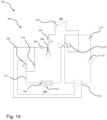
- Fig. 14 shows a further embodiment of a refrigeration circuit 200 with recuperator 275. If the flow continues through the recuperator 275 during operation of the refrigeration circuit 200 in reverse mode, unwanted heat transfer may occur. To prevent this, the recuperator 275 is bridged or bypassed on the liquid side during circuit reversal in this preferred embodiment by means of a check valve 279 and a closed second throttle device 235.
Landscapes
- Engineering & Computer Science (AREA)
- Physics & Mathematics (AREA)
- Mechanical Engineering (AREA)
- Thermal Sciences (AREA)
- General Engineering & Computer Science (AREA)
- Chemical & Material Sciences (AREA)
- Analytical Chemistry (AREA)
- Power Engineering (AREA)
- Compression-Type Refrigeration Machines With Reversible Cycles (AREA)
Applications Claiming Priority (1)
| Application Number | Priority Date | Filing Date | Title |
|---|---|---|---|
| DE102023136088.4A DE102023136088A1 (de) | 2023-12-20 | 2023-12-20 | Kältekreis einer Wärmepumpe und Wärmepumpen |
Publications (1)
| Publication Number | Publication Date |
|---|---|
| EP4575354A1 true EP4575354A1 (fr) | 2025-06-25 |
Family
ID=93796887
Family Applications (1)
| Application Number | Title | Priority Date | Filing Date |
|---|---|---|---|
| EP24217156.9A Pending EP4575354A1 (fr) | 2023-12-20 | 2024-12-03 | Circuit de refroidissement d'une pompe à chaleur et pompe à chaleur |
Country Status (2)
| Country | Link |
|---|---|
| EP (1) | EP4575354A1 (fr) |
| DE (1) | DE102023136088A1 (fr) |
Citations (6)
| Publication number | Priority date | Publication date | Assignee | Title |
|---|---|---|---|---|
| WO2012040864A1 (fr) * | 2010-09-29 | 2012-04-05 | Erik Vincent Granwehr | Pompe à chaleur |
| DE102011118162A1 (de) * | 2011-11-10 | 2013-05-16 | Audi Ag | Kombinierte Kälteanlage und Wärmepumpe und Verfahren zum Betreiben der Anlage mit funktionsabhängiger Kältemittelverlagerung innerhalb des Kältemittelkreislaufes |
| DE112014005129T5 (de) * | 2013-11-08 | 2016-07-28 | Denso Corporation | Kompressor und Kälteerzeugungskreiseinrichtung |
| EP2664868B1 (fr) | 2012-05-15 | 2021-03-17 | Stiebel Eltron GmbH & Co. KG | Dispositif de pompe à chaleur et évaporateur pour un dispositif de pompe à chaleur |
| EP3165852B1 (fr) * | 2015-11-09 | 2021-06-09 | Mitsubishi Electric Corporation | Pompe à chaleur antigivre |
| EP3885670A1 (fr) * | 2014-06-27 | 2021-09-29 | Mitsubishi Electric Corporation | Appareil de cycle de réfrigération |
-
2023
- 2023-12-20 DE DE102023136088.4A patent/DE102023136088A1/de active Pending
-
2024
- 2024-12-03 EP EP24217156.9A patent/EP4575354A1/fr active Pending
Patent Citations (6)
| Publication number | Priority date | Publication date | Assignee | Title |
|---|---|---|---|---|
| WO2012040864A1 (fr) * | 2010-09-29 | 2012-04-05 | Erik Vincent Granwehr | Pompe à chaleur |
| DE102011118162A1 (de) * | 2011-11-10 | 2013-05-16 | Audi Ag | Kombinierte Kälteanlage und Wärmepumpe und Verfahren zum Betreiben der Anlage mit funktionsabhängiger Kältemittelverlagerung innerhalb des Kältemittelkreislaufes |
| EP2664868B1 (fr) | 2012-05-15 | 2021-03-17 | Stiebel Eltron GmbH & Co. KG | Dispositif de pompe à chaleur et évaporateur pour un dispositif de pompe à chaleur |
| DE112014005129T5 (de) * | 2013-11-08 | 2016-07-28 | Denso Corporation | Kompressor und Kälteerzeugungskreiseinrichtung |
| EP3885670A1 (fr) * | 2014-06-27 | 2021-09-29 | Mitsubishi Electric Corporation | Appareil de cycle de réfrigération |
| EP3165852B1 (fr) * | 2015-11-09 | 2021-06-09 | Mitsubishi Electric Corporation | Pompe à chaleur antigivre |
Also Published As
| Publication number | Publication date |
|---|---|
| DE102023136088A1 (de) | 2025-06-26 |
Similar Documents
| Publication | Publication Date | Title |
|---|---|---|
| DE60123816T2 (de) | Umkehrbare dampfverdichtungsanordnung | |
| DE68908181T2 (de) | Verfahren zum betrieb eines kaltdampfprozesses unter trans- oder überkritischen bedingungen. | |
| EP3648997B1 (fr) | Installation frigorifique pour véhicule pourvue d'un circuit de réfrigération équipé d'un échangeur thermique et échangeur thermique conçu pour une telle installation frigorifique | |
| DE102007001878A1 (de) | Ejektorpumpen-Kühlkreisvorrichtung | |
| DE10138255A1 (de) | Anordnung für Kaskadenkälteanlage | |
| DE3422391A1 (de) | Kaelte erzeugende vorrichtung | |
| DE112014000558T5 (de) | Kapazitätsmodulierung einer Ausdehnungsvorrichtung einer Heizungs-, Lüftungs- und Klimaanlage | |
| EP2297531A2 (fr) | Appareil frigorifique à stockage du fluide frigorigène dans le condenseur et procédé correspondant | |
| DE112013001478T5 (de) | Kühlsystem | |
| EP2026019A2 (fr) | Installation d'équilibrage de la température à base de pompe thermique | |
| DE69513765T2 (de) | Kälteanlage | |
| DE112018001092B4 (de) | Ejektormodul | |
| EP2674698A1 (fr) | Installation de pompes à chaleur | |
| DE19829335C2 (de) | Kälteanlage | |
| EP4575354A1 (fr) | Circuit de refroidissement d'une pompe à chaleur et pompe à chaleur | |
| DE69921871T2 (de) | Absorptionskälteanlage mit Kupplung von Kondensat und Lösung | |
| EP2812638B1 (fr) | Dispositif pompe à chaleur | |
| WO2004055454A1 (fr) | Circuit de refrigerant pour une installation de climatisation de vehicule automobile | |
| DE19832682C2 (de) | Abtaueinrichtung für einen Verdampfer einer Wärmepumpe oder eines Klimageräts | |
| EP4575353A1 (fr) | Circuit de refroidissement de pompe à chaleur et pompe à chaleur | |
| DE112021007291T5 (de) | Wärmequellenmaschine einer Kühlvorrichtung und Kühlvorrichtung einschließlich derselben | |
| DE202011102503U1 (de) | Wärmepumpenanlage | |
| DE202021106480U1 (de) | Umschaltbare Wärmepumpenanlage | |
| EP4495504B1 (fr) | Circuit de réfrigérant et pompe à chaleur | |
| EP3961129A1 (fr) | Pompe à chaleur et procédé de fonctionnement d'une pompe à chaleur |
Legal Events
| Date | Code | Title | Description |
|---|---|---|---|
| PUAI | Public reference made under article 153(3) epc to a published international application that has entered the european phase |
Free format text: ORIGINAL CODE: 0009012 |
|
| STAA | Information on the status of an ep patent application or granted ep patent |
Free format text: STATUS: THE APPLICATION HAS BEEN PUBLISHED |
|
| AK | Designated contracting states |
Kind code of ref document: A1 Designated state(s): AL AT BE BG CH CY CZ DE DK EE ES FI FR GB GR HR HU IE IS IT LI LT LU LV MC ME MK MT NL NO PL PT RO RS SE SI SK SM TR |
|
| STAA | Information on the status of an ep patent application or granted ep patent |
Free format text: STATUS: REQUEST FOR EXAMINATION WAS MADE |
|
| 17P | Request for examination filed |
Effective date: 20260102 |
|
| STAA | Information on the status of an ep patent application or granted ep patent |
Free format text: STATUS: EXAMINATION IS IN PROGRESS |