EP4575474A1 - Verfahren zur messung eines überlagerungsfehlers, entsprechendes instrumentalsystem und computerprogrammprodukt - Google Patents
Verfahren zur messung eines überlagerungsfehlers, entsprechendes instrumentalsystem und computerprogrammprodukt Download PDFInfo
- Publication number
- EP4575474A1 EP4575474A1 EP24221414.6A EP24221414A EP4575474A1 EP 4575474 A1 EP4575474 A1 EP 4575474A1 EP 24221414 A EP24221414 A EP 24221414A EP 4575474 A1 EP4575474 A1 EP 4575474A1
- Authority
- EP
- European Patent Office
- Prior art keywords
- angle
- reciprocal
- defect
- overlay
- incidence
- Prior art date
- Legal status (The legal status is an assumption and is not a legal conclusion. Google has not performed a legal analysis and makes no representation as to the accuracy of the status listed.)
- Pending
Links
Images


Classifications
-
- G—PHYSICS
- G01—MEASURING; TESTING
- G01N—INVESTIGATING OR ANALYSING MATERIALS BY DETERMINING THEIR CHEMICAL OR PHYSICAL PROPERTIES
- G01N23/00—Investigating or analysing materials by the use of wave or particle radiation, e.g. X-rays or neutrons, not covered by groups G01N3/00 – G01N17/00, G01N21/00 or G01N22/00
- G01N23/20—Investigating or analysing materials by the use of wave or particle radiation, e.g. X-rays or neutrons, not covered by groups G01N3/00 – G01N17/00, G01N21/00 or G01N22/00 by using diffraction of the radiation by the materials, e.g. for investigating crystal structure; by using scattering of the radiation by the materials, e.g. for investigating non-crystalline materials; by using reflection of the radiation by the materials
- G01N23/2055—Analysing diffraction patterns
-
- G—PHYSICS
- G03—PHOTOGRAPHY; CINEMATOGRAPHY; ANALOGOUS TECHNIQUES USING WAVES OTHER THAN OPTICAL WAVES; ELECTROGRAPHY; HOLOGRAPHY
- G03F—PHOTOMECHANICAL PRODUCTION OF TEXTURED OR PATTERNED SURFACES, e.g. FOR PRINTING, FOR PROCESSING OF SEMICONDUCTOR DEVICES; MATERIALS THEREFOR; ORIGINALS THEREFOR; APPARATUS SPECIALLY ADAPTED THEREFOR
- G03F7/00—Photomechanical, e.g. photolithographic, production of textured or patterned surfaces, e.g. printing surfaces; Materials therefor, e.g. comprising photoresists; Apparatus specially adapted therefor
- G03F7/70—Microphotolithographic exposure; Apparatus therefor
- G03F7/70483—Information management; Active and passive control; Testing; Wafer monitoring, e.g. pattern monitoring
- G03F7/70605—Workpiece metrology
- G03F7/70616—Monitoring the printed patterns
- G03F7/70633—Overlay, i.e. relative alignment between patterns printed by separate exposures in different layers, or in the same layer in multiple exposures or stitching
-
- G—PHYSICS
- G01—MEASURING; TESTING
- G01N—INVESTIGATING OR ANALYSING MATERIALS BY DETERMINING THEIR CHEMICAL OR PHYSICAL PROPERTIES
- G01N2223/00—Investigating materials by wave or particle radiation
- G01N2223/05—Investigating materials by wave or particle radiation by diffraction, scatter or reflection
- G01N2223/054—Investigating materials by wave or particle radiation by diffraction, scatter or reflection small angle scatter
-
- G—PHYSICS
- G01—MEASURING; TESTING
- G01N—INVESTIGATING OR ANALYSING MATERIALS BY DETERMINING THEIR CHEMICAL OR PHYSICAL PROPERTIES
- G01N2223/00—Investigating materials by wave or particle radiation
- G01N2223/60—Specific applications or type of materials
- G01N2223/611—Specific applications or type of materials patterned objects; electronic devices
Definitions
- the present invention relates to a method for measuring an error in the superposition of two line arrays during the manufacture of a microelectronic component, this method implementing a grazing-incidence small-angle X-ray scattering technique or GISAXS (for "grazing-incidence small-angle X-ray scattering").
- the documents US 9 885 962 B2 Or FR 3133673 present a method for measuring the overlay using a transmission X-ray scattering technique or T-SAXS. This involves illuminating the target carried by the component with an X-ray beam and evaluating the overlay from the transmitted intensity for different angles of incidence of the X-ray beam.
- T-SAXS transmission X-ray scattering technique
- this technique remains difficult to implement since it requires the transmission of X-rays through the thickness of the component. This is problematic because the different levels are deposited on a substrate, for example silicon, which has a relatively large thickness, typically 700 ⁇ m.
- a transmission overlay measurement therefore requires that the X-ray beam have a high intensity.
- synchrotron sources are capable of delivering the required intensity. However, such sources are not compatible with deployment along a production line.
- the aim of the present invention is to propose a method for measuring the overlay based on the implementation of a GISAXS X-ray reflection scattering technique.
- the invention relates to a method for measuring a covering defect affecting a pattern resulting from the superposition of a first network of lines carried by a first level of a microelectronic component and a second network of lines carried by a second level of the microelectronic component, an orthonormal reference frame x 0 y 0 z 0 being associated with the microelectronic component, the lines of the first and second networks of lines being oriented according to the direction xo, and the first and second line networks being superimposed along the direction zo, the measurement method implementing a small angle X-ray scattering technique by reflection - GI-SAXS making it possible to illuminate the pattern at an angle of incidence ⁇ i , characterized in that the method comprises the steps of: acquiring, by means of a detector placed in an observation plane, an orthonormal xyz reference frame being associated with the detector so that the z axis is parallel to the z 0 axis and the x axis, normal to the observation plane
- the invention also relates to an instrumental system of the small angle X-ray scattering by reflection type - GI-SAXS, comprising an X-ray source, a detector, acquisition electronics and a computer, programmed for the implementation of the preceding measurement method.
- the invention finally relates to a computer program product comprising software instructions which, when executed by a computer of the preceding instrumental system, allows the latter to implement the preceding method.
- the invention also relates to an instrumental system of the GISAXS type, comprising a computer and a detector connected to the computer, characterized in that the computer is suitably programmed so that the instrumental system implements the preceding method.
- the intensity required to perform the measurement i.e. to collect sufficient intensity on the observation detector for a precise measurement, can then be provided by a less intense X-ray source, in particular a small so-called “laboratory” source, such as a Cu K- ⁇ source.
- a less intense X-ray source in particular a small so-called “laboratory” source, such as a Cu K- ⁇ source.
- laboratory such as a Cu K- ⁇ source.
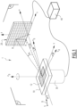
- FIG. 1 represents an instrumental system 1 making it possible to implement the overlay measurement method according to the invention on a sample 10.
- a source S illuminates the sample 10 and the light reflected by the sample 10 is imaged in an observation plane PO.
- An x, y, z frame of the instrumental system 1 is for example attached to the origin O of the observation plane PO, so that the normal direction to this plane is the x direction and the plane itself is defined by the y and z directions.
- the sample 10 is for example a microelectronic component on the flat surface of which a target 12 is provided.
- the target 12 comprises a first level carrying a first network of lines and a second network having a second network of lines.
- Each network is for example etched by implementing a lithography process during the manufacture of the level which carries it.
- a reference frame x 0 , y 0 , z 0 is attached to the center A of the target 12, so that the direction z0 (which corresponds to the stacking direction of the levels of the component 10) corresponds to the normal to the surface of the sample 10, that the direction xo corresponds to the direction of the lines of the line network of the target 12, and that the direction y 0 is orthogonal to the directions z 0 and x 0 , i.e. orthogonal to the direction of the lines of the line network.
- the sample 10 is placed on a support 30 of the instrumental system 1.
- the sample 10 is oriented so that the axis z0 is parallel to the axis z of the instrumental system 1, and that the plane x 0 y 0 of the surface of the sample 10 coincides with the plane xy.
- the X-ray source S emits an X-ray beam in a direction of incidence D on the target 12 of the sample 10.
- the PI incidence plane corresponds to the xz plane.
- the y direction is therefore the direction normal to the PI incidence plane.
- a GISAXS measurement is carried out with a small angle of incidence ⁇ i , between the x and D directions, for example a few radians (between 0.1-10 degrees).
- the support 30 makes it possible to rotate the sample 10 around the direction z 0 so as to modify an illumination angle ⁇ between the direction xo and the direction x, which is also the angle between the direction yo and the direction y.
- the illumination angle ⁇ when it is not zero, causes there to be a misalignment between the direction of the lines of the line network (direction x 0 ) and the plane of incidence PI.
- the incident beam falls at point A of sample 10. It is diffused by target 12 so as to form an image in the observation plane PO.
- a detector 20 is placed in the observation plane PO. It is for example composed of a matrix of X-ray sensors, the lines of which are arranged in the y direction and the ranks in the z direction. Each sensor is capable of measuring an intensity.
- the intensity l at point B of the observation plane PO depends on the angle 20, defined between the direction AO and the projection of the direction AB in the horizontal xy plane, and on the angle ⁇ f between the direction AB and the projection of the direction AB in the horizontal xy plane.
- the detector 20 is connected to an electronic device, shown schematically in the Figure 1 by a cube bearing the reference 40.
- the device 40 comprises control electronics making it possible to control the support 30 so that it positions the sample 10 according to a set value of the illumination angle ⁇ .
- the device 40 also includes acquisition electronics making it possible to carry out suitable pre-processing on the signals delivered by each of the sensors of the detector 20 and to digitize them.
- the device 40 further comprises a computer for processing the pre-processed and digitized signals.
- the computer is a computer comprising calculation means, such as a processor, and storage means, such as a memory.
- the memory stores in particular the instructions of computer programs, in particular a program whose execution allows the implementation of the measurement method according to the invention.
- This reciprocal image belongs to the reciprocal space whose reciprocal coordinates are the spatial frequencies q x , q y and q z .
- the key information is found at the level of the Bragg spots (i.e., the scattering peaks).
- the p-order Bragg spot is located at a combination of values q y p q z p unique.
- q y p 2 ⁇ cos ⁇ ⁇ ⁇ 2 ⁇ sin ⁇ i 2 cos ⁇ cos ⁇ ⁇ ⁇ 1 + 1 ⁇ ⁇ 2 p 2 b 2 sin ⁇ i 2 cos ⁇ 2 1 ⁇ 2bsin ⁇ p ⁇ 1 2
- q z p 2 ⁇ sin ⁇ i cos ⁇ i cos ⁇ ⁇ ⁇ 1 + 1 ⁇ ⁇ 2 p 2 b 2 sin ⁇ i 2 cos ⁇ 2 1 ⁇ 2bsin ⁇ p ⁇ 1 2
- ⁇ is the X-ray wavelength
- b the periodicity of the pattern
- p is the order of the scattering peak
- ⁇ i is the angle of incidence
- ⁇ is the illumination angle.
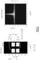
- the left part of the Figure 2 represents, in the direct space of the coordinates y0 and z0 (or z), a fraction of the pattern carried by the target 12 of the component 10. This is the superposition, in the thickness of the component 10 (i.e. in the direction z0), of a first network of lines 40 and a second network of lines 50. For example, two lines 41 and 42 of the first network and two lines 51 and 52 of the second network are represented. The lines of each of these networks extend in the direction x0, orthogonal to the plane of the figure.
- a line has a substantially rectangular section in the plane z0y0, of width I and depth p. Two neighboring lines of the same network of lines are spaced by a step d.
- the two networks of lines 40 and 50 are separated from each other by a distance D.
- the first and second line networks are perfectly superimposed along the z0 direction.
- the angle of incidence ⁇ i is 0.2 degrees and one line of the line array has a width and depth of 40 nm.
- the pitch d is 100 nm and the distance D is 40 nm, with the two line arrays directly superimposed on each other.
- FIG. 3 is similar to the Figure 2 except that the first and second line arrays 40 and 50 are now slightly offset from each other along the y0 direction of an OVL overlay.
- the obtained reciprocal image is represented on the right part of the Figure 3 . It is a representation in the reciprocal space of the spatial frequencies q y and q z , respectively conjugates of the y and z coordinates.
- the GISAXS signal is only obtained for positive q z . Indeed, the exit angles, ⁇ f , less than 0 are masked from the detector by the sample.
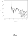
- FIG. 4 is a graph superimposing a set of curves giving the intensity I as a function of the coordinates q z .
- Each curve is indexed by the index i, or order. i is a non-zero integer.
- Each curve corresponds to a vertical cut in the reciprocal image of the Figure 3 .
- Each cut is associated with a value q y i particular according to the direction q y of the reciprocal image of the Figure 3 .
- the step ⁇ between two successive values of q y i is equal to the distance between two Bragg rods, but this is not necessary.
- the signal intensity in this region is weak. It is difficult to exploit unless the exposure time is increased, which is incompatible with integration into a manufacturing chain and the multiplication of measurements.
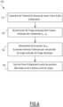
- Method 100 first consists of reconstructing the reciprocal image in the reciprocal space.
- the method 100 continues with a step 130 of determining the position along the q z axis of the nth minimum intensity for at least two sections verticals of the reciprocal image obtained in step 120.
- this is the first minimum since it has a strong contrast and can therefore be located precisely.
- more than two cuts are used to obtain more points and determine with greater precision the coefficients of the line connecting these points (for example by a least squares type regression method).
- a fourth step 140 the difference in position in q z of the minimum tracked as a function of the difference in position in q y makes it possible to extract the OVL overlay. If we are interested in the most intense region of the reciprocal image, that is to say one of the first minima of the intensity curves (close to line L1) equation (10) is used.
- the method 100 can be iterated by modifying the illumination angle ⁇ .
- the information is contained at the Bragg task level, it is therefore preferable to scan in ⁇ , to access different q y , q z , and thus obtain more information on the pattern.
- the pattern information is contained for a small angular range ⁇ , between -5 and 5°, preferably between -2 and 2, and even more preferably - 0.5 and 0.5. It is therefore this range if it is then advantageous to scan accurately.
- the instrumental system 1 is suitable for implementing the measurement method 100 just presented.
- the computer of the system 1 is suitably programmed to carry out the calculation steps, i.e. the steps other than the acquisition step, in particular calculating the overlay from equation (10).
Landscapes
- Physics & Mathematics (AREA)
- General Physics & Mathematics (AREA)
- Chemical & Material Sciences (AREA)
- Crystallography & Structural Chemistry (AREA)
- Health & Medical Sciences (AREA)
- Life Sciences & Earth Sciences (AREA)
- Analytical Chemistry (AREA)
- Biochemistry (AREA)
- General Health & Medical Sciences (AREA)
- Immunology (AREA)
- Pathology (AREA)
- Analysing Materials By The Use Of Radiation (AREA)
Applications Claiming Priority (1)
| Application Number | Priority Date | Filing Date | Title |
|---|---|---|---|
| FR2314490A FR3156907A1 (fr) | 2023-12-19 | 2023-12-19 | Procédé de mesure d’un défaut de recouvrement ; Système instrumental et produit programme d’ordinateur associés. |
Publications (1)
| Publication Number | Publication Date |
|---|---|
| EP4575474A1 true EP4575474A1 (de) | 2025-06-25 |
Family
ID=91072794
Family Applications (1)
| Application Number | Title | Priority Date | Filing Date |
|---|---|---|---|
| EP24221414.6A Pending EP4575474A1 (de) | 2023-12-19 | 2024-12-19 | Verfahren zur messung eines überlagerungsfehlers, entsprechendes instrumentalsystem und computerprogrammprodukt |
Country Status (2)
| Country | Link |
|---|---|
| EP (1) | EP4575474A1 (de) |
| FR (1) | FR3156907A1 (de) |
Citations (3)
| Publication number | Priority date | Publication date | Assignee | Title |
|---|---|---|---|---|
| US20150117610A1 (en) * | 2013-10-28 | 2015-04-30 | Kla-Tencor Corporation | Methods and apparatus for measuring semiconductor device overlay using x-ray metrology |
| US10545104B2 (en) * | 2015-04-28 | 2020-01-28 | Kla-Tencor Corporation | Computationally efficient X-ray based overlay measurement |
| EP4246135A1 (de) * | 2022-03-17 | 2023-09-20 | Commissariat à l'énergie atomique et aux énergies alternatives | Verbessertes verfahren zur messung der ausrichtung eines zeilenablenkungsfehlers in kleinen winkeln durch t-saxs-übertragung ; entsprechendes instrumentalsystem und computerprogrammprodukt |
-
2023
- 2023-12-19 FR FR2314490A patent/FR3156907A1/fr active Pending
-
2024
- 2024-12-19 EP EP24221414.6A patent/EP4575474A1/de active Pending
Patent Citations (5)
| Publication number | Priority date | Publication date | Assignee | Title |
|---|---|---|---|---|
| US20150117610A1 (en) * | 2013-10-28 | 2015-04-30 | Kla-Tencor Corporation | Methods and apparatus for measuring semiconductor device overlay using x-ray metrology |
| US9885962B2 (en) | 2013-10-28 | 2018-02-06 | Kla-Tencor Corporation | Methods and apparatus for measuring semiconductor device overlay using X-ray metrology |
| US10545104B2 (en) * | 2015-04-28 | 2020-01-28 | Kla-Tencor Corporation | Computationally efficient X-ray based overlay measurement |
| EP4246135A1 (de) * | 2022-03-17 | 2023-09-20 | Commissariat à l'énergie atomique et aux énergies alternatives | Verbessertes verfahren zur messung der ausrichtung eines zeilenablenkungsfehlers in kleinen winkeln durch t-saxs-übertragung ; entsprechendes instrumentalsystem und computerprogrammprodukt |
| FR3133673A1 (fr) | 2022-03-17 | 2023-09-22 | Commissariat à l'énergie atomique et aux énergies alternatives | Procédé amélioré de mesure d’un écart d’alignement par diffusion des rayons X aux petits angles par transmission - T-SAXS ; Système instrumental et produit programme d’ordinateur associés. |
Non-Patent Citations (1)
| Title |
|---|
| M. YAN ET AL.: "on the intersection of grating truncation rods with the Ewald sphere studied by grazing-incidence small-angle X-ray scattering", J. APPL. CRYST., vol. 40, 2007, pages 1050 - 1055 |
Also Published As
| Publication number | Publication date |
|---|---|
| FR3156907A1 (fr) | 2025-06-20 |
Similar Documents
| Publication | Publication Date | Title |
|---|---|---|
| EP2368105B1 (de) | Verfahren zur nichtdestruktiven inspektion eines mechanischen teils | |
| WO2017108400A1 (fr) | Dispositif et procede de mesure de hauteur en presence de couches minces | |
| FR2732763A1 (fr) | Procede et systeme pour profiler une surface d'objet en utilisant une longueur d'onde equivalente importante | |
| EP1580524B1 (de) | Verfahren und Vorrichtung zur Charakterisierung von Strukturschäden mittels Moiré- Schatten | |
| EP3749949B1 (de) | Terahertz-reflexionsbildgebungssystem | |
| JP2016526702A (ja) | Euvリソグラフィのアクティニックマスク検査用の走査型コヒーレント回折イメージング方法およびシステム | |
| KR20140134339A (ko) | 근적외선 스펙트럼 범위를 이용한 오버레이 메트롤러지 | |
| EP1157261A2 (de) | Verfahren und vorrichtung zur analyse einer hochdynamischen wellenfront | |
| EP4575474A1 (de) | Verfahren zur messung eines überlagerungsfehlers, entsprechendes instrumentalsystem und computerprogrammprodukt | |
| GB2266366A (en) | Light beam angle detection | |
| EP4246135B1 (de) | Verbessertes verfahren zur messung der ausrichtung eines zeilenablenkungsfehlers in kleinen winkeln durch t-saxs-übertragung ; entsprechendes instrumentalsystem und computerprogrammprodukt | |
| EP1682879B1 (de) | Verwendung einer optischen fourier-transformation zur einhaltung der grössentoleranz in der mikroelektronik | |
| EP1828712B1 (de) | Metrologische charakterisierung mikroelektronischer schaltungen | |
| EP4451060B1 (de) | Verfahren zur identifizierung eines fehlers, der ein von einer mikroelektronischen komponente getragenes kontrollmuster beeinflusst, steuerverfahren, entsprechendes instrument und computerprogrammprodukt | |
| EP4421482B1 (de) | Verfahren zur t-sax-messung eines abdeckungsfehlers, der ein durch eine mikroelektronische komponente getragenes kontrollmuster beeinflussen, entsprechendes instrumentalsystem und computerprogrammprodukt | |
| FR3060736A1 (fr) | Methode et instrument de mesure de profondeur de gravure par interferometrie polarimetrique differentielle et appareil de spectrometrie de decharge luminescente comprenant un tel instrument de mesure | |
| EP0274966B1 (de) | Verfahren zur quantitativen Reliefsermittlung eines Motivs sehr kleiner Abmessungen | |
| EP1479044A2 (de) | Messungsverfahren zur lokalisierung eines objektes durch phasendetektion | |
| FR3144289A1 (fr) | Procédé amélioré de mesure mettant en œuvre une technique par diffusion des rayons X aux petits angles en incidence rasante – GISAXS ; Système instrumental et produit programme d’ordinateur associés. | |
| EP3749919B1 (de) | Verfahren und vorrichtung zur inspektion einer oberfläche eines gegenstandes aus unähnlichen materialien | |
| EP4174578A1 (de) | Metrologiestruktur | |
| Greenbaum et al. | Wavelength calibration and closure phases with the Gemini Planet Imager IFS using its non-redundant mask | |
| FR3085474A1 (fr) | Methode de mesure de la rugosite de ligne d'un reseau de lignes par diffraction de rayons x | |
| CN110715931A (zh) | 一种透明样品缺陷自动检测方法和检测装置 | |
| Fresquet et al. | Metrology and Inspection |
Legal Events
| Date | Code | Title | Description |
|---|---|---|---|
| PUAI | Public reference made under article 153(3) epc to a published international application that has entered the european phase |
Free format text: ORIGINAL CODE: 0009012 |
|
| STAA | Information on the status of an ep patent application or granted ep patent |
Free format text: STATUS: REQUEST FOR EXAMINATION WAS MADE |
|
| 17P | Request for examination filed |
Effective date: 20241219 |
|
| AK | Designated contracting states |
Kind code of ref document: A1 Designated state(s): AL AT BE BG CH CY CZ DE DK EE ES FI FR GB GR HR HU IE IS IT LI LT LU LV MC ME MK MT NL NO PL PT RO RS SE SI SK SM TR |
|
| GRAP | Despatch of communication of intention to grant a patent |
Free format text: ORIGINAL CODE: EPIDOSNIGR1 |
|
| STAA | Information on the status of an ep patent application or granted ep patent |
Free format text: STATUS: GRANT OF PATENT IS INTENDED |
|
| RIC1 | Information provided on ipc code assigned before grant |
Ipc: G01N 23/2055 20180101AFI20260120BHEP Ipc: G03F 7/00 20060101ALI20260120BHEP |
|
| INTG | Intention to grant announced |
Effective date: 20260204 |