EP4575662A1 - Reibungssystem für uhrwerk - Google Patents
Reibungssystem für uhrwerk Download PDFInfo
- Publication number
- EP4575662A1 EP4575662A1 EP23220075.8A EP23220075A EP4575662A1 EP 4575662 A1 EP4575662 A1 EP 4575662A1 EP 23220075 A EP23220075 A EP 23220075A EP 4575662 A1 EP4575662 A1 EP 4575662A1
- Authority
- EP
- European Patent Office
- Prior art keywords
- fixed element
- axis
- spring
- toothed member
- friction
- Prior art date
- Legal status (The legal status is an assumption and is not a legal conclusion. Google has not performed a legal analysis and makes no representation as to the accuracy of the status listed.)
- Pending
Links
Images
Classifications
-
- G—PHYSICS
- G04—HOROLOGY
- G04B—MECHANICALLY-DRIVEN CLOCKS OR WATCHES; MECHANICAL PARTS OF CLOCKS OR WATCHES IN GENERAL; TIME PIECES USING THE POSITION OF THE SUN, MOON OR STARS
- G04B19/00—Indicating the time by visual means
- G04B19/02—Back-gearing arrangements between gear train and hands
-
- G—PHYSICS
- G04—HOROLOGY
- G04B—MECHANICALLY-DRIVEN CLOCKS OR WATCHES; MECHANICAL PARTS OF CLOCKS OR WATCHES IN GENERAL; TIME PIECES USING THE POSITION OF THE SUN, MOON OR STARS
- G04B13/00—Gearwork
- G04B13/02—Wheels; Pinions; Spindles; Pivots
- G04B13/021—Wheels; Pinions; Spindles; Pivots elastic fitting with a spindle, axis or shaft
- G04B13/023—Wheels; Pinions; Spindles; Pivots elastic fitting with a spindle, axis or shaft allowing rotational slipping when a threshold torque is exceeded
-
- G—PHYSICS
- G04—HOROLOGY
- G04B—MECHANICALLY-DRIVEN CLOCKS OR WATCHES; MECHANICAL PARTS OF CLOCKS OR WATCHES IN GENERAL; TIME PIECES USING THE POSITION OF THE SUN, MOON OR STARS
- G04B13/00—Gearwork
- G04B13/02—Wheels; Pinions; Spindles; Pivots
-
- G—PHYSICS
- G04—HOROLOGY
- G04B—MECHANICALLY-DRIVEN CLOCKS OR WATCHES; MECHANICAL PARTS OF CLOCKS OR WATCHES IN GENERAL; TIME PIECES USING THE POSITION OF THE SUN, MOON OR STARS
- G04B33/00—Calibers
Definitions
- the invention relates to the field of mechanical watchmaking. It concerns, more particularly, a friction system for a watch movement.
- Friction systems are commonly used in watch movements. They are used to keep a first component rotating with a second component until a torque limit is reached. Once this limit is exceeded, the two components are no longer rotating together. This type of system is generally used for hour and minute display devices, particularly on cannon-pinion surfaces to drive display hands or display discs.
- the cannon-pinion is lantern-shaped to ensure friction between the cannon-pinion and a tiger-pinion.
- Lantern-shaped operation consists of pinching the constriction of a tube in the cannon-pinion opposite a bearing or clearance of the tiger-pinion. This pinching is a manual task, and its result depends on the dexterity and sensitivity of the watchmaker, and is therefore random, which is unfortunate, because the lantern-shaped operation is intended to ensure a certain level of friction between the tiger-pinion and the cannon-pinion during normal operation of the watch, while manual time-setting operations by the user apply a torque greater than that of friction, which friction torque should therefore not be too high.
- the invention aims in particular to overcome the various drawbacks of the prior art.
- the spring is in the form of a washer comprising an inner part close to the axis bearing against the third fixed element, and an outer peripheral portion of the washer resting in elastic support against an annular element of the second fixed element, the spring being elastically deformed and forming a kinematic connection both between the first fixed element and the toothed member, and between the second fixed element and the toothed member up to a predefined friction torque.
- the invention also relates to a watch movement comprising a friction system in accordance with the invention.
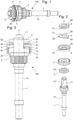
- a friction system 100 according to the invention is shown.
- This system comprises an axis 1 arranged to be mounted in a clockwork movement, the axis may comprise parts with sections 10, 11 of different diameters
- the axis 1 carries a toothed member 3, here a pinion, mounted freely in rotation on the axis 1.
- this toothed member 3 can be a wheel.
- the axis 1 can also carry several toothed members, and can take a large number of known forms according to the needs of those skilled in the art.
- the system 100 also comprises a second fixed element 4, the toothed element being positioned and rotating around the axis 1, between the first fixed element 2 and the second fixed element 4.
- the second fixed element 4 is in the form of a collar comprising a rib 42 of annular shape on its face oriented towards the toothed element 3 forming a annular bearing surface between the toothed element 3 and the second fixed element 4.
- the collar 4 has on its other face an annular peripheral rim 40 forming a skirt, an empty space 43 thus extending between the annular peripheral rim 40 and the center of the collar 4.
- the annular peripheral rim 40 is beveled so as to form a conical bearing surface.
- the axis 1 comprises a bearing surface 12 arranged to cooperate with a flat 41 of the second fixed element 4.
- a bearing surface 12 arranged to cooperate with a flat 41 of the second fixed element 4.
- the system also comprises a third fixed element 6 which is mounted or driven onto the axis 1.
- This third fixed element is in the form of a ring 6, the ring 6 having an excess thickness 60 near the hole 61 by which it is mounted onto the axis 1.
- the excess thickness 60 has a diameter smaller than that of the ring 6 and forms an annular bearing surface 62 for a spring 5.
- the spring 5 is mounted fixed or movable around the axis 1 and is arranged between the second fixed element and the third fixed element.
- the spring 5 is in the form of a flat washer comprising an inner part 51 in the immediate vicinity of the axis 1 which bears against the third fixed element 6, and more precisely bears against the excess thickness 6, and an outer peripheral part bearing elastically against the conical surface 40 of the skirt 4.
- the spring 5 is in the form of a flat washer, which then deforms elastically when it is stressed between the second fixed element 4 and the third fixed element 5.
- the use of a flat washer is particularly advantageous because the use of a part plane makes it easier to reproduce the latter, particularly in relation to a curved element for example.
- the spring 5 comprises at least two lugs 50 arranged at the outer periphery of the washer and are arranged to rest in elastic support against the conical support surface 40 of the second fixed element 4.
- the spring 5 makes it possible to form a kinematic connection both between the first fixed element 2 and the toothed member 3, and between the second fixed element 4 and the toothed member 3 up to a predefined friction torque.
- the spring 5 has three lugs so as to provide better distribution of forces and also facilitate the deformation of the spring.
- the lugs 50 are distributed on the washer 5 at identical angular distances to provide a good distribution of the bearing force on the annular peripheral edge 40 of the collar 4.
- the three lugs are arranged at 120° from each other. In the case where the number of lugs is greater, for example five lugs, the latter would be arranged at 72° from each other.
- the friction torque can be perfectly adjusted by precisely driving the ring 6 onto the axis 1 against the spring 5, the elastic force exerted by the spring 5 on the fixed element 4 making it possible to obtain a very precise friction torque.
- the lugs 50 located on the outer periphery of the spring 5 and the inner part 51 are located in two different planes, the assembly causing the spring 5 to flex in order to constrain it between the ring 6 and the collar 4.
- the constraint of the spring 5 can therefore be modified by acting on the gap between the planes of the support surfaces 62 and 40, by moving the ring 6 on the axis 1, and consequently the friction torque that the system can undergo before the toothed member 3 pivots relative to the axis 1.
- Such an arrangement thus allows an extremely simple and easily reproducible adjustment.
- the invention also relates to a watch movement comprising a friction system according to the invention.
Landscapes
- Physics & Mathematics (AREA)
- General Physics & Mathematics (AREA)
- Micromachines (AREA)
- Mechanical Operated Clutches (AREA)
- Gears, Cams (AREA)
Priority Applications (4)
| Application Number | Priority Date | Filing Date | Title |
|---|---|---|---|
| EP23220075.8A EP4575662A1 (de) | 2023-12-22 | 2023-12-22 | Reibungssystem für uhrwerk |
| US18/921,067 US20250208570A1 (en) | 2023-12-22 | 2024-10-21 | Friction system for a horological movement |
| JP2024198253A JP7799008B2 (ja) | 2023-12-22 | 2024-11-13 | 時計ムーブメントのための摩擦システム |
| CN202411838752.5A CN120195952A (zh) | 2023-12-22 | 2024-12-13 | 用于钟表机芯的摩擦系统 |
Applications Claiming Priority (1)
| Application Number | Priority Date | Filing Date | Title |
|---|---|---|---|
| EP23220075.8A EP4575662A1 (de) | 2023-12-22 | 2023-12-22 | Reibungssystem für uhrwerk |
Publications (1)
| Publication Number | Publication Date |
|---|---|
| EP4575662A1 true EP4575662A1 (de) | 2025-06-25 |
Family
ID=89322281
Family Applications (1)
| Application Number | Title | Priority Date | Filing Date |
|---|---|---|---|
| EP23220075.8A Pending EP4575662A1 (de) | 2023-12-22 | 2023-12-22 | Reibungssystem für uhrwerk |
Country Status (4)
| Country | Link |
|---|---|
| US (1) | US20250208570A1 (de) |
| EP (1) | EP4575662A1 (de) |
| JP (1) | JP7799008B2 (de) |
| CN (1) | CN120195952A (de) |
Citations (2)
| Publication number | Priority date | Publication date | Assignee | Title |
|---|---|---|---|---|
| US3731481A (en) * | 1971-03-27 | 1973-05-08 | Citizen Watch Co Ltd | Time-setting device for electric timepiece |
| JPS5321249U (de) * | 1976-08-02 | 1978-02-22 | Jeco Kk |
Family Cites Families (2)
| Publication number | Priority date | Publication date | Assignee | Title |
|---|---|---|---|---|
| JPS5733223Y2 (de) * | 1977-02-25 | 1982-07-22 | ||
| CH625382B (de) | 1978-12-08 | Bulova Watch Co Inc | Zeigeruhr, insbesondere armbanduhr. |
-
2023
- 2023-12-22 EP EP23220075.8A patent/EP4575662A1/de active Pending
-
2024
- 2024-10-21 US US18/921,067 patent/US20250208570A1/en active Pending
- 2024-11-13 JP JP2024198253A patent/JP7799008B2/ja active Active
- 2024-12-13 CN CN202411838752.5A patent/CN120195952A/zh active Pending
Patent Citations (2)
| Publication number | Priority date | Publication date | Assignee | Title |
|---|---|---|---|---|
| US3731481A (en) * | 1971-03-27 | 1973-05-08 | Citizen Watch Co Ltd | Time-setting device for electric timepiece |
| JPS5321249U (de) * | 1976-08-02 | 1978-02-22 | Jeco Kk |
Also Published As
| Publication number | Publication date |
|---|---|
| US20250208570A1 (en) | 2025-06-26 |
| JP7799008B2 (ja) | 2026-01-14 |
| CN120195952A (zh) | 2025-06-24 |
| JP2025100364A (ja) | 2025-07-03 |
Similar Documents
| Publication | Publication Date | Title |
|---|---|---|
| EP1738229B1 (de) | Krone für eine uhr mit einer entriegelungseinrichtung | |
| EP1850193B1 (de) | Verfahren zur Einpressung eines Teils in ein anderes Teil | |
| EP3396470A1 (de) | Mechanische bremsvorrichtung für drehteil einer uhr | |
| CH718124B1 (fr) | Dispositif à ressort-spiral pour mécanisme résonateur d'horlogerie muni de moyens d'ajustement de la rigidité. | |
| EP3719583A1 (de) | Mechanische bremsvorrichtung für triebfeder einer uhr | |
| EP3907564B1 (de) | Indexierungselement für uhren | |
| EP4078297A1 (de) | Uhranzeigemechanismus | |
| CH679823B5 (de) | ||
| CH721471A2 (fr) | Système à friction pour mouvement d'horlogerie et procédé d'assemblage d'un tel système | |
| EP3293585B1 (de) | Spiralklötzchenträger und regulierungsverfahren der position eines spiralklötzchens in einem solchen spiralklötzchenträger | |
| EP3772673A1 (de) | Indexierungselement für uhren | |
| EP4692957A1 (de) | Reibungssystem für uhrwerk | |
| CH717059A2 (fr) | Masselotte de réglage. | |
| CH712197B1 (fr) | Système à friction pour mouvement d'horlogerie et son procédé d'assemblage. | |
| CH716423B1 (fr) | Ensemble limiteur d'horlogerie pour une montre comportant au moins un tourbillon ou un carrousel. | |
| EP4123391B1 (de) | Uhrenkomponente zur befestigung auf einer welle und verfahren | |
| CH716036A2 (fr) | Mécanisme d'horlogerie comportant un dispositif de freinage mécanique pour mobile horloger. | |
| EP4492156A1 (de) | Uhrvorrichtung | |
| EP4428628B1 (de) | Vorrichtung zur autonomen einstellung der aktiven länge einer spiralfeder | |
| EP4575657A1 (de) | Vorrichtung zur zeiteinstellung einer uhrwerke | |
| CH721465A2 (fr) | Dispositif de mise à l'heure d'un mouvement horloger | |
| EP3770695B1 (de) | Anschlagkäfig für uhr mit käfiganschlagblatt | |
| CH717383A2 (fr) | Elément d'indexation d'horlogerie. | |
| CH720580A2 (fr) | Dispositif de réglage autonome de la longueur active d'un spiral | |
| EP4254075A1 (de) | Versetzte steuerungsvorrichtung eines uhrwerks einer armbanduhr und diese steuerungsvorrichtung umfassende armbanduhr |
Legal Events
| Date | Code | Title | Description |
|---|---|---|---|
| PUAI | Public reference made under article 153(3) epc to a published international application that has entered the european phase |
Free format text: ORIGINAL CODE: 0009012 |
|
| STAA | Information on the status of an ep patent application or granted ep patent |
Free format text: STATUS: THE APPLICATION HAS BEEN PUBLISHED |
|
| AK | Designated contracting states |
Kind code of ref document: A1 Designated state(s): AL AT BE BG CH CY CZ DE DK EE ES FI FR GB GR HR HU IE IS IT LI LT LU LV MC ME MK MT NL NO PL PT RO RS SE SI SK SM TR |
|
| P01 | Opt-out of the competence of the unified patent court (upc) registered |
Free format text: CASE NUMBER: APP_30467/2025 Effective date: 20250625 |
|
| STAA | Information on the status of an ep patent application or granted ep patent |
Free format text: STATUS: REQUEST FOR EXAMINATION WAS MADE |
|
| 17P | Request for examination filed |
Effective date: 20260102 |
|
| GRAP | Despatch of communication of intention to grant a patent |
Free format text: ORIGINAL CODE: EPIDOSNIGR1 |
|
| STAA | Information on the status of an ep patent application or granted ep patent |
Free format text: STATUS: GRANT OF PATENT IS INTENDED |