EP4575679A1 - Vorrichtung zum trennen von aufgewunden spiralfedern nach einem entspannungszyklus und verfahren zur herstellung einer spiralfeder mit einer solchen vorrichtung - Google Patents
Vorrichtung zum trennen von aufgewunden spiralfedern nach einem entspannungszyklus und verfahren zur herstellung einer spiralfeder mit einer solchen vorrichtung Download PDFInfo
- Publication number
- EP4575679A1 EP4575679A1 EP23218286.5A EP23218286A EP4575679A1 EP 4575679 A1 EP4575679 A1 EP 4575679A1 EP 23218286 A EP23218286 A EP 23218286A EP 4575679 A1 EP4575679 A1 EP 4575679A1
- Authority
- EP
- European Patent Office
- Prior art keywords
- spiral springs
- spiral
- vibrating table
- manufacturing
- strapped
- Prior art date
- Legal status (The legal status is an assumption and is not a legal conclusion. Google has not performed a legal analysis and makes no representation as to the accuracy of the status listed.)
- Pending
Links
Images
Classifications
-
- G—PHYSICS
- G04—HOROLOGY
- G04D—APPARATUS OR TOOLS SPECIALLY DESIGNED FOR MAKING OR MAINTAINING CLOCKS OR WATCHES
- G04D3/00—Watchmakers' or watch-repairers' machines or tools for working materials
-
- B—PERFORMING OPERATIONS; TRANSPORTING
- B21—MECHANICAL METAL-WORKING WITHOUT ESSENTIALLY REMOVING MATERIAL; PUNCHING METAL
- B21F—WORKING OR PROCESSING OF METAL WIRE
- B21F3/00—Coiling wire into particular forms
- B21F3/08—Coiling wire into particular forms to flat spiral
-
- B—PERFORMING OPERATIONS; TRANSPORTING
- B65—CONVEYING; PACKING; STORING; HANDLING THIN OR FILAMENTARY MATERIAL
- B65G—TRANSPORT OR STORAGE DEVICES, e.g. CONVEYORS FOR LOADING OR TIPPING, SHOP CONVEYOR SYSTEMS OR PNEUMATIC TUBE CONVEYORS
- B65G27/00—Jigging conveyors
- B65G27/10—Applications of devices for generating or transmitting jigging movements
- B65G27/16—Applications of devices for generating or transmitting jigging movements of vibrators, i.e. devices for producing movements of high frequency and small amplitude
-
- B—PERFORMING OPERATIONS; TRANSPORTING
- B65—CONVEYING; PACKING; STORING; HANDLING THIN OR FILAMENTARY MATERIAL
- B65G—TRANSPORT OR STORAGE DEVICES, e.g. CONVEYORS FOR LOADING OR TIPPING, SHOP CONVEYOR SYSTEMS OR PNEUMATIC TUBE CONVEYORS
- B65G47/00—Article or material-handling devices associated with conveyors; Methods employing such devices
- B65G47/22—Devices influencing the relative position or the attitude of articles during transit by conveyors
-
- G—PHYSICS
- G04—HOROLOGY
- G04B—MECHANICALLY-DRIVEN CLOCKS OR WATCHES; MECHANICAL PARTS OF CLOCKS OR WATCHES IN GENERAL; TIME PIECES USING THE POSITION OF THE SUN, MOON OR STARS
- G04B17/00—Mechanisms for stabilising frequency
- G04B17/04—Oscillators acting by spring tension
- G04B17/06—Oscillators with hairsprings, e.g. balance
- G04B17/066—Manufacture of the spiral spring
-
- G—PHYSICS
- G04—HOROLOGY
- G04B—MECHANICALLY-DRIVEN CLOCKS OR WATCHES; MECHANICAL PARTS OF CLOCKS OR WATCHES IN GENERAL; TIME PIECES USING THE POSITION OF THE SUN, MOON OR STARS
- G04B17/00—Mechanisms for stabilising frequency
- G04B17/20—Compensation of mechanisms for stabilising frequency
- G04B17/22—Compensation of mechanisms for stabilising frequency for the effect of variations of temperature
- G04B17/227—Compensation of mechanisms for stabilising frequency for the effect of variations of temperature composition and manufacture of the material used
-
- G—PHYSICS
- G04—HOROLOGY
- G04D—APPARATUS OR TOOLS SPECIALLY DESIGNED FOR MAKING OR MAINTAINING CLOCKS OR WATCHES
- G04D3/00—Watchmakers' or watch-repairers' machines or tools for working materials
- G04D3/0002—Watchmakers' or watch-repairers' machines or tools for working materials for mechanical working other than with a lathe
- G04D3/0035—Watchmakers' or watch-repairers' machines or tools for working materials for mechanical working other than with a lathe for components of the regulating mechanism
- G04D3/0041—Watchmakers' or watch-repairers' machines or tools for working materials for mechanical working other than with a lathe for components of the regulating mechanism for coil-springs
-
- G—PHYSICS
- G04—HOROLOGY
- G04D—APPARATUS OR TOOLS SPECIALLY DESIGNED FOR MAKING OR MAINTAINING CLOCKS OR WATCHES
- G04D3/00—Watchmakers' or watch-repairers' machines or tools for working materials
- G04D3/0074—Watchmakers' or watch-repairers' machines or tools for working materials for treatment of the material, e.g. surface treatment
- G04D3/0089—Watchmakers' or watch-repairers' machines or tools for working materials for treatment of the material, e.g. surface treatment for components of the regulating mechanism, e.g. coil springs
-
- B—PERFORMING OPERATIONS; TRANSPORTING
- B65—CONVEYING; PACKING; STORING; HANDLING THIN OR FILAMENTARY MATERIAL
- B65G—TRANSPORT OR STORAGE DEVICES, e.g. CONVEYORS FOR LOADING OR TIPPING, SHOP CONVEYOR SYSTEMS OR PNEUMATIC TUBE CONVEYORS
- B65G2201/00—Indexing codes relating to handling devices, e.g. conveyors, characterised by the type of product or load being conveyed or handled
- B65G2201/02—Articles
Definitions
- the invention relates to a method of manufacturing a spiral spring intended to equip a balance wheel of a watch movement, as well as a method of manufacturing such a spiral spring.
- the invention relates to a device for separating spiral springs making it possible to facilitate the step of separating the spirals after heat treatment occurring in a method of manufacturing a spiral spring.
- the invention also relates to a method of manufacturing a spiral spring intended to equip a balance wheel of a watch movement.
- spiral springs are also focused on the concern for thermal compensation, in order to guarantee regular chronometric performances. To do this, it is necessary to obtain a coefficient thermoelasticity close to zero. Research is also underway to produce spiral springs with limited sensitivity to magnetic fields.
- the winding operation consists of winding a plurality of rolled wires in a barrel by means of a star or winding spindle so as to form an assembly, or plate, composed of several spiral springs wound in the same plane.
- the set generally consists of between 3 and 6 wires wound in a spiral shape.
- the individual coil springs are then fixed by a relaxation cycle, usually a heat treatment, to give them a final Archimedean spiral shape with a regular pitch, obtain the desired thermoelastic coefficient (TEC), and increase the hardness.
- TEC thermoelastic coefficient
- the next step is to separate the individual nested coil springs.
- This step can become particularly difficult with compensating spiral springs, and even more so with titanium alloy spiral springs, the presence of titanium in the alloy increasing the friction force between the different strapped spiral springs.
- Such a device facilitates the separation of sets of several spiral springs after heat treatment.
- Such a device is particularly effective on compensating spiral springs and in particular spiral springs made of a titanium alloy.
- Vibration in two directions in the same plane makes it possible to generate vibratory movements which are tangent to the coils of the spiral springs.
- Such vibration makes it possible to elastically deform the different coils of spiral springs by following the shape of the coils starting from the center of the assembly and propagating towards the external coils of the spiral springs.
- Another aspect of the invention relates to a method of manufacturing a spiral spring intended to equip a balance wheel of a clockwork movement.
- the manufacturing method notably comprises a step of separating a set of spiral springs which have been strapped and have undergone a relaxation cycle by using the separation device according to the invention.
- the manufacturing method comprises, prior to the separation step, a wrapping step consisting of winding a plurality of rolled wires in a barrel by means of a wrapping star so as to form the set of wrapped spiral springs.
- the manufacturing method comprises, after the strapping step, a step of relaxing the constraints of the set of strapped spiral springs of the assembly.
- the spiral spring is a compensating spring.
- the spiral spring is made from an alloy of niobium and titanium.
- the winding operation consists of winding a plurality of rolled wires into a barrel 2 (illustrated in Figure 6 ) by means of a star, or winding pin so as to form a set, or plate, composed of several wires strapped which are positioned and wound in the same plane. From this stage, the strapped wires are considered to be strapped spiral springs since the shape is definitive and imposed by barrel 2.
- the various strapped springs making up the assembly 10 are then fixed by a relaxation cycle, generally a heat treatment, to give them a final Archimedean spiral shape with a regular pitch.
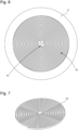
- FIG. 6 schematically illustrates a set 10 of several spiral springs 12 strapped and fixed by a relaxation cycle.
- FIG. 7 schematically illustrates a spiral spring 12 in its final state intended to equip a balance wheel of a clockwork movement.
- the assembly 10 is composed of 3 to 6 spiral springs 12. In the example shown, the assembly 10 comprises 4 spiral springs 12.
- the next step is to separate the various thermally fixed and strapped spiral springs 12 from the assembly 10.
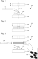
- FIG. 1 shows a schematic representation of an exemplary embodiment of a device 100 for separating an assembly 10 composed of several spiral springs 12 strapped together and thermally fixed.
- the device 100 is described with reference to figures 1 to 4 which schematically illustrate different states of the device 100 during the operation of separating the spiral springs 12.
- the device 100 comprises a support 110 configured to receive and hold the assembly 10 during the separation operation.
- the support 110 comprises a base or a body 111 and a pin 112 extending perpendicular to the general plane formed by the body 111.
- the spindle 112 comprises at its free end a plurality of notches 113.
- the number of notches is greater than or equal to the number of spiral springs making up the assembly 10.
- the spindle 112 comprises four notches 113 distributed uniformly around the circumference of the spindle 112.
- the free end at least partially carrying the notches 113 has a conical profile so as to facilitate the positioning of the assembly 10 or the removal of the different separate spiral springs 12.
- the notches 113 are configured to receive the inner strands 13 of the strapped spiral springs 12 and to hold the assembly 10 at a certain distance from the body 111.
- the different strapped spiral springs 12 of the assembly 10 are held in the device 100 only by the inner strands forming the inner ends of the strapped spiral springs 12, the different turns of the strapped spiral springs 12 being suspended above the body 111 of the support 110.
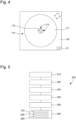
- the device 100 comprises a vibrating table 120 vibrating along two different axes which extend in the same plane, defining a vibration plane P1, illustrated in Figure 4 .
- the two vibration axes are orthogonal to each other.
- the vibrating table 120 has a circular translational movement in the vibration plane P1, as shown in Figure 4 .
- Circular translational movement is understood to mean a plane movement where all the points of the vibrating table 120 have trajectories which are circles of the same radius but with different centers.
- the vibrating table 120 is set into vibration, by mechanical drive, by a motor (not shown).
- the motor is a pneumatic motor or a piezoelectric motor.
- the motor allows the vibrating table 120 to vibrate at a frequency between 1000 Hz and 12000 Hz, preferably between 4000 Hz and 8000 Hz, for example 6000 Hz.
- the amplitude, frequency and vibration power of the vibrating table 120 are parameters that can be modified via a human-machine interface (not shown).
- the vibrating table 120 is integral with the body 111 so that the support 110 is also vibrated in a plane parallel to the vibration plane P1.
- the device 100 further comprises a removable cover 150, or lid, configured to at least partially cover the free end of the spindle 112 to limit the axial movement of the assembly 10 and the separate spiral springs 12, along the longitudinal axis z of the spindle 112, when the support 110 vibrates.
- the removable cover 150 comprises a light or an area of material set back relative to its lower face, i.e. its face facing the vibrating table 120. This light or this withdrawal of material forms a housing 151 configured to receive the free end of the spindle 112, when the removable cover 150 is in the closed position.
- the removable cover 150 is movable between a closed position limiting the movement of the spiral springs along the z axis of the spindle 112 and preventing the removal of the spiral springs 12 from the spindle 112 of the support 110 and an open position allowing the insertion of the set 10 of spiral springs strapped onto the support 110 and also allowing the removal of the spiral springs 12 once separated.
- the removable cover 150 is movable in translation along an axis perpendicular to the vibration plane P1 of the vibrating table 120.
- the translation axis of the removable cover 150 coincides with the longitudinal axis z of the spindle 112.
- the device 100 further comprises an ejector for removing the spiral springs 12 separated from the support 110 in order to prepare a new cycle of separation of an assembly 10.
- the ejector 130 is an air ejector, for example compressed air.
- the device 100 also includes a recovery bin 140 for recovering and collecting the various ejected spiral springs 12.
- the invention also relates to a method 200 for manufacturing a spiral spring intended to equip a balance wheel of a watch movement comprising at least one step 260 of separating the strapped and thermally fixed spiral springs implemented by the device 100 according to the invention.
- the main steps of the manufacturing process 200 are represented with reference to the Figure 5 .
Landscapes
- Engineering & Computer Science (AREA)
- Physics & Mathematics (AREA)
- General Physics & Mathematics (AREA)
- Manufacturing & Machinery (AREA)
- Metallurgy (AREA)
- Mechanical Engineering (AREA)
- Springs (AREA)
- Wire Processing (AREA)
Priority Applications (4)
| Application Number | Priority Date | Filing Date | Title |
|---|---|---|---|
| EP23218286.5A EP4575679A1 (de) | 2023-12-19 | 2023-12-19 | Vorrichtung zum trennen von aufgewunden spiralfedern nach einem entspannungszyklus und verfahren zur herstellung einer spiralfeder mit einer solchen vorrichtung |
| US18/816,189 US20250199475A1 (en) | 2023-12-19 | 2024-08-27 | Device for separating wound in balance springs after an expansion cycle, and method for manufacturing a balance spring comprising a separation step carried out by such a device |
| JP2024157127A JP7738720B2 (ja) | 2023-12-19 | 2024-09-11 | 巻かれたヒゲゼンマイを膨張サイクル後に分離する装置、及びかかる装置によって行われる分離ステップを含むヒゲゼンマイを製造する方法 |
| CN202411467434.2A CN120178644A (zh) | 2023-12-19 | 2024-10-21 | 用于分离游丝的组件的分离装置以及游丝制造方法 |
Applications Claiming Priority (1)
| Application Number | Priority Date | Filing Date | Title |
|---|---|---|---|
| EP23218286.5A EP4575679A1 (de) | 2023-12-19 | 2023-12-19 | Vorrichtung zum trennen von aufgewunden spiralfedern nach einem entspannungszyklus und verfahren zur herstellung einer spiralfeder mit einer solchen vorrichtung |
Publications (1)
| Publication Number | Publication Date |
|---|---|
| EP4575679A1 true EP4575679A1 (de) | 2025-06-25 |
Family
ID=89224452
Family Applications (1)
| Application Number | Title | Priority Date | Filing Date |
|---|---|---|---|
| EP23218286.5A Pending EP4575679A1 (de) | 2023-12-19 | 2023-12-19 | Vorrichtung zum trennen von aufgewunden spiralfedern nach einem entspannungszyklus und verfahren zur herstellung einer spiralfeder mit einer solchen vorrichtung |
Country Status (4)
| Country | Link |
|---|---|
| US (1) | US20250199475A1 (de) |
| EP (1) | EP4575679A1 (de) |
| JP (1) | JP7738720B2 (de) |
| CN (1) | CN120178644A (de) |
Citations (6)
| Publication number | Priority date | Publication date | Assignee | Title |
|---|---|---|---|---|
| DE1279629B (de) * | 1961-12-29 | 1968-10-10 | Siemens Ag | Wickelvorrichtung zum Herstellen von spiralfoermigen Federn aus Metallbaendern |
| CH474099A (fr) * | 1965-06-30 | 1969-07-31 | Lip Sa | Procédé et dispositif pour la fabrication d'un spiral d'appareil horaire |
| FR2029449A1 (de) * | 1969-01-27 | 1970-10-23 | Greiner Rudolf | |
| GB2416408A (en) * | 2003-10-20 | 2006-01-25 | Gideon R Levingston | Balance Wheel, Balance Spring and Other Components and Assemblies for a Mechanical Oscillator System and Methods of Manufacture |
| FR3036813A1 (fr) * | 2015-05-26 | 2016-12-02 | Philippe Rhul | Procede pour fabriquer un spiral d'un mouvement d'horlogerie, equipements de fabrication pour la mise en oeuvre du procede, et spiraux ainsi produits |
| FR3107365A1 (fr) * | 2020-02-17 | 2021-08-20 | Philippe RHUL | « Procédé pour fabriquer un spiral d’un mouvement d’horlogerie, appareil de fabrication pour la mise en œuvre du procédé, et spiraux ainsi produits » |
Family Cites Families (5)
| Publication number | Priority date | Publication date | Assignee | Title |
|---|---|---|---|---|
| JPS5255666A (en) * | 1975-05-28 | 1977-05-07 | Seiko Epson Corp | Method of unfastening balance springs |
| JPS53122459A (en) * | 1977-03-31 | 1978-10-25 | Sendai Seimitsu Zairiyou Kenki | Device for unravelling hair spring |
| EP1921042A1 (de) * | 2006-11-10 | 2008-05-14 | ETA SA Manufacture Horlogère Suisse | Herstellung von mikromechanischer mehrschichtiger Bauteile aus Silizium |
| EP2189854A1 (de) * | 2008-11-21 | 2010-05-26 | Nivarox-FAR S.A. | Verfahren zur Herstellung eines mikromechanischen Bauteils |
| EP4521172A1 (de) * | 2023-09-06 | 2025-03-12 | Nivarox-FAR S.A. | Werkzeug und verfahren zur trennung von spiralfedern nach dem gleiten und wärmebehandlung |
-
2023
- 2023-12-19 EP EP23218286.5A patent/EP4575679A1/de active Pending
-
2024
- 2024-08-27 US US18/816,189 patent/US20250199475A1/en active Pending
- 2024-09-11 JP JP2024157127A patent/JP7738720B2/ja active Active
- 2024-10-21 CN CN202411467434.2A patent/CN120178644A/zh active Pending
Patent Citations (6)
| Publication number | Priority date | Publication date | Assignee | Title |
|---|---|---|---|---|
| DE1279629B (de) * | 1961-12-29 | 1968-10-10 | Siemens Ag | Wickelvorrichtung zum Herstellen von spiralfoermigen Federn aus Metallbaendern |
| CH474099A (fr) * | 1965-06-30 | 1969-07-31 | Lip Sa | Procédé et dispositif pour la fabrication d'un spiral d'appareil horaire |
| FR2029449A1 (de) * | 1969-01-27 | 1970-10-23 | Greiner Rudolf | |
| GB2416408A (en) * | 2003-10-20 | 2006-01-25 | Gideon R Levingston | Balance Wheel, Balance Spring and Other Components and Assemblies for a Mechanical Oscillator System and Methods of Manufacture |
| FR3036813A1 (fr) * | 2015-05-26 | 2016-12-02 | Philippe Rhul | Procede pour fabriquer un spiral d'un mouvement d'horlogerie, equipements de fabrication pour la mise en oeuvre du procede, et spiraux ainsi produits |
| FR3107365A1 (fr) * | 2020-02-17 | 2021-08-20 | Philippe RHUL | « Procédé pour fabriquer un spiral d’un mouvement d’horlogerie, appareil de fabrication pour la mise en œuvre du procédé, et spiraux ainsi produits » |
Also Published As
| Publication number | Publication date |
|---|---|
| JP2025097897A (ja) | 2025-07-01 |
| JP7738720B2 (ja) | 2025-09-12 |
| CN120178644A (zh) | 2025-06-20 |
| US20250199475A1 (en) | 2025-06-19 |
Similar Documents
| Publication | Publication Date | Title |
|---|---|---|
| EP2105807B1 (de) | Monoblockspirale zur Erhöhung der Kurve und ihr Herstellungsverfahren | |
| EP2598952B1 (de) | Kontaktlose kraftübertragung in einem uhrwerk | |
| EP1655642B1 (de) | Spiralfeder der Resonatorunruh | |
| EP2104006B1 (de) | Monoblock-Doppelspirale und ihr Herstellungsverfahren | |
| EP3208667B1 (de) | Magnetisches hemmungsdrehteil eines uhrwerks | |
| WO2007000271A1 (fr) | Piece de micro-mecanique renforcee | |
| EP2288473B1 (de) | Verfahren zum ultraschallkugelstrahlen von turbomaschinenteilen | |
| WO2008135817A2 (fr) | Composant horloger et son procédé de fabrication | |
| EP3623876A1 (de) | Spiralrolle mit nicht kreisförmiger öffnung | |
| EP3759554B1 (de) | Herstellungsverfahren einer spiralfeder | |
| CH721429A2 (fr) | Dispositif pour la séparation de ressorts spiraux estrapadés après un cycle de détente et procédé de fabrication d'un tel ressort spiral | |
| TWI793285B (zh) | 用於生產矽基時計彈簧的方法 | |
| EP3451076A1 (de) | Spiralklötzchenträger für ein mechanisches uhrwerk | |
| EP2717437B1 (de) | Elektromagnetischer Motor für elektronisches Uhrwerk mit Analoganzeige | |
| EP2104007A1 (de) | Monoblockspirale aus Material auf Siliziumbasis und ihr Herstellungsverfahren | |
| EP4121821A1 (de) | Verfahren zur herstellung eines uhrenbauteils auf siliziumbasis | |
| EP2979139B1 (de) | Schwenkbarer zuganker einer uhr | |
| EP3179315A1 (de) | Spiralklötzchenträger mit gesicherter montage | |
| EP2400355A1 (de) | Stoßsicheres System für Uhr | |
| JP7738720B2 (ja) | 巻かれたヒゲゼンマイを膨張サイクル後に分離する装置、及びかかる装置によって行われる分離ステップを含むヒゲゼンマイを製造する方法 | |
| FR3107365A1 (fr) | « Procédé pour fabriquer un spiral d’un mouvement d’horlogerie, appareil de fabrication pour la mise en œuvre du procédé, et spiraux ainsi produits » | |
| FR2887919A1 (fr) | Rotor de turbomachine comprenant au moins un disque renforce par un anneau composite | |
| EP4019459B1 (de) | Verfahren zur herstellung einer thermokompensierten spiralfeder | |
| CH718217A2 (fr) | Procédé de fabrication d'un ressort spiral thermocompensé. | |
| HK40121674A (zh) | 用於分离游丝的组件的分离装置以及游丝制造方法 |
Legal Events
| Date | Code | Title | Description |
|---|---|---|---|
| PUAI | Public reference made under article 153(3) epc to a published international application that has entered the european phase |
Free format text: ORIGINAL CODE: 0009012 |
|
| STAA | Information on the status of an ep patent application or granted ep patent |
Free format text: STATUS: THE APPLICATION HAS BEEN PUBLISHED |
|
| AK | Designated contracting states |
Kind code of ref document: A1 Designated state(s): AL AT BE BG CH CY CZ DE DK EE ES FI FR GB GR HR HU IE IS IT LI LT LU LV MC ME MK MT NL NO PL PT RO RS SE SI SK SM TR |
|
| STAA | Information on the status of an ep patent application or granted ep patent |
Free format text: STATUS: REQUEST FOR EXAMINATION WAS MADE |
|
| GRAP | Despatch of communication of intention to grant a patent |
Free format text: ORIGINAL CODE: EPIDOSNIGR1 |
|
| STAA | Information on the status of an ep patent application or granted ep patent |
Free format text: STATUS: GRANT OF PATENT IS INTENDED |
|
| 17P | Request for examination filed |
Effective date: 20260102 |
|
| INTG | Intention to grant announced |
Effective date: 20260203 |
|
| GRAS | Grant fee paid |
Free format text: ORIGINAL CODE: EPIDOSNIGR3 |
|
| GRAA | (expected) grant |
Free format text: ORIGINAL CODE: 0009210 |
|
| STAA | Information on the status of an ep patent application or granted ep patent |
Free format text: STATUS: THE PATENT HAS BEEN GRANTED |