EP4575973A2 - Upsampling - Google Patents
Upsampling Download PDFInfo
- Publication number
- EP4575973A2 EP4575973A2 EP24220664.7A EP24220664A EP4575973A2 EP 4575973 A2 EP4575973 A2 EP 4575973A2 EP 24220664 A EP24220664 A EP 24220664A EP 4575973 A2 EP4575973 A2 EP 4575973A2
- Authority
- EP
- European Patent Office
- Prior art keywords
- pixels
- input
- upsampled
- kernel
- input pixels
- Prior art date
- Legal status (The legal status is an assumption and is not a legal conclusion. Google has not performed a legal analysis and makes no representation as to the accuracy of the status listed.)
- Pending
Links
Images








Classifications
-
- H—ELECTRICITY
- H04—ELECTRIC COMMUNICATION TECHNIQUE
- H04N—PICTORIAL COMMUNICATION, e.g. TELEVISION
- H04N19/00—Methods or arrangements for coding, decoding, compressing or decompressing digital video signals
- H04N19/50—Methods or arrangements for coding, decoding, compressing or decompressing digital video signals using predictive coding
- H04N19/59—Methods or arrangements for coding, decoding, compressing or decompressing digital video signals using predictive coding involving spatial sub-sampling or interpolation, e.g. alteration of picture size or resolution
-
- G—PHYSICS
- G06—COMPUTING OR CALCULATING; COUNTING
- G06T—IMAGE DATA PROCESSING OR GENERATION, IN GENERAL
- G06T3/00—Geometric image transformations in the plane of the image
- G06T3/40—Scaling of whole images or parts thereof, e.g. expanding or contracting
- G06T3/4053—Scaling of whole images or parts thereof, e.g. expanding or contracting based on super-resolution, i.e. the output image resolution being higher than the sensor resolution
-
- G—PHYSICS
- G06—COMPUTING OR CALCULATING; COUNTING
- G06T—IMAGE DATA PROCESSING OR GENERATION, IN GENERAL
- G06T1/00—General purpose image data processing
- G06T1/20—Processor architectures; Processor configuration, e.g. pipelining
-
- G—PHYSICS
- G06—COMPUTING OR CALCULATING; COUNTING
- G06T—IMAGE DATA PROCESSING OR GENERATION, IN GENERAL
- G06T3/00—Geometric image transformations in the plane of the image
- G06T3/40—Scaling of whole images or parts thereof, e.g. expanding or contracting
- G06T3/4007—Scaling of whole images or parts thereof, e.g. expanding or contracting based on interpolation, e.g. bilinear interpolation
-
- G—PHYSICS
- G06—COMPUTING OR CALCULATING; COUNTING
- G06T—IMAGE DATA PROCESSING OR GENERATION, IN GENERAL
- G06T3/00—Geometric image transformations in the plane of the image
- G06T3/40—Scaling of whole images or parts thereof, e.g. expanding or contracting
- G06T3/4046—Scaling of whole images or parts thereof, e.g. expanding or contracting using neural networks
-
- G—PHYSICS
- G06—COMPUTING OR CALCULATING; COUNTING
- G06T—IMAGE DATA PROCESSING OR GENERATION, IN GENERAL
- G06T5/00—Image enhancement or restoration
- G06T5/10—Image enhancement or restoration using non-spatial domain filtering
-
- G—PHYSICS
- G06—COMPUTING OR CALCULATING; COUNTING
- G06T—IMAGE DATA PROCESSING OR GENERATION, IN GENERAL
- G06T5/00—Image enhancement or restoration
- G06T5/60—Image enhancement or restoration using machine learning, e.g. neural networks
-
- G—PHYSICS
- G06—COMPUTING OR CALCULATING; COUNTING
- G06T—IMAGE DATA PROCESSING OR GENERATION, IN GENERAL
- G06T5/00—Image enhancement or restoration
- G06T5/73—Deblurring; Sharpening
-
- H—ELECTRICITY
- H04—ELECTRIC COMMUNICATION TECHNIQUE
- H04N—PICTORIAL COMMUNICATION, e.g. TELEVISION
- H04N19/00—Methods or arrangements for coding, decoding, compressing or decompressing digital video signals
- H04N19/10—Methods or arrangements for coding, decoding, compressing or decompressing digital video signals using adaptive coding
- H04N19/102—Methods or arrangements for coding, decoding, compressing or decompressing digital video signals using adaptive coding characterised by the element, parameter or selection affected or controlled by the adaptive coding
- H04N19/117—Filters, e.g. for pre-processing or post-processing
-
- H—ELECTRICITY
- H04—ELECTRIC COMMUNICATION TECHNIQUE
- H04N—PICTORIAL COMMUNICATION, e.g. TELEVISION
- H04N19/00—Methods or arrangements for coding, decoding, compressing or decompressing digital video signals
- H04N19/10—Methods or arrangements for coding, decoding, compressing or decompressing digital video signals using adaptive coding
- H04N19/169—Methods or arrangements for coding, decoding, compressing or decompressing digital video signals using adaptive coding characterised by the coding unit, i.e. the structural portion or semantic portion of the video signal being the object or the subject of the adaptive coding
- H04N19/17—Methods or arrangements for coding, decoding, compressing or decompressing digital video signals using adaptive coding characterised by the coding unit, i.e. the structural portion or semantic portion of the video signal being the object or the subject of the adaptive coding the unit being an image region, e.g. an object
- H04N19/176—Methods or arrangements for coding, decoding, compressing or decompressing digital video signals using adaptive coding characterised by the coding unit, i.e. the structural portion or semantic portion of the video signal being the object or the subject of the adaptive coding the unit being an image region, e.g. an object the region being a block, e.g. a macroblock
-
- H—ELECTRICITY
- H04—ELECTRIC COMMUNICATION TECHNIQUE
- H04N—PICTORIAL COMMUNICATION, e.g. TELEVISION
- H04N19/00—Methods or arrangements for coding, decoding, compressing or decompressing digital video signals
- H04N19/80—Details of filtering operations specially adapted for video compression, e.g. for pixel interpolation
-
- G—PHYSICS
- G06—COMPUTING OR CALCULATING; COUNTING
- G06T—IMAGE DATA PROCESSING OR GENERATION, IN GENERAL
- G06T2207/00—Indexing scheme for image analysis or image enhancement
- G06T2207/20—Special algorithmic details
- G06T2207/20084—Artificial neural networks [ANN]
Definitions
- upsampling can be applied to input pixels representing an image region to determine a block of upsampled pixels, e.g. for super resolution techniques.
- the term 'super resolution' refers to techniques of upsampling an image that enhance the apparent visual quality of the image, e.g. by estimating the appearance of a higher resolution version of the image.
- super resolution is a challenging problem because, for every patch in a lower-resolution input image, there is a very large number of potential higher-resolution patches that could correspond to it. In other words, super resolution techniques are trying to solve an ill-posed problem, since although solutions exist, they are not unique.
- An image generation process may be an image capturing process, e.g. using a camera.
- an image generation process may be an image rendering process in which a computer, e.g. a graphics processing unit (GPU), renders an image of a virtual scene.
- a computer e.g. a graphics processing unit (GPU)
- GPUs may implement any suitable rendering technique, such as rasterization or ray tracing.
- a GPU can render a 960x540 image (i.e. an image with 518,400 pixels arranged into 960 columns and 540 rows) which can then be upsampled by a factor of 2 in both horizontal and vertical dimensions (which is referred to as ⁇ 2x upsampling') to produce a 1920x1080 image (i.e.
- the GPU renders an image with a quarter of the number of pixels. This results in very significant savings (e.g. in terms of latency, power consumption and/or silicon area of the GPU) during rendering and can for example allow a relatively low-performance GPU to render high-quality, high-resolution images within a low power and area budget, provided a suitably efficient and high-quality super-resolution implementation is used to perform the upsampling. In other examples, different upsampling factors (other than 2x) may be applied.
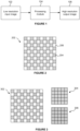
- FIG. 1 illustrates an upsampling process.
- An input image 102 which has a relatively low resolution, is processed by a processing module 104 to produce an output image 106 which has a relatively high resolution.
- the processing module 104 may be implemented as a neural network to upsample the input image 102 to produce the upsampled output image 106.
- Implementing the processing module 104 as a neural network may produce good quality output images, but often requires a high performance computing system (e.g. with large, powerful processing units and memories) to implement the neural network.
- implementing the processing module 104 as a neural network for performing upsampling of images may be unsuitable for reasons of processing time, latency, bandwidth, power consumption, memory usage, silicon area and compute costs. These considerations of efficiency are particularly important in some devices, e.g. small, battery operated devices with limited compute and bandwidth resources, such as mobile phones and tablets.
- Some systems do not use a neural network for performing super resolution on images, and instead use more conventional processing modules. For example, some systems split the problem into two stages: (i) upsampling and (ii) adaptive sharpening.
- the upsampling stage can be performed cheaply, e.g. using bilinear upsampling, and the adaptive sharpening stage can be used to sharpen the image, i.e. reduce the blurring introduced by the upsampling.
- Bilinear upsampling is known in the art and uses linear interpolation of adjacent input pixels in two dimensions to produce output pixels at positions between input pixels.
- a method of applying upsampling to input pixels representing an image region to determine a block of upsampled pixels, wherein the input pixels have locations corresponding to a repeating quincunx arrangement of upsampled pixel locations comprising:
- the one or more weighting parameters may be indicative of relative horizontal and vertical variation of the input pixels within the image region.
- the one or more of the upsampled pixels of the block of upsampled pixels may be determined in accordance with the relative horizontal and vertical variation of the input pixels within the image region indicated by the determined one or more weighting parameters.
- Determining each of said one or more of the upsampled pixels may comprise applying one or more kernels to at least some of the input pixels in accordance with the determined one or more weighting parameters.
- Each of said one or more of the upsampled pixels may be at a respective upsampled pixel location which does not correspond with the location of any of the input pixels.
- the input pixels may be represented in two input blocks.
- One of the two input blocks may comprise the input pixels having locations corresponding to locations within odd rows of the repeating quincunx arrangement of upsampled pixel locations, and the other of the two input blocks may comprise the input pixels having locations corresponding to locations within even rows of the repeating quincunx arrangement of upsampled pixel locations.
- the image region may be part of a current frame within a sequence of frames.
- the input pixels of a first of the input blocks may be rendered for the current frame.
- the input pixels of a second of the input blocks may be determined by performing temporal resampling on pixels of a previous frame using motion vectors.
- Pixels for the previous frame corresponding to the pixel locations of the input pixels of the second input block may have been rendered for the previous frame.
- Said using the determined indications of image gradients to determine the one or more weighting parameters may comprise:
- the processing modules described herein may be embodied in hardware on an integrated circuit.
- a method of manufacturing at an integrated circuit manufacturing system, a processing module.
- an integrated circuit definition dataset that, when processed in an integrated circuit manufacturing system, configures the system to manufacture a processing module.
- a non-transitory computer readable storage medium having stored thereon a computer readable description of a processing module that, when processed in an integrated circuit manufacturing system, causes the integrated circuit manufacturing system to manufacture an integrated circuit embodying a processing module.
- an integrated circuit manufacturing system comprising: a non-transitory computer readable storage medium having stored thereon a computer readable description of the processing module; a layout processing system configured to process the computer readable description so as to generate a circuit layout description of an integrated circuit embodying the processing module; and an integrated circuit generation system configured to manufacture the processing module according to the circuit layout description.
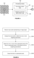
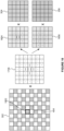
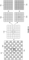
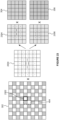
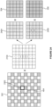
- the input pixels 202 are processed, as described herein, to determine a block of upsampled pixels which includes an upsampled pixel at some of the upsampled pixel locations shown in Figure 2 which do not correspond to the location of an input pixel.
- the density of upsampled pixels is double the density of input pixels.
- the use of the repeating quincunx arrangement means that output pixel locations that do not correspond to the location of an input pixel (shown without hatching in Figure 2 ) are horizontally adjacent to two output pixel locations that do correspond to the location of an input pixel (shown with hatching in Figure 2 ) and are vertically adjacent to two output pixel locations that do correspond to the location of an input pixel (shown with hatching in Figure 2 ).
- the indication of the weighting parameters may be some but not all of the weighting parameters, wherein the other weighting parameter(s) can be derived from the weighting parameter(s) that are explicitly included in the indication.
- weighting parameter(s) rather than pixel values is that it is more straightforward to combine such a network trained for unsharpened upsampling with a tuneable adaptive sharpening algorithm (as explained below) without introducing wasteful intermediate buffering.
- Some of the super resolution techniques described in examples herein implement upsampling and adaptive sharpening.
- a memory for storing an upsampled image prior to applying adaptive sharpening is not needed.
- the upsampling and sharpening processes can be combined into a unified process. This can be achieved by applying a sharp upsampling kernel to the input pixels, where the sharp upsampling kernel represents a result of convolving an interpolation kernel with a sharpening kernel.
- the sharp upsampling kernel can be deconstructed into a first set of one or more kernels to be applied to the first input block and a second set of one or more kernels to be applied to the second input block.
- the weight for the sharp upsampled pixels is chosen to be larger than the weight for the non-sharp upsampled pixels so that the output pixels are similar to the sharp upsampled pixels.
- the weight for the sharp upsampled pixels is chosen to be smaller than the weight for the non-sharp upsampled pixels so that the output pixels are similar to the non-sharp upsampled pixels. In this way, more sharpening is applied to regions of low contrast in the image than to regions of high contrast in the image.
- the format of the pixels could be different in different examples.
- the pixels could be in YUV format (in which each pixel has a value in each of Y, U and V channels), and upsampling may be applied to each of the Y, U and V channels separately.
- the upsampling described herein may be applied to just the Y channel, with the upsampling of the U and V channels being performed in a simpler manner, e.g. using bilinear interpolation.
- the upsampling described herein may be applied to each of the Y, U and V channels.
- results from some or all of the computation e.g.
- the U and V channels may or may not be adaptively sharpened and/or upsampled taking account of local context. If the input pixel data is in RGB format then it could be converted into YUV format (e.g. using a known colour space conversion technique) and then processed as data in Y, U and V channels.
- Figure 4 shows a processing module 402 configured to apply upsampling to input pixels 302, which represent an image region, to determine a block of upsampled pixels 404, e.g. for use in implementing a super resolution technique.
- the block of upsampled pixels 404 represents a location within the image region indicated with the square 410 in Figure 4 .
- the input pixels 302 have locations corresponding to a 10x10 block of upsampled pixel locations
- the block of upsampled pixels 404 is a 2x2 block of upsampled pixels representing the central 2x2 portion of the 10x10 block of upsampled pixel locations.
- the processing module 402 comprises pixel determination logic 406 and weighting parameter determination logic 408.
- the logic of the processing module 402 may be implemented in hardware, software, or a combination thereof.
- a hardware implementation normally provides for a reduced latency and power consumption and higher throughput compared to a software implementation, at the cost of inflexibility of operation.
- the processing module 402 is likely to be used in the same manner a large number of times on each image being upsampled, and since latency is very important in, for example, real time super resolution applications, it is likely that implementing the logic of the processing module 402 in hardware (e.g. in fixed function circuitry) will be preferable to implementing the logic in software.
- a software implementation is still possible and may be preferable in some situations (for example, where there is insufficient microchip area to include additional fixed-function hardware).
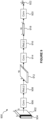
- a method of using the processing module 402 to apply upsampling to the input pixels 302 to determine the block of upsampled pixels 404, e.g. for use in implementing a super resolution technique, is described with reference to the flow chart of Figure 5 .
- step S502 the input pixels 302 are received at the processing module 402.
- the input pixels 302 are represented in two input blocks 304 and 306, as shown in Figure 3 .
- the input pixels are not necessarily represented in two input blocks, e.g. they may be represented in a single block.
- the input pixels 302 have locations corresponding to a repeating quincunx arrangement (or 'chequer board pattern') of upsampled pixel locations, wherein the first input block 304 ( ⁇ input block 1') comprises the input pixels having locations corresponding to locations within odd rows of the repeating quincunx arrangement of upsampled pixel locations (illustrated with line hatching in Figure 3 ), and the second input block 306 ( ⁇ input block 2') comprises the input pixels having locations corresponding to locations within even rows of the repeating quincunx arrangement of upsampled pixel locations (illustrated with cross-hatching in Figure 3 ).
- the input blocks can be considered to be low resolution representations of the image region represented by the input pixels.
- each of the input blocks is a 5x5 block of input pixels
- the block of upsampled pixels is a 2x2 block of upsampled pixels
- the input blocks and the block of upsampled pixels may have different shapes and/or sizes.
- a sequence of frames may be rendered, e.g. representing images of a scene at a sequence of time instances. For example, this may be useful for rendering images for a computer game as a user interacts with a scene.
- the input pixels of just one of the input blocks (304 or 306) are rendered, with the input block that is rendered alternating over the sequence of frames.
- a current frame will be very similar to a previous frame (e.g. the immediately preceding frame), and a process of temporal resampling can be performed to estimate some of the input pixels for the current frame based on the rendered pixels of the previous frame.
- the number of input pixels that are rendered by a GPU for each frame is a quarter of the number of pixels in the final (upsampled) image, which allows the GPU to have even further reduced latency, power consumption and/or silicon area compared to a GPU that renders half of the pixels of the final image for each frame.
- the weighting parameter determination logic 408 might output an indication of a single weighting parameter, e.g. a , and this can be used to determine the second weighting parameter, b , as 1 - a.
- An indication of the one or more weighting parameters is provided to the pixel determination logic 406. Further details of the way in which the weighting parameter determination logic 408 determines the one or more weighting parameters in various examples are given below.
- step S506 the pixel determination logic 406 determines one or more of the upsampled pixels of the block of upsampled pixels 404 in accordance with the directionality of filtering to be applied (e.g. in accordance with the relative horizontal and vertical variation of the input pixels within the image region) indicated by the determined one or more weighting parameters.
- the weighting parameter(s) are indicative of the relative horizontal and vertical variation of the input pixels within the image region, but it is to be understood that this is just one example, and that more generally the weighting parameter(s) are indicative of a directionality of filtering to be applied when upsampling is applied to the input pixels within the image region.
- Figure 6 is a flow chart showing how the pixel determination logic 406 can determine an unsharpened upsampled pixel in step S506 in accordance with the relative horizontal and vertical variation of the input pixels within the image region.
- Figure 7 shows a portion of the input pixels 702 and illustrates how the location of a block of upsampled pixels 706 relates to the locations of the input pixels 704.
- Each of the upsampled pixels that is determined in accordance with the relative horizontal and vertical variation of the input pixels within the image region, in step S506, is at a respective upsampled pixel location which does not correspond with the location of any of the input pixels.
- the top right and the bottom left upsampled pixel in the block of upsampled pixels are determined in step S506 in accordance with the relative horizontal and vertical variation of the input pixels within the image region.
- the input pixels having locations corresponding to the repeating quincunx arrangement of upsampled pixel locations are used as the upsampled pixels at those upsampled pixel locations of the block of upsampled pixels (e.g. the input pixels at the top left and bottom right locations of the block of upsampled pixels 706 are "passed through” to the corresponding locations in the output block). If sharpening is applied then some processing is performed on the input pixels to determine all of the upsampled pixels in the block of upsampled pixels, as described in more detail below with reference to Figures 13 to 26 .
- the input pixels 704 are represented in two input blocks (e.g. 304 and 306).
- input pixels 704 1,1 , 704 1,2 , 704 1,3 and 704 1,4 which are shown with line hatching, are part of the first input block 304; whereas input pixels 704 2,1 , 704 2,2 , 704 2,3 and 704 2,4 , which are shown with cross hatching, are part of the second input block 306.
- step S506 of determining each of said one or more of the upsampled pixels comprises applying one or more kernels to at least some of the input pixels in accordance with the determined one or more weighting parameters.
- the pixel determination logic 406 applies one or more first kernels (which may be referred to as horizontal kernels) to at least a first subset of the input pixels to determine a horizontal component.
- a kernel of [0.5,0.5] can be applied to the input pixels which are horizontally adjacent and either side of the upsampled pixel location for which an upsampled pixel is being determined.
- step S602 when step S602 is performed for the upsampled pixel denoted "TR” in Figure 7 then the horizontal kernel is applied to pixels 704 1,1 and 704 1,2 from input block 1.
- step S602 is performed for the upsampled pixel denoted "BL” in Figure 7 then the horizontal kernel is applied to pixels 704 2,3 and 704 2,4 from input block 2.
- step S604 the pixel determination logic 406 applies one or more second kernels (which may be referred to as vertical kernels) to at least a second subset of the input pixels to determine a vertical component.
- a kernel of 0.5 0.5 can be applied to the input pixels which are vertically adjacent and either side of the upsampled pixel location for which an upsampled pixel is being determined.
- the vertical kernel is applied to pixels 704 2,2 and 704 2,4 from input block 2.
- step S604 is performed for the upsampled pixel denoted "BL” in Figure 7 then the vertical kernel is applied to pixels 704 1,1 and 704 1,3 from input block 1.
- each of the one or more of the upsampled pixels for which step S506 is performed has two horizontally adjacent pixels which are both from the same input block (either from input block 1 or input block 2) and has two vertically adjacent pixels which are both from the other input block (either from input block 2 or input block 1). It is also noted that steps S602 and S604 may be performed in any order, e.g. sequentially, or may be performed in parallel.
- the pixel determination logic 406 combines the determined horizontal and vertical components, such that each of said one or more of the upsampled pixels is determined in accordance with the relative horizontal and vertical variation of the input pixels within the image region as indicated by the one or more weighting parameters determined in step S504.
- the pixel determination logic 406 multiplies the horizontal component (determined in step S602) by a first of the weighting parameters, a , to determine a weighted horizontal component.
- step S608 the pixel determination logic 406 multiplies the vertical component (determined in step S604) by a second of the weighting parameters, b , to determine a weighted vertical component.
- Steps S606 and S608 may be performed in any order, e.g. sequentially, or may be performed in parallel.
- step S610 the pixel determination logic 406 sums the weighted horizontal component and the weighted vertical component to determine the upsampled pixel.
- the kernels applied in S602 and S604 may be multiplied by the first and second weighting parameters respectively before, or during, application to the input pixels. This is expected to be less power- and area-efficient in hardware than the method described with reference to Figure 6 , since the application of kernels of Figures 8a and 8b may be obtained using only cheap fixed bit shifts and additions, and the number of variable multiplies required is considerably lower.
- Figure 8a shows a 3x3 kernel 802 (which may be implemented as a 1x3 kernel) which can be applied to the input pixels 702 to represent the effect of performing steps S602 and S606 for an upsampled pixel location being determined.
- the kernel 802 could be centred on the upsampled pixel being determined and applied to the input pixels 702 such that the result would be given by the dot product a 2 a 2 . h , where h is a vector of the horizontally adjacent pixel values.
- h [ p 1 , 1 , p 1,2 ], where p 1,1 is the value of input pixel 704 1,1 and p 1,2 is the value of input pixel 704 1,2 .
- h [ p 2,3 , p 2,4 ], where p 2,3 is the value of input pixel 704 2,3 and p 2,4 is the value of input pixel 704 2,4 .
- Figure 8b shows a 3x3 kernel 804 (which may be implemented as a 3x1 kernel) which can be applied to the input pixels 702 to represent the effect of performing steps S604 and S608 for an upsampled pixel location being determined.
- the kernel 804 could be centred on the upsampled pixel being determined and applied to the input pixels 702 such that the result would be given by the dot product b 2 b 2 .
- v where v is a vector of the vertically adjacent pixel values.
- v [ p 2,2 , p 2,4 ], where p 2,2 is the value of input pixel 704 2,2 and p 2,4 is the value of input pixel 704 2,4 .
- v [ p 1,1 , p 1,3 ], where p 1,1 is the value of input pixel 704 1,1 and p 1,3 is the value of input pixel 704 1,3 .
- steps S602 to S610 can be summarised as determining the upsampled pixels denoted TR and BL as the sum of dot products: a 2 a 2 . h + b 2 b 2 . v , where h and v are vectors of adjacent pixel values as described above for the TR and BL pixels respectively.
- the values of the weighting parameters, a and b are set in dependence on the local context, such that by determining the upsampled pixels in step S506 in accordance with the determined weighting parameters the upsampled pixels are determined in accordance with the relative horizontal and vertical variation of the input pixels within the image region.
- the weighting parameters can be used to reduce artefacts and blurring over anisotropic features (e.g. edges) in the image, which may otherwise result from an upsampling process.
- the weighting parameter determination logic 408 analyses the input pixels in step S504 to determine the one or more weighting parameters.
- the one or more weighting parameters are determined for the particular image region being processed, such that different weighting parameters can be used in the upsampling process for different image regions.
- the weighting parameters can be adapted to suit the particular local context of the image region for which upsampled pixels are being determined. This allows suitable weighting parameters to be used for different image regions based on the different anisotropic image features present in the different image regions.
- the weighting parameter determination logic 408 of the processing module 402 may comprise an implementation of a neural network for determining the weighting parameter(s).
- Figure 9 illustrates an implementation of a convolutional neural network 900 configured to output an indication of the weighting parameter(s) for use in applying upsampling to input pixels representing an image region to determine a block of upsampled pixels.
- the implementation of the neural network 900 may be implemented on any suitable hardware, e.g. a GPU or a neural network accelerator (NNA), or as fixed-function hardware with predetermined, fixed weights (i.e.
- the implementation of the neural network 900 is configured to receive the input pixels 902, process the input pixels to determine an indication of the one or more weighting parameters, and output the determined indication of the one or more weighting parameters for use in applying upsampling to the input pixels representing the image region to determine a block of upsampled pixels.
- the input pixels are represented in two input blocks, wherein one of the two input blocks comprises the input pixels having locations corresponding to locations within odd rows of a repeating quincunx arrangement of upsampled pixel locations, and the other of the two input blocks comprises the input pixels having locations corresponding to locations within even rows of the repeating quincunx arrangement of upsampled pixel locations.
- each of the input blocks is a 5x5 block of input pixels, such that the input pixels 902 are shown as a 5x5x2 array to indicate that the input pixels are organised as two 5x5 input blocks of input pixels.
- the neural network is trained to output an indication of the one or more weighting parameters to be indicative of relative horizontal and vertical variation of the input pixels within the image region, rather than attempting to train the neural network to output the upsampled pixels themselves.
- a neural network is well suited to determining suitable weighting parameters to represent the relative horizontal and vertical variation of anisotropic image features within the image region, and this task can be achieved with a small neural network.
- the complexity of the implementation of the neural network 900 is low, so it can have a small silicon area, and low latency and power consumption.
- the implementation of the neural network 900 comprises a first convolution layer 906, a first rectified linear unit (ReLU) 908, a second convolution layer 914, a second ReLU 916 and a third convolution layer 920.
- convolution layers and ReLUs are simple to implement.
- the first ReLU 908 is implemented between the first convolution layer 906 and the second convolution layer 914
- the second ReLU 916 is implemented between the second convolution layer 914 and the third convolution layer 920.
- the neural network may be implemented in hardware (e.g. in fixed function circuitry), software, or a combination thereof.
- the indication of the one or more weighting parameters may be treated as if it were dy or dx, or the quantity
- the indication of the one or more weighting parameters may be a 1x1x2 array (i.e. there may be two output channels), representing two values of the weighting parameter, a , for separate use for two different pixel locations (e.g. the top right and bottom left pixel locations of a 2x2 block of pixel locations).
- the first convolution layer 906 may operate on input pixels (e.g. shown with hatching and denoted 904 in Figure 9 ) within a first portion of the current image region that does not overlap with a previous image region, but does not need to operate on input pixels (i.e. the rest of the input pixels 902 which are not shown with hatching in Figure 9 ) within a second portion of the current image region that does overlap with the previous image region.
- the use of the buffer for storing the first intermediate tensor 912 means that the first convolution layer 906 can avoid performing an entire convolution of all of the input pixels, and can instead reuse values that were determined in one or more previous iterations.
- the window may slide by one pixel position in both of the input blocks, such that the second portion of the current image region 904 is a line (e.g. a column or a row) of pixels in both of the input blocks.
- the overlapping region i.e. the first portion of the current image region 904 is a 5x4 block of input pixels in each of the input blocks. It can be appreciated that in this case most of the input pixels of the current image region overlap with input pixels of the previous image region.
- the window may slide vertically rather than horizontally such that the nonoverlapping portion of the input pixels is a row of input pixels from each of the input blocks, and in this case the first convolution layer could remove the horizontal extent from the first intermediate tensor without removing vertical extent from the first intermediate tensor, such that the first convolution layer would again not need to operate on the input pixels in the overlapping portion of the input pixels.
- the second portion could be at the bottom of the image region which would be appropriate if the processing were to proceed in a top-to-bottom order; whereas in other examples, the second portion could be at the top of the image region which would be appropriate if the processing were to proceed in a bottom-to-top order.
- N-times higher throughput could be achieved by implementing N instances of the neural network in fixed-function hardware. These instances would operate on adjacent input regions.
- the value of N may be a configuration option.
- the neural network can be trained using Quantization Aware Training (QAT).
- QAT Quantization Aware Training
- the neural network can be trained for sparsity and low bit depths. Any MACs for missing weights can be skipped (i.e. not synthesised).
- the implementation of the neural network 900 does not need to use the same bit depth for all layers or weights within a layer, and the QAT scheme can be used to optimise the layers and weights of the neural network appropriately.
- the neural network is defined using coefficients (e.g. the weights).
- the neural network may be hardcoded in hardware (e.g. hardcoded in silicon) of the implementation of the neural network.
- each coefficient of the neural network may be compressed individually, e.g. individual coefficient bit depths are possible.
- Each of the coefficients may be determined to have a low bit-depth, and the bit depths of the coefficients may be determined individually, e.g. learned/trained individually, thereby allowing for more optimal (i.e. smaller) bit-depths to be used (compared to determining a shared bit depth for an entire layer or channel of the neural network).
- Each of the coefficients may be removed from the network, e.g. by means of training for sparsity.
- multipliers corresponding to an eliminated coefficient would simply be excluded from the implementation, meaning no power or area is consumed, and a silicon multiplier corresponding to a low bit depth weight may be reduced in area and power consumption.
- a silicon multiplier corresponding to a low bit depth weight may be reduced in area and power consumption.
- the latency, power consumption and/or silicon area of the implementation of the neural network can be reduced.
- coefficients with a zero value or with a value that is closer to zero than a threshold
- sparsity can be implemented in an unstructured, per-coefficient manner, which would ordinarily be hard to exploit. This may allow entire multiplies to be skipped.
- FIG. 11 shows weighting parameter determination logic 1102 which is configured to analyse the input pixels and output an indication of one or more weighting parameters
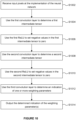
- Figure 12 is a flow chart for a method of determining the weighting parameter(s) using the weighting parameter determination logic 1102.
- the weighting parameter determination logic 1102 comprises gradient determination logic 1104 and weighting parameter calculation logic 1106.
- the gradient determination logic 1104 determines indications of image gradients for the image region based on the input pixels.
- the gradient determination logic 1104 receives and operates on a patch of input pixels. Indications of two image gradients in different directions may be determined.
- the gradient determination logic 1104 applies a first gradient kernel (which may be referred to as a horizontal gradient kernel) to the input pixels to determine an indication of an image gradient in a horizontal direction, dx.
- the gradient determination logic 1104 also applies a second gradient kernel (which may be referred to as a vertical gradient kernel) to the input pixels to determine an indication of an image gradient in a vertical direction, dy.
- the indications of the image gradients in the horizontal and vertical directions (dx and dy) are provided to the weighting parameter calculation logic 1106.
- step S1204 the weighting parameter calculation logic 1106 uses the determined indications of image gradients to determine the one or more weighting parameters.
- the weighting parameter calculation logic 1106 determines and outputs the two weighting parameters a and b .
- the horizontal gradient kernel which is applied to the input pixels may be 0 0 0 0 0 ⁇ 1 ⁇ 1 0 1 1 ⁇ 1 ⁇ 1 0 1 1 ⁇ 1 ⁇ 1 0 1 1 0 0 0 0 0 0 0 , and this may be applied to a 5x5 block of input pixels.
- This horizontal gradient kernel may be represented as ⁇ 1 ⁇ 1 0 1 1 ⁇ 1 ⁇ 1 0 1 1 ⁇ 1 ⁇ 1 0 1 1 because the weights in the top and bottom rows are all zeros.
- "Applying" a kernel to the input pixels means that a weighted sum of the input pixels is performed using the kernel values as weights of the weighted sum. Applying the horizontal gradient kernel to the input pixels and taking the absolute value will output a scalar value, dx, which indicates an image gradient strength in the x direction.
- the horizontal gradient kernel could be defined to be the negative of the kernel given above.
- the vertical gradient kernel which is applied to the input pixels may be 0 ⁇ 1 ⁇ 1 ⁇ 1 0 0 ⁇ 1 ⁇ 1 ⁇ 1 0 0 0 0 0 0 0 0 1 1 1 1 0 , and this may be applied to a 5x5 block of input pixels.
- the vertical gradient kernel may be represented as ⁇ 1 ⁇ 1 ⁇ 1 ⁇ 1 ⁇ 1 ⁇ 1 0 0 0 0 1 1 1 1 1 1 1 because the weights in the leftmost and rightmost columns are all zeros.
- Applying the vertical gradient kernel to the input pixels and taking the absolute value will output a scalar value, dy, which indicates an image gradient strength in the y direction.
- the vertical gradient kernel could be defined to be the negative of the kernel given above.
- the values of dx and dy can be considered to be components of an image gradient vector [dx, dy], with dx and dy being scalar values.
- a line that is perpendicular to the image gradient vector can be considered to represent an edge direction because by definition an image gradient on an edge is perpendicular to the direction of the edge.
- the weighting parameter calculation logic 1106 uses the determined indications of image gradients (e.g. dx and dy) to determine one or more weighting parameters (e.g. " a " and " b ").
- ) + 0.5,0,1), and a second weighting parameter, b , could be determined as b 1 - a , where m is a tuneable parameter.
- weighting parameters can be determined from the determined indications of image gradients (e.g. dx and dy) that satisfy the conditions mentioned above, some of which are given below. Furthermore, in some examples only a single weighting parameter (e.g. a ) is calculated, and the value of the other weighting parameter (e.g. b ) is determined from the calculated weighting parameter, e.g. as (1 - a ) .
- Tuneable parameters may be set, e.g. via registers, to change the behaviour of the processing module as desired.
- the upsampled pixels in the block of upsampled pixels 404 are non-sharpened upsampled pixels, i.e. no sharpening is applied when the upsampling is performed.
- step S602 involves applying a single first kernel to input pixels horizontally adjacent to the upsampled pixel being determined to determine the horizontal component
- step S604 involves applying a single second kernel to input pixels vertically adjacent to the upsampled pixel being determined to determine the vertical component.
- the upsampled pixels in the block of upsampled pixels are sharpened upsampled pixels, i.e. sharpening is applied when the upsampling is performed.
- Figure 13 illustrates pixel determination logic 1300 configured to determine sharpened upsampled pixels.
- the pixel determination logic 1300 may be implemented on a processing module (e.g. processing module 402 shown in Figure 4 ).
- the pixel determination logic 1300 is configured to receive input pixels 1302, process the input pixels and output a block of sharpened upsampled pixels 1310.
- the input pixels 1302 are represented with two input blocks (denoted 1304 1 and 1304 2 in Figure 13 ), which correspond to the input blocks 304 and 306 described above.
- one of the two input blocks e.g.
- input block 1304 1 comprises input pixels having locations corresponding to locations within odd rows of a repeating quincunx arrangement of upsampled pixel locations
- the other of the two input blocks e.g. input block 1304 2
- Representing the input pixels with two input blocks in this way means that the format in which the input pixels are provided to the pixel determination logic 1300 is denser than if the input pixels were received in one block (e.g. as block 302 shown in Figure 3 ).
- Increasing the density of the format in which the input pixels are received is beneficial since it reduces the bandwidth (i.e.
- the pixel determination logic 1300 comprises six pairs of kernels 1306, wherein each pair of kernels 1306 comprises one kernel to be applied to the first input block 1304 1 and another kernel to be applied to the second input block 1304 2 .
- the pixel determination logic 1300 also comprises two blocks of weighted sum logic 1308.
- the logic of the processing module comprising the pixel determination logic 1300 may be implemented in hardware, software, or a combination thereof. A hardware implementation normally provides for a reduced latency and power consumption compared to a software implementation.
- the pixel determination logic 1300 is likely to be used in the same manner a large number of times on each image being upsampled, and since latency is very important in, for example, real-time super resolution applications, it is likely that implementing the pixel determination logic 1300 in hardware (e.g. in fixed function circuitry) will be preferable to implementing the logic in software. However, a software implementation is still possible and may be preferable in some situations.
- Figure 14 is a flow chart for a method of determining a block of sharpened upsampled pixels using the pixel determination logic 1300.
- step S1402 the two input blocks of input pixels 1304 1 and 1304 2 are received at the pixel determination logic 1300.
- the pixel determination logic 1300 determines each of the sharpened upsampled pixels in the block of sharpened upsampled pixels 1310 by performing steps S1404, S1406 and S1408.
- the pixel determination logic 1300 For each sharpened upsampled pixel in the block of sharpened upsampled pixels 1310 the pixel determination logic 1300: (i) in step S1404, applies a first set of one or more kernels to input pixels of the first input block 1304 1 ; (ii) in step S1406, applies a second set of one or more kernels to input pixels of the second input block 1304 2 ; and (iii) in step S1408, combines the results of applying the first set of one or more kernels and applying the second set of one or more kernels to determine the sharpened upsampled pixel.
- Each of the kernels 1306 is configured to perform upsampling and sharpening. In other words, sharpening and upsampling (e.g.
- one of the kernels of the first set (that is applied to input pixels of the first input block 1304 1 ) has a first subset of values of a full sharp upsampling kernel and one of the kernels of the second set (that is applied to input pixels of the second input block 1304 2 ) has a second subset of values of the full sharp upsampling kernel.
- Figure 17 does not show the exact values in the sharpening kernel 1704 or the full sharp upsampling kernel 1706, but it is to be understood that positive values are shown with “+” symbols and negative values are shown with “-” symbols, wherein a value denoted “++++” has a larger magnitude than a value denoted "++", and wherein a value denoted "- -” has a larger magnitude than a value denoted "-”. It will be understood that this notation is indicative of the general shape of linear spatially invariant sharpening kernels, and that variations on this are possible, for example a more "spread out" central maximum.
- the bottom left output pixel of the block of output pixels 2724 is determined by summing: (i) the result of multiplying the bottom left non-sharp upsampled pixel of the block of non-sharp upsampled pixels 2712 by the weight w non-sharp , and (ii) the result of multiplying the bottom left sharp upsampled pixel of the block of sharp upsampled pixels 2718 by the weight w sharp .
- the output pixel determination logic 2722 blends the non-sharp and sharp upsampled pixels using weighted sums.
- the weights of the weighted sums are what makes the sharpening "adaptive" because the weights are dependent upon the values of the input pixels 2702. In particular, the weights are dependent upon a measure of contrast for the input pixels 2702. Performing weighted sums and just altering the weights of the sums to make the sharpening 'adaptive' is very efficient to implement, e.g. in (low cost) hardware, whilst providing surprisingly beneficial effects.
- the adaptive sharpening unit 2700 which performs the adaptive sharpening technique has very low latency, power consumption and/or silicon area compared to conventional adaptive sharpening techniques.
- w non-sharp and w sharp are the same for all pixels in the block of output pixels 804, but it will be appreciated that in other examples they may be different, for example by deriving them from measurements of contrast from different regions of the input pixels 2702. Therefore, in the main examples described herein, there is a single indication of contrast for a block of input pixels, and the weights of the weighted sums for determining the output pixels of the block of output pixels are based on the single indication of contrast; whereas in some other examples, there may be a plurality of indications of contrast for the block of input pixels, wherein for each of the output pixels of the block of output pixels, the weights of the weighted sum for determining that output pixel may be based on a respective one of the plurality of indications of contrast.
- step S2814 the block of output pixels 2724 is output from the output pixel determination logic 2722, and output from the adaptive sharpening unit 2700.
- the output pixels in the block of output pixels 2724 have been upsampled and adaptively sharpened.
- the method can be repeated for the next block of input pixels by striding across the input pixels in the input blocks 2706 and 2708 with a stride of 1, and by striding the output by 2.
- the pixels may be processed in raster scan order, i.e. in rows from top to bottom and within each row from left to right, or in any other suitable order, e.g. boustrophedon order or Morton order.
- the block of output pixels 2724 has been output from the adaptive sharpening unit 2700 it may be used in any suitable manner, e.g. it may be stored in a memory, displayed on a display or transmitted to another device.
- the neural network which can be implemented in the weighting parameter determination logic is trained to output an indication of one or more weighting parameters for use in applying upsampling to input pixels to determine a block of upsampled pixels.
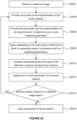
- Figure 29 shows a training module 2900 configured to train a neural network in this way.
- the training module 2900 comprises input logic 2904, upsampling logic 2906, an implementation of the neural network 2908 (which may correspond to the implementation of the neural network 900 described above), update logic 2910 and comparison logic 2912.
- the logic of the training module 2900 may be implemented in hardware (e.g. fixed function circuitry) or software, or any combination thereof.
- the input logic 2904 determines a subset of the pixels of the reference image.
- the subset of the pixels of the reference image may be referred to as a "sparse" subset of the pixels of the reference image because it includes fewer than all of the pixels of the reference image.
- the sparse subset of the pixels are those pixels of the reference image representing an image region and having locations corresponding to a repeating quincunx arrangement (or chequer board pattern) as described above.
- the image region may be a portion of the reference image (e.g. represented by a 1 0x10 block of pixels of the reference image).
- the network may be trained as a convolutional neural network (CNN) on a batch of one or more entire images or crops of images (e.g.
- CNN convolutional neural network
- a 10x10 input window is the receptive field of the network (i.e. the region of the input that contributes to a given output block).
- the pixels in the sparse subset are provided as input pixels to the implementation of the neural network 2908.
- the input pixels may be provided to the implementation of the neural network 2908 in two input blocks, wherein one of the two input blocks comprises the input pixels having locations corresponding to locations within odd rows of the repeating quincunx arrangement of upsampled pixel locations, and the other of the two input blocks comprises the input pixels having locations corresponding to locations within even rows of the repeating quincunx arrangement of upsampled pixel locations.
- the pixels in the sparse subset are also provided to the upsampling logic 2906 in the two input blocks.
- the remaining pixels, i.e. the other half of the pixels of the reference image which are not included in the sparse subset are provided to the comparison logic 2912.
- the input pixels used for training the neural network may not have the same format as described above in relation to the use of the implementation of the neural network. For example, for the purposes of training the neural network, all the pixels from odd rows may be put into one channel and all the pixels from even rows may be put into another channel.
- the input to the neural network during training is (B, H/2, W/2, 2), where B is the batch size, H is the height of the reference image, W is the width of the reference image, and 2 is the number of channels.
- the output data of weighting parameters has a size (B, H/2, W/2, 1).
- entire tensors/images may be used when training (for simplicity), wherein the tensors/images can be broken down into patches during implementation of the neural network to achieve performance and memory benefits.
- step S3006 the implementation of the neural network 2908 processes the input pixels (i.e. the pixels of the reference image in the sparse subset) to determine an indication of one or more weighting parameters indicative of relative horizontal and vertical variation of the input pixels within the image region.
- the implementation of the neural network 2908 may correspond to the implementation of the neural network 900 described above, and step S3006 can be performed as described above with reference to the implementation of the neural network 900 in order to determine the indication of the one or more weighting parameters.
- the relative horizontal and vertical variation of the input pixels within the image region may be indicative of anisotropic image features in the image region, e.g. one or more of edges, texture and high frequency content in the image region.
- the indication of the one or more weighting parameters is provided to the upsampling logic 2906.
- step S3008 the upsampling logic 2906 applies upsampling to the input pixels (i.e. the pixels of the reference image in the sparse subset) to determine a block of upsampled pixels.
- the upsampling logic can perform any of the upsampling methods described herein, which may or may not include sharpening and/or adaptive sharpening.
- step S3008 comprises determining one or more of the upsampled pixels of the block of upsampled pixels in accordance with the relative horizontal and vertical variation of the input pixels within the image region indicated by the one or more weighting parameters. Upsampled pixels determined by the upsampling logic 2906 are provided to the comparison logic 2912.
- step S3010 the comparison logic 2912 compares upsampled pixels of the block of upsampled pixels determined by the upsampling logic 2906, at locations which do not correspond to locations of pixels in the sparse subset of pixels of the reference image, with pixels of the reference image at corresponding locations.
- the pixels of the reference image at these corresponding locations are the "remaining pixels" provided to the comparison logic 2912 by the input logic 2904, and these pixels are considered to be ground truth pixels. Therefore, differences between the upsampled pixels determined by the upsampling logic 2906 and these corresponding ground truth pixels are considered to be due to errors in the upsampling process.
- Step S3010 involves calculating an indication of the errors between the upsampled pixels of the block of upsampled pixels and the pixels of the reference image at the corresponding locations.
- the indication of the errors may be calculated using an L1 loss function (which is based on a sum of absolute differences).
- the neural network can be trained with a view to reducing these errors.
- the indication of these errors is provided to the update logic 2910.
- a person skilled in the art would know how the one or more parameters of the neural network could be trained so that the implementation of the neural network 2908 outputs an indication of the weighting parameter(s) which results in the upsampling logic 2906 determining upsampled pixels that are closer to the corresponding ground truth pixels of the reference image.
- the training may involve using a numerical optimiser based on gradient descent by back-propagation of error.
- the updating of the parameter(s) of the neural network in step S3012 may be by an amount per iteration based on a predetermined learning rate.
- the training of the neural network may use Quantization Aware Training (QAT).
- QAT Quantization Aware Training
- MAC Multiply-Accumulate
- the neural network is defined using coefficients (e.g. the weights), and the trained neural network may be hardcoded in a hardware implementation of the neural network, e.g.
- Each coefficient of the neural network may be determined individually, e.g. individual coefficient bit depths are possible.
- Each of the coefficients may be determined to have a low bit-depth, and the bit depths of the coefficients may be determined individually, e.g. learned/trained individually, thereby allowing for more optimal (i.e. smaller) bit-depths to be used (compared to determining a shared bit depth for an entire layer or channel of the neural network).
- Each of the coefficients may be removed from the network, e.g. by means of training for sparsity.
- a coefficient may be removed from the neural network if a bit depth of the coefficient is learnt to be zero. That is, each of the coefficients may be removed from the neural network if its effect on a quality of the indications of the one or more weighting parameters output from the neural network is determined to be sufficiently small.
- Removing coefficients from the neural network means that the latency, power consumption and/or silicon area of the implementation of the neural network can be reduced. For example, coefficients with a zero value (or with a value that is closer to zero than a threshold) can often be removed from the neural network without having a significant detrimental effect on the quality of the outputs from the neural network.
- sparsity can be implemented in an unstructured, per-coefficient manner, which would ordinarily be hard to exploit. This may allow entire multiplies to be skipped, which results in significant power and area savings.
- the neural network is simple. In particular, since the neural network is used just to determine and output the indication of the weighting parameter(s) (e.g. rather than to determine and output the upsampled pixels) it can be small and implemented with low silicon area, power consumption and latency.
- the neural network may comprise first, second and third convolution layers and first and second ReLUs (as shown in Figure 9 ).
- step S3014 the training module 2900 determines whether another iteration for a different image region (e.g. in the reference image or in a different reference image) is to be performed. If another iteration is to be performed then the method passes back to step S3004 and the next iteration is performed for the next image region. When this next iteration is performed, the implementation of the neural network 2908 implements the neural network with the updated parameter(s) following step S3012. In some cases where the next image region is part of a new batch of one or more reference images then the method may pass back to step S3002 rather than to step S3004 so that the new reference image(s) can be received.
- a different image region e.g. in the reference image or in a different reference image
- step S3014 If it is determined in step S3014 that another iteration is not to be performed for a different image region(e.g. because sufficient training iterations have been performed or because the magnitude of the errors determined in step S3010 are below a threshold) then the method passes from step S3014 to step S3018.
- step S3018 the parameters of the neural network (having been updated by the previous steps of the method shown in Figure 30 ) are stored, e.g. in a memory.
- the parameters of the neural network stored in step S3018 can be retrieved and used to implement the trained neural network.
- the parameters of the neural network may be "baked into” the hardware, so functionality is fixed. This means that the multiplications are by fixed numbers, which makes the hardware considerably more efficient in terms of power and area.
- Figure 31 shows a computer system in which the processing modules described herein may be implemented.
- the computer system comprises a CPU 3102, a GPU 3104, a memory 3106, a neural network accelerator (NNA) 3108 and other devices 3114, such as a display 3116, speakers 3118 and a camera 3122.
- a processing block 3110 (corresponding to the processing modules described herein) is implemented on the GPU 3104. In other examples, one or more of the depicted components may be omitted from the system, and/or the processing block 3110 may be implemented on the CPU 3102 or within the NNA 3108 or in a separate block in the computer system.
- the components of the computer system can communicate with each other via a communications bus 3120.
- processing modules described herein are shown as comprising a number of functional blocks. This is schematic only and is not intended to define a strict division between different logic elements of such entities. Each functional block may be provided in any suitable manner. It is to be understood that intermediate values described herein as being formed by a processing module need not be physically generated by the processing module at any point and may merely represent logical values which conveniently describe the processing performed by the processing module between its input and output.
- the processing modules described herein may be embodied in hardware on an integrated circuit.
- the processing modules described herein may be configured to perform any of the methods described herein.
- any of the functions, methods, techniques or components described above can be implemented in software, firmware, hardware (e.g., fixed logic circuitry), or any combination thereof.
- the terms “module,” “functionality,” “component”, “element”, “unit”, “block” and “logic” may be used herein to generally represent software, firmware, hardware, or any combination thereof.
- the module, functionality, component, element, unit, block or logic represents program code that performs the specified tasks when executed on a processor.
- a computer-readable storage medium examples include a random-access memory (RAM), read-only memory (ROM), an optical disc, flash memory, hard disk memory, and other memory devices that may use magnetic, optical, and other techniques to store instructions or other data and that can be accessed by a machine.
- RAM random-access memory
- ROM read-only memory
- optical disc optical disc
- flash memory hard disk memory
- hard disk memory and other memory devices that may use magnetic, optical, and other techniques to store instructions or other data and that can be accessed by a machine.
- Computer program code and computer readable instructions refer to any kind of executable code for processors, including code expressed in a machine language, an interpreted language or a scripting language.
- Executable code includes binary code, machine code, bytecode, code defining an integrated circuit (such as a hardware description language or netlist), and code expressed in a programming language code such as C, Java or OpenCL.
- Executable code may be, for example, any kind of software, firmware, script, module or library which, when suitably executed, processed, interpreted, compiled, executed at a virtual machine or other software environment, cause a processor of the computer system at which the executable code is supported to perform the tasks specified by the code.
- An integrated circuit definition dataset may be in the form of computer code, for example as a netlist, code for configuring a programmable chip, as a hardware description language defining hardware suitable for manufacture in an integrated circuit at any level, including as register transfer level (RTL) code, as high-level circuit representations such as Verilog or VHDL, and as low-level circuit representations such as OASIS (RTM) and GDSII.
- RTL register transfer level
- RTM high-level circuit representations
- GDSII GDSI
- the layout processing system 3204 is configured to receive and process the IC definition dataset to determine a circuit layout.
- Methods of determining a circuit layout from an IC definition dataset are known in the art, and for example may involve synthesising RTL code to determine a gate level representation of a circuit to be generated, e.g. in terms of logical components (e.g. NAND, NOR, AND, OR, MUX and FLIP-FLOP components).
- a circuit layout can be determined from the gate level representation of the circuit by determining positional information for the logical components. This may be done automatically or with user involvement in order to optimise the circuit layout.
- the layout processing system 3204 may output a circuit layout definition to the IC generation system 3206.
- a circuit layout definition may be, for example, a circuit layout description.
- the IC generation system 3206 generates an IC according to the circuit layout definition, as is known in the art.
- the IC generation system 3206 may implement a semiconductor device fabrication process to generate the IC, which may involve a multiple-step sequence of photo lithographic and chemical processing steps during which electronic circuits are gradually created on a wafer made of semiconducting material.
- the circuit layout definition may be in the form of a mask which can be used in a lithographic process for generating an IC according to the circuit definition.
- the circuit layout definition provided to the IC generation system 3206 may be in the form of computer-readable code which the IC generation system 3206 can use to form a suitable mask for use in generating an IC.
- processing of the integrated circuit definition dataset at an integrated circuit manufacturing system may configure the system to manufacture a processing module without the IC definition dataset being processed so as to determine a circuit layout.
- an integrated circuit definition dataset may define the configuration of a reconfigurable processor, such as an FPGA, and the processing of that dataset may configure an IC manufacturing system to generate a reconfigurable processor having that defined configuration (e.g. by loading configuration data to the FPGA).
- an integrated circuit definition dataset could include software which runs on hardware defined at the dataset or in combination with hardware defined at the dataset.
- the IC generation system may further be configured by an integrated circuit definition dataset to, on manufacturing an integrated circuit, load firmware onto that integrated circuit in accordance with program code defined at the integrated circuit definition dataset or otherwise provide program code with the integrated circuit for use with the integrated circuit.
- performance improvements may include one or more of increased computational performance, reduced latency, increased throughput, and/or reduced power consumption.
- performance improvements can be traded-off against the physical implementation, thereby improving the method of manufacture. For example, a performance improvement may be traded against layout area, thereby matching the performance of a known implementation but using less silicon. This may be done, for example, by reusing functional blocks in a serialised fashion or sharing functional blocks between elements of the devices, apparatus, modules and/or systems.
Landscapes
- Engineering & Computer Science (AREA)
- Physics & Mathematics (AREA)
- General Physics & Mathematics (AREA)
- Theoretical Computer Science (AREA)
- Artificial Intelligence (AREA)
- Evolutionary Computation (AREA)
- Multimedia (AREA)
- Signal Processing (AREA)
- Image Processing (AREA)
- Apparatus For Radiation Diagnosis (AREA)
Applications Claiming Priority (1)
| Application Number | Priority Date | Filing Date | Title |
|---|---|---|---|
| GB2319651.2A GB2636743A (en) | 2023-12-20 | 2023-12-20 | Upsampling |
Publications (2)
| Publication Number | Publication Date |
|---|---|
| EP4575973A2 true EP4575973A2 (de) | 2025-06-25 |
| EP4575973A3 EP4575973A3 (de) | 2025-07-09 |
Family
ID=89662541
Family Applications (2)
| Application Number | Title | Priority Date | Filing Date |
|---|---|---|---|
| EP24220664.7A Pending EP4575973A3 (de) | 2023-12-20 | 2024-12-17 | Upsampling |
| EP24220674.6A Pending EP4575974A1 (de) | 2023-12-20 | 2024-12-17 | Upsampling |
Family Applications After (1)
| Application Number | Title | Priority Date | Filing Date |
|---|---|---|---|
| EP24220674.6A Pending EP4575974A1 (de) | 2023-12-20 | 2024-12-17 | Upsampling |
Country Status (4)
| Country | Link |
|---|---|
| US (1) | US20250322491A1 (de) |
| EP (2) | EP4575973A3 (de) |
| CN (1) | CN120182090A (de) |
| GB (1) | GB2636743A (de) |
Family Cites Families (2)
| Publication number | Priority date | Publication date | Assignee | Title |
|---|---|---|---|---|
| WO2012012444A2 (en) * | 2010-07-19 | 2012-01-26 | Dolby Laboratories Licensing Corporation | Enhancement methods for sampled and multiplexed image and video data |
| GB2617220B (en) * | 2022-09-30 | 2025-02-05 | Imagination Tech Ltd | Upsampling blocks of pixels |
-
2023
- 2023-12-20 GB GB2319651.2A patent/GB2636743A/en active Pending
-
2024
- 2024-12-17 EP EP24220664.7A patent/EP4575973A3/de active Pending
- 2024-12-17 EP EP24220674.6A patent/EP4575974A1/de active Pending
- 2024-12-18 CN CN202411870406.5A patent/CN120182090A/zh active Pending
- 2024-12-20 US US18/990,463 patent/US20250322491A1/en active Pending
Also Published As
| Publication number | Publication date |
|---|---|
| EP4575973A3 (de) | 2025-07-09 |
| CN120182090A (zh) | 2025-06-20 |
| EP4575974A1 (de) | 2025-06-25 |
| US20250322491A1 (en) | 2025-10-16 |
| GB202319651D0 (en) | 2024-01-31 |
| GB2636743A (en) | 2025-07-02 |
Similar Documents
| Publication | Publication Date | Title |
|---|---|---|
| Lai et al. | Deep laplacian pyramid networks for fast and accurate super-resolution | |
| Zhao et al. | GUN: Gradual upsampling network for single image super-resolution | |
| US8457429B2 (en) | Method and system for enhancing image signals and other signals to increase perception of depth | |
| US8417050B2 (en) | Multi-scale robust sharpening and contrast enhancement | |
| CN115908156B (zh) | 渲染3d场景的图像的方法、图形处理单元和存储介质 | |
| US8731318B2 (en) | Unified spatial image processing | |
| CN117830145A (zh) | 像素块的自适应锐化 | |
| He et al. | FPGA-based real-time super-resolution system for ultra high definition videos | |
| CN108765282A (zh) | 基于fpga的实时超分辨方法及系统 | |
| CN117830146A (zh) | 像素块的自适应锐化 | |
| EP4575973A2 (de) | Upsampling | |
| EP4345734A1 (de) | Adaptive schärfung für blöcke von hochabgetasteten pixeln | |
| GB2623071A (en) | Adaptive sharpening for blocks of pixels | |
| US20250322490A1 (en) | Weighting parameters for use in applying upsampling | |
| Gabiger et al. | A synchronous FPGA design of a bilateral filter for image processing | |
| EP4345739A1 (de) | Adaptive schärfung für pixelblöcke | |
| CN117217987A (zh) | 图像处理方法、装置、设备及系统 | |
| US20260051024A1 (en) | Upsampling Input Pixels of a Frame Using a Jitter Pattern over a Sequence of Frames | |
| EP4575977A1 (de) | Upsampling | |
| JP7544359B2 (ja) | 最適化装置、訓練装置、合成装置、それらの方法、およびプログラム | |
| Kang et al. | DCID: A divide and conquer approach to solving the trade-off problem between artifacts caused by enhancement procedure in image downscaling | |
| Shen | Single Image Super-Resolution via Deep Dense Network | |
| Hu et al. | Dual-Stem Transformer for Efficient Image Denoising with Spatial-Channel Attention |
Legal Events
| Date | Code | Title | Description |
|---|---|---|---|
| PUAI | Public reference made under article 153(3) epc to a published international application that has entered the european phase |
Free format text: ORIGINAL CODE: 0009012 |
|
| STAA | Information on the status of an ep patent application or granted ep patent |
Free format text: STATUS: THE APPLICATION HAS BEEN PUBLISHED |
|
| PUAL | Search report despatched |
Free format text: ORIGINAL CODE: 0009013 |
|
| AK | Designated contracting states |
Kind code of ref document: A2 Designated state(s): AL AT BE BG CH CY CZ DE DK EE ES FI FR GB GR HR HU IE IS IT LI LT LU LV MC ME MK MT NL NO PL PT RO RS SE SI SK SM TR |
|
| AK | Designated contracting states |
Kind code of ref document: A3 Designated state(s): AL AT BE BG CH CY CZ DE DK EE ES FI FR GB GR HR HU IE IS IT LI LT LU LV MC ME MK MT NL NO PL PT RO RS SE SI SK SM TR |
|
| RIC1 | Information provided on ipc code assigned before grant |
Ipc: H04N 19/80 20140101ALI20250530BHEP Ipc: H04N 19/176 20140101ALI20250530BHEP Ipc: H04N 19/117 20140101ALI20250530BHEP Ipc: H04N 19/59 20140101ALI20250530BHEP Ipc: G06T 3/4046 20240101ALI20250530BHEP Ipc: G06T 3/4053 20240101ALI20250530BHEP Ipc: G06T 3/4007 20240101AFI20250530BHEP |
|
| P01 | Opt-out of the competence of the unified patent court (upc) registered |
Free format text: CASE NUMBER: APP_31932/2025 Effective date: 20250702 |
|
| STAA | Information on the status of an ep patent application or granted ep patent |
Free format text: STATUS: REQUEST FOR EXAMINATION WAS MADE |
|
| 17P | Request for examination filed |
Effective date: 20260105 |