EP4575974A1 - Upsampling - Google Patents
Upsampling Download PDFInfo
- Publication number
- EP4575974A1 EP4575974A1 EP24220674.6A EP24220674A EP4575974A1 EP 4575974 A1 EP4575974 A1 EP 4575974A1 EP 24220674 A EP24220674 A EP 24220674A EP 4575974 A1 EP4575974 A1 EP 4575974A1
- Authority
- EP
- European Patent Office
- Prior art keywords
- pixels
- input
- upsampled
- kernel
- input pixels
- Prior art date
- Legal status (The legal status is an assumption and is not a legal conclusion. Google has not performed a legal analysis and makes no representation as to the accuracy of the status listed.)
- Pending
Links
Images











Classifications
-
- H—ELECTRICITY
- H04—ELECTRIC COMMUNICATION TECHNIQUE
- H04N—PICTORIAL COMMUNICATION, e.g. TELEVISION
- H04N19/00—Methods or arrangements for coding, decoding, compressing or decompressing digital video signals
- H04N19/50—Methods or arrangements for coding, decoding, compressing or decompressing digital video signals using predictive coding
- H04N19/59—Methods or arrangements for coding, decoding, compressing or decompressing digital video signals using predictive coding involving spatial sub-sampling or interpolation, e.g. alteration of picture size or resolution
-
- G—PHYSICS
- G06—COMPUTING OR CALCULATING; COUNTING
- G06T—IMAGE DATA PROCESSING OR GENERATION, IN GENERAL
- G06T3/00—Geometric image transformations in the plane of the image
- G06T3/40—Scaling of whole images or parts thereof, e.g. expanding or contracting
- G06T3/4053—Scaling of whole images or parts thereof, e.g. expanding or contracting based on super-resolution, i.e. the output image resolution being higher than the sensor resolution
-
- G—PHYSICS
- G06—COMPUTING OR CALCULATING; COUNTING
- G06T—IMAGE DATA PROCESSING OR GENERATION, IN GENERAL
- G06T1/00—General purpose image data processing
- G06T1/20—Processor architectures; Processor configuration, e.g. pipelining
-
- G—PHYSICS
- G06—COMPUTING OR CALCULATING; COUNTING
- G06T—IMAGE DATA PROCESSING OR GENERATION, IN GENERAL
- G06T3/00—Geometric image transformations in the plane of the image
- G06T3/40—Scaling of whole images or parts thereof, e.g. expanding or contracting
- G06T3/4007—Scaling of whole images or parts thereof, e.g. expanding or contracting based on interpolation, e.g. bilinear interpolation
-
- G—PHYSICS
- G06—COMPUTING OR CALCULATING; COUNTING
- G06T—IMAGE DATA PROCESSING OR GENERATION, IN GENERAL
- G06T3/00—Geometric image transformations in the plane of the image
- G06T3/40—Scaling of whole images or parts thereof, e.g. expanding or contracting
- G06T3/4046—Scaling of whole images or parts thereof, e.g. expanding or contracting using neural networks
-
- G—PHYSICS
- G06—COMPUTING OR CALCULATING; COUNTING
- G06T—IMAGE DATA PROCESSING OR GENERATION, IN GENERAL
- G06T5/00—Image enhancement or restoration
- G06T5/10—Image enhancement or restoration using non-spatial domain filtering
-
- G—PHYSICS
- G06—COMPUTING OR CALCULATING; COUNTING
- G06T—IMAGE DATA PROCESSING OR GENERATION, IN GENERAL
- G06T5/00—Image enhancement or restoration
- G06T5/60—Image enhancement or restoration using machine learning, e.g. neural networks
-
- G—PHYSICS
- G06—COMPUTING OR CALCULATING; COUNTING
- G06T—IMAGE DATA PROCESSING OR GENERATION, IN GENERAL
- G06T5/00—Image enhancement or restoration
- G06T5/73—Deblurring; Sharpening
-
- H—ELECTRICITY
- H04—ELECTRIC COMMUNICATION TECHNIQUE
- H04N—PICTORIAL COMMUNICATION, e.g. TELEVISION
- H04N19/00—Methods or arrangements for coding, decoding, compressing or decompressing digital video signals
- H04N19/10—Methods or arrangements for coding, decoding, compressing or decompressing digital video signals using adaptive coding
- H04N19/102—Methods or arrangements for coding, decoding, compressing or decompressing digital video signals using adaptive coding characterised by the element, parameter or selection affected or controlled by the adaptive coding
- H04N19/117—Filters, e.g. for pre-processing or post-processing
-
- H—ELECTRICITY
- H04—ELECTRIC COMMUNICATION TECHNIQUE
- H04N—PICTORIAL COMMUNICATION, e.g. TELEVISION
- H04N19/00—Methods or arrangements for coding, decoding, compressing or decompressing digital video signals
- H04N19/10—Methods or arrangements for coding, decoding, compressing or decompressing digital video signals using adaptive coding
- H04N19/169—Methods or arrangements for coding, decoding, compressing or decompressing digital video signals using adaptive coding characterised by the coding unit, i.e. the structural portion or semantic portion of the video signal being the object or the subject of the adaptive coding
- H04N19/17—Methods or arrangements for coding, decoding, compressing or decompressing digital video signals using adaptive coding characterised by the coding unit, i.e. the structural portion or semantic portion of the video signal being the object or the subject of the adaptive coding the unit being an image region, e.g. an object
- H04N19/176—Methods or arrangements for coding, decoding, compressing or decompressing digital video signals using adaptive coding characterised by the coding unit, i.e. the structural portion or semantic portion of the video signal being the object or the subject of the adaptive coding the unit being an image region, e.g. an object the region being a block, e.g. a macroblock
-
- H—ELECTRICITY
- H04—ELECTRIC COMMUNICATION TECHNIQUE
- H04N—PICTORIAL COMMUNICATION, e.g. TELEVISION
- H04N19/00—Methods or arrangements for coding, decoding, compressing or decompressing digital video signals
- H04N19/80—Details of filtering operations specially adapted for video compression, e.g. for pixel interpolation
-
- G—PHYSICS
- G06—COMPUTING OR CALCULATING; COUNTING
- G06T—IMAGE DATA PROCESSING OR GENERATION, IN GENERAL
- G06T2207/00—Indexing scheme for image analysis or image enhancement
- G06T2207/20—Special algorithmic details
- G06T2207/20084—Artificial neural networks [ANN]
Definitions
- upsampling can be applied to input pixels representing an image region to determine a block of upsampled pixels, e.g. for super resolution techniques.
- the term 'super resolution' refers to techniques of upsampling an image that enhance the apparent visual quality of the image, e.g. by estimating the appearance of a higher resolution version of the image.
- super resolution is a challenging problem because, for every patch in a lower-resolution input image, there is a very large number of potential higher-resolution patches that could correspond to it. In other words, super resolution techniques are trying to solve an ill-posed problem, since although solutions exist, they are not unique.
- An image generation process may be an image capturing process, e.g. using a camera.
- an image generation process may be an image rendering process in which a computer, e.g. a graphics processing unit (GPU), renders an image of a virtual scene.
- a computer e.g. a graphics processing unit (GPU)
- GPUs may implement any suitable rendering technique, such as rasterization or ray tracing.
- a GPU can render a 960x540 image (i.e. an image with 518,400 pixels arranged into 960 columns and 540 rows) which can then be upsampled by a factor of 2 in both horizontal and vertical dimensions (which is referred to as ⁇ 2x upsampling') to produce a 1920x1080 image (i.e.
- the GPU renders an image with a quarter of the number of pixels. This results in very significant savings (e.g. in terms of latency, power consumption and/or silicon area of the GPU) during rendering and can for example allow a relatively low-performance GPU to render high-quality, high-resolution images within a low power and area budget, provided a suitably efficient and high-quality super-resolution implementation is used to perform the upsampling. In other examples, different upsampling factors (other than 2x) may be applied.
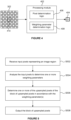
- FIG. 1 illustrates an upsampling process.
- An input image 102 which has a relatively low resolution, is processed by a processing module 104 to produce an output image 106 which has a relatively high resolution.
- the processing module 104 may be implemented as a neural network to upsample the input image 102 to produce the upsampled output image 106.
- Implementing the processing module 104 as a neural network may produce good quality output images, but often requires a high performance computing system (e.g. with large, powerful processing units and memories) to implement the neural network.
- implementing the processing module 104 as a neural network for performing upsampling of images may be unsuitable for reasons of processing time, latency, bandwidth, power consumption, memory usage, silicon area and compute costs. These considerations of efficiency are particularly important in some devices, e.g. small, battery operated devices with limited compute and bandwidth resources, such as mobile phones and tablets.
- Some systems do not use a neural network for performing super resolution on images, and instead use more conventional processing modules. For example, some systems split the problem into two stages: (i) upsampling and (ii) adaptive sharpening.
- the upsampling stage can be performed cheaply, e.g. using bilinear upsampling, and the adaptive sharpening stage can be used to sharpen the image, i.e. reduce the blurring introduced by the upsampling.
- Bilinear upsampling is known in the art and uses linear interpolation of adjacent input pixels in two dimensions to produce output pixels at positions between input pixels.
- a method of applying upsampling to input pixels representing an image region to determine a block of upsampled pixels, wherein the input pixels have locations corresponding to a repeating quincunx arrangement of upsampled pixel locations comprising:
- the one or more weighting parameters may be indicative of relative horizontal and vertical variation of the input pixels within the image region.
- the one or more of the upsampled pixels of the block of upsampled pixels may be determined in accordance with the relative horizontal and vertical variation of the input pixels within the image region indicated by the determined one or more weighting parameters.
- Each of said one or more of the upsampled pixels may be at a respective upsampled pixel location which does not correspond with the location of any of the input pixels.
- the input pixels may be represented in two input blocks.
- One of the two input blocks may comprise the input pixels having locations corresponding to locations within odd rows of the repeating quincunx arrangement of upsampled pixel locations, and the other of the two input blocks may comprise the input pixels having locations corresponding to locations within even rows of the repeating quincunx arrangement of upsampled pixel locations.
- the image region may be part of a current frame within a sequence of frames.
- the input pixels of a first of the input blocks may be rendered for the current frame.
- the input pixels of a second of the input blocks may be determined by performing temporal resampling on pixels of a previous frame using motion vectors.
- Pixels for the previous frame corresponding to the pixel locations of the input pixels of the second input block may have been rendered for the previous frame.
- All of the input pixels may be rendered for the image region.
- Determining each of said one or more of the upsampled pixels may comprise, in accordance with the determined one or more weighting parameters:
- Said combining the determined horizontal and vertical components may comprise:
- Said analysing the input pixels to determine one or more weighting parameters may comprise processing the input pixels with an implementation of a neural network.
- the neural network may have been trained to output an indication of the one or more weighting parameters to be indicative of the directionality of filtering to be applied when upsampling is applied to the input pixels within the image region.
- the neural network may comprise:
- Said analysing the input pixels to determine one or more weighting parameters may comprise:
- Said determining indications of image gradients for the image region may comprise:
- Said using the determined indications of image gradients to determine the one or more weighting parameters may comprise:
- the upsampled pixels in the block of upsampled pixels may be non-sharpened upsampled pixels.
- Said applying one or more first kernels to at least a first subset of the input pixels may comprise applying a single first kernel to input pixels horizontally adjacent to the upsampled pixel being determined.
- Said applying one or more second kernels to at least a second subset of the input pixels may comprise applying a single second kernel to input pixels vertically adjacent to the upsampled pixel being determined.
- the input pixels having locations corresponding to the repeating quincunx arrangement of upsampled pixel locations may be used as the upsampled pixels at those upsampled pixel locations of the block of upsampled pixels.
- the upsampled pixels in the block of upsampled pixels may be sharpened upsampled pixels.
- Said applying one or more first kernels to at least a first subset of the input pixels may comprise applying a first horizontal kernel to input pixels of a first of the image blocks, applying a second horizontal kernel to input pixels of a second of the image blocks, and summing the results of applying the first and second horizontal kernels to determine the horizontal component.
- Said applying one or more second kernels to at least a second subset of the input pixels may comprise applying a first vertical kernel to input pixels of the first of the image blocks, applying a second vertical kernel to input pixels of the second of the image blocks, and summing the results of applying the first and second vertical kernels to determine the vertical component.
- the method may further comprise determining upsampled pixels at locations corresponding to the repeating quincunx arrangement of upsampled pixel locations within the block of upsampled pixels by:
- a processing module configured to apply upsampling to input pixels representing an image region to determine a block of upsampled pixels, wherein the input pixels have locations corresponding to a repeating quincunx arrangement of upsampled pixel locations, the processing module comprising:
- the weighting parameter determination logic may comprise an implementation of a neural network configured to process the input pixels, wherein the neural network has been trained to output the one or more weighting parameters to be indicative of the directionality of filtering to be applied when upsampling is applied to the input pixels within the image region.
- the neural network may comprise:
- processing module configured to perform any of the methods described herein.
- an adaptive sharpening unit configured to apply adaptive sharpening to input pixels representing an image region to determine a block of output pixels, the adaptive sharpening unit comprising:
- processing modules and/or the adaptive sharpening units described herein may be embodied in hardware on an integrated circuit.
- an integrated circuit definition dataset that, when processed in an integrated circuit manufacturing system, configures the integrated circuit manufacturing system to manufacture a processing module or an adaptive sharpening unit as described herein.
- said interpolation kernel may be a bilinear interpolation kernel.
- Said bilinear interpolation kernel may be represented as 0 0.25 0 0.25 1 0.25 0 0.25 0 .
- Said combining the determined horizontal and vertical components may comprise:
- the method may further comprise analysing the input pixels of the first and second input blocks to determine the first and second weighting parameters, wherein the first and second weighting parameters may be indicative of a directionality of filtering to be applied when upsampling is applied to the input pixels.
- the first and second weighting parameters may be indicative of relative horizontal and vertical variation of the input pixels.
- Said analysing the input pixels of the first and second input blocks to determine the first and second weighting parameters may comprise processing the input pixels with an implementation of a neural network.
- the neural network may have been trained to output an indication of the weighting parameters to be indicative of the directionality of filtering to be applied when upsampling is applied to the input pixels.
- the neural network may comprise:
- the first horizontal kernel may have a first subset of values of a full horizontal sharp upsampling kernel and the second horizontal kernel may have a second subset of values of the full horizontal sharp upsampling kernel.
- the full horizontal sharp upsampling kernel may have values which correspond to the upsampled pixel locations and which represent a result of convolving a linear horizontal interpolation kernel with the sharpening kernel.
- the first vertical kernel may have a first subset of values of a full vertical sharp upsampling kernel and the second vertical kernel may have a second subset of values of the full vertical sharp upsampling kernel, wherein the full vertical sharp upsampling kernel may have values which correspond to the upsampled pixel locations and which represent a result of convolving a linear vertical interpolation kernel with the sharpening kernel.
- the first subset of values of the full horizontal sharp upsampling kernel may include the values of the full horizontal sharp upsampling kernel at locations corresponding to the locations of the input pixels in the first of the input blocks.
- the second subset of values of the full horizontal sharp upsampling kernel may include the values of the full horizontal sharp upsampling kernel at locations corresponding to the locations of the input pixels in the second of the input blocks.
- the first subset of values of the full vertical sharp upsampling kernel may include the values of the full vertical sharp upsampling kernel at locations corresponding to the locations of the input pixels in the first of the input blocks
- the second subset of values of the full vertical sharp upsampling kernel may include the values of the full vertical sharp upsampling kernel at locations corresponding to the locations of the input pixels in the second of the input blocks.
- Said linear horizontal interpolation kernel may be represented as [0.5 1 0.5], and said linear vertical interpolation kernel may be represented as 0.5 1 0.5 .
- the sharpening kernel may be an unsharp mask kernel.
- the sharpening kernel may be a truncated sinc kernel.
- the input pixels of the first of the input blocks may be rendered for a current frame within a sequence of frames.
- the input pixels of the second of the input blocks may be determined by performing temporal resampling on pixels of a previous frame using motion vectors.
- Pixels for the previous frame corresponding to the pixel locations of the input pixels of the second input block may have been rendered for the previous frame.
- All of the input pixels of the first and second input blocks may be rendered for a current frame within a sequence of frames.
- a method of applying adaptive sharpening to input pixels representing an image region to determine a block of output pixels, wherein the input pixels are represented in two input blocks comprising:
- a processing module comprising pixel determination logic configured to determine a block of sharpened upsampled pixels, the pixel determination logic being configured to:
- the processing module may further comprise weighting parameter determination logic configured to analyse the input pixels of the first and second input blocks to determine the first and second weighting parameters.
- the first and second weighting parameters may be indicative of a directionality of filtering to be applied when upsampling is applied to the input pixels.
- the weighting parameter determination logic may comprise an implementation of a neural network configured to process the input pixels.
- the neural network may have been trained to output an indication of the weighting parameters to be indicative of the directionality of filtering to be applied when upsampling is applied to the input pixels.
- the neural network may comprise:
- an adaptive sharpening unit configured to apply adaptive sharpening to input pixels representing an image region to determine a block of output pixels, wherein the input pixels are represented in two input blocks, the adaptive sharpening unit comprising:
- the one or more weighting parameters may be indicative of relative horizontal and vertical variation of the input pixels within the image region.
- the input pixels may be represented in two input blocks, wherein one of the two input blocks may comprise the input pixels having locations corresponding to locations within odd rows of the repeating quincunx arrangement of upsampled pixel locations, and the other of the two input blocks may comprise the input pixels having locations corresponding to locations within even rows of the repeating quincunx arrangement of upsampled pixel locations.
- the neural network may have been trained using Quantization Aware Training (QAT).
- QAT Quantization Aware Training
- the neural network may be hardcoded in hardware of the implementation of the neural network.
- Each coefficient of the neural network may have been determined individually.
- the determining of each of the coefficients may comprise one or both of: (i) learning an individual bit depth of the coefficient, and (ii) removing the coefficient from the neural network if a bit depth of the coefficient is learnt to be zero.
- the method may further comprise applying upsampling to the input pixels representing the image region.
- Said upsampling may comprise determining one or more of the upsampled pixels of the block of upsampled pixels in accordance with the directionality of filtering indicated by the one or more weighting parameters.
- Each of said one or more of the upsampled pixels may be at a respective upsampled pixel location which does not correspond with the location of any of the input pixels.
- Determining each of said one or more of the upsampled pixels may comprise, in accordance with the determined one or more weighting parameters:
- Said combining the determined horizontal and vertical components may comprise:
- the upsampled pixels in the block of upsampled pixels may be non-sharpened upsampled pixels.
- the upsampled pixels in the block of upsampled pixels may be sharpened upsampled pixels.
- a processing module configured to determine an indication of one or more weighting parameters for use in applying upsampling to input pixels representing an image region to determine a block of upsampled pixels
- the processing module comprising: an implementation of a neural network, wherein the neural network has been trained to output an indication of the one or more weighting parameters to be indicative of a directionality of filtering to be applied when upsampling is applied to the input pixels within the image region, wherein the implementation of the neural network is configured to:
- the neural network may comprise: a first convolution layer configured to determine a first intermediate tensor based on the input pixels, wherein the first intermediate tensor extends in only one of a horizontal dimension and a vertical dimension with respect to the dimensions of the image region represented by the input pixels.
- the image region may be part of an input image. It may be the case that the upsampling is to be performed iteratively for a plurality of partially overlapping image regions within the input image.
- the neural network may further comprise a buffer configured to store the first intermediate tensor. It may be the case that the first convolution layer is configured to operate on input pixels within a first portion of a current image region that does not overlap with a previous image region, but to not operate on input pixels within a second portion of the current image region that does overlap with the previous image region, to determine the first intermediate tensor.
- the neural network may further comprise:
- the neural network may further comprise a first rectified linear unit implemented between the first convolution layer and the second convolution layer, and a second rectified linear unit implemented between the second convolution layer and the third convolution layer.
- the first rectified linear unit may be configured to set negative values in the first intermediate tensor to zero.
- the second rectified linear unit may be configured to set negative values in the second intermediate tensor to zero.
- the implementation of the neural network may not comprise any linestores.
- the neural network may have been trained using Quantization Aware Training (QAT).
- QAT Quantization Aware Training
- the processing module may further comprise pixel determination logic configured to determine one or more of the upsampled pixels of the block of upsampled pixels in accordance with the directionality of filtering indicated by the determined one or more weighting parameters.
- a method of training a neural network to output an indication of one or more weighting parameters for use in applying upsampling to input pixels to determine a block of upsampled pixels comprising: receiving a reference image having pixels at upsampled pixel locations; and iteratively:
- the one or more weighting parameters may be indicative of relative horizontal and vertical variation of the input pixels within the image region.
- the one or more of the upsampled pixels of the block of upsampled pixels may be determined in accordance with the relative horizontal and vertical variation of the input pixels within the image region indicated by the determined one or more weighting parameters.
- the input pixels may have locations corresponding to a repeating quincunx arrangement of upsampled pixel locations.
- Said providing input pixels to an implementation of the neural network may comprise providing two input blocks to the implementation of the neural network, wherein one of the two input blocks may comprise the input pixels having locations corresponding to locations within odd rows of the repeating quincunx arrangement of upsampled pixel locations, and the other of the two input blocks may comprise the input pixels having locations corresponding to locations within even rows of the repeating quincunx arrangement of upsampled pixel locations.
- Said comparing may comprise calculating an indication of errors between the upsampled pixels of the block of upsampled pixels, at locations which do not correspond to locations of pixels in the subset of pixels of the reference image, and the pixels of the reference image at the corresponding locations, wherein in a current iteration said updating may comprise updating the one or more parameters of the neural network based on the calculated indication of the errors.
- the indication of the errors may be calculated using an L1 loss function.
- Said updating may comprise updating the one or more parameters of the neural network by an amount per iteration based on a predetermined learning rate.
- the neural network may further comprise a second convolution layer and a third convolution layer. Said processing the input pixels with the implementation of the neural network may further comprise:
- Said updating one or more parameters of the neural network may comprise updating a parameter of one or more of the first, second and third convolution layers.
- the neural network may further comprise a first rectified linear unit implemented between the first convolution layer and the second convolution layer, and a second rectified linear unit implemented between the second convolution layer and the third convolution layer.
- Said processing the input pixels with the implementation of the neural network may further comprise:
- the neural network may be trained using Quantization Aware Training (QAT).
- QAT Quantization Aware Training
- Each coefficient of the neural network may be determined individually.
- the determining of each of the coefficients may comprise one or both of: (i) learning an individual bit depth of the coefficient, and (ii) removing the coefficient from the neural network if a bit depth of the coefficient is learnt to be zero.
- the trained neural network may be hardcoded in a hardware implementation of the neural network.
- the hardware implementation of the neural network may be configured to process input pixels representing an image region and output an indication of one or more weighting parameters for use in applying upsampling to the input pixels to determine a block of upsampled pixels.
- Determining each of said one or more of the upsampled pixels may comprise, in accordance with the determined one or more weighting parameters:
- Said comparison logic may be configured to calculate an indication of errors between the upsampled pixels of the block of upsampled pixels, at locations which do not correspond to locations of pixels in the subset of pixels of the reference image, and the pixels of the reference image at the corresponding locations.
- Said updating logic may be configured to, in a current iteration, update the one or more parameters of the neural network based on the calculated indication of the errors.
- the neural network may further comprise:
- the training module may be configured to train the neural network using Quantization Aware Training (QAT).
- QAT Quantization Aware Training
- training module configured to perform the training methods described herein.
- the training module may be embodied in hardware on an integrated circuit.
- an integrated circuit definition dataset that, when processed in an integrated circuit manufacturing system, configures the integrated circuit manufacturing system to manufacture a training module as described herein.
- an integrated circuit manufacturing system comprising: a non-transitory computer readable storage medium having stored thereon a computer readable description of the processing module; a layout processing system configured to process the computer readable description so as to generate a circuit layout description of an integrated circuit embodying the processing module; and an integrated circuit generation system configured to manufacture the processing module according to the circuit layout description.
- Figure 2 shows input pixels 202 having locations corresponding to a repeating quincunx arrangement of upsampled pixel locations.
- half of the upsampled (output) pixel locations e.g. location 204 are shown with hatching in Figure 2 and correspond to the location of an input pixel; whereas the other half of the upsampled pixel locations (e.g. location 206) are shown without hatching in Figure 2 and do not correspond to the location of an input pixel.
- the repeating quincunx arrangement can be considered to be a 'chequer board' pattern.
- the input pixels 202 are processed, as described herein, to determine a block of upsampled pixels which includes an upsampled pixel at some of the upsampled pixel locations shown in Figure 2 which do not correspond to the location of an input pixel.
- the density of upsampled pixels is double the density of input pixels.
- the use of the repeating quincunx arrangement means that output pixel locations that do not correspond to the location of an input pixel (shown without hatching in Figure 2 ) are horizontally adjacent to two output pixel locations that do correspond to the location of an input pixel (shown with hatching in Figure 2 ) and are vertically adjacent to two output pixel locations that do correspond to the location of an input pixel (shown with hatching in Figure 2 ).
- At least one weighting parameter is determined which is indicative of the weights used in the weighted sums for determining the upsampled pixels.
- the weighting parameter(s) are determined using an implementation of a neural network.
- the neural network has been trained to output an indication of the weighting parameter(s) to be indicative of a directionality of filtering to be applied when upsampling is applied to the input pixels.
- the one or more weighting parameters may be indicative of the relative horizontal and vertical variation of the input pixels within the image region.
- the indication of the weighting parameter(s) could be the weighting parameter(s).
- the indication of the weighting parameter(s) could be something other than the weighting parameter(s) from which the weighting parameter(s) can be determined.
- the indication of the weighting parameters may be some but not all of the weighting parameters, wherein the other weighting parameter(s) can be derived from the weighting parameter(s) that are explicitly included in the indication.
- Using a neural network to determine the weighting parameter(s) allows the determination of the weighting parameter(s) to adapt to give perceptually good results without needing to design an algorithm to explicitly exploit directional cues in the image region, be they edges, textures, high frequency content or otherwise. This is advantageous because hand-engineering a system to exploit some or all of these directional cues is difficult and time consuming, and in addition, is liable to miss subtle useful properties of the input region that a suitable neural network is better able to identify and exploit.
- the neural network can be trained as described herein. By using the neural network just to determine the weighting parameter(s) rather than to determine directly the upsampled output pixel values themselves, the neural network can be kept small and simple.
- the implementation of the neural network can be small and simple too, such that it can have a low silicon area, a low latency and low power consumption.
- a neural network is used for the part of the process (e.g. the determination of the weighting parameter(s)) which benefits the most from being implemented in a neural network, whilst other parts of the process (e.g. the rest of the upsampling and sharpening process) are not implemented using a neural network, so that the neural network does not become too large and complex to implement, e.g. on a low cost device which has tight restrictions on power consumption and silicon area.
- weighting parameter(s) rather than pixel values is that it is more straightforward to combine such a network trained for unsharpened upsampling with a tuneable adaptive sharpening algorithm (as explained below) without introducing wasteful intermediate buffering.
- the input pixels are received in two input blocks.
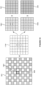
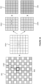
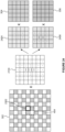
- Figure 3 shows the input pixels 302 being represented in two input blocks 304 and 306.
- the first input block 304 comprises the input pixels having locations corresponding to locations within odd rows of the repeating quincunx arrangement of upsampled pixel locations (illustrated with line hatching in Figure 3 )
- the second input block 306 comprises the input pixels having locations corresponding to locations within even rows of the repeating quincunx arrangement of upsampled pixel locations (illustrated with cross-hatching in Figure 3 ).
- Using the two input blocks 304 and 306 means that the inputs are denser than if the input pixels were received as a block having the repeating quincunx arrangement, as represented as 302 in Figure 3 .
- Some of the super resolution techniques described in examples herein implement upsampling and adaptive sharpening.
- a memory for storing an upsampled image prior to applying adaptive sharpening is not needed.
- the upsampling and sharpening processes can be combined into a unified process. This can be achieved by applying a sharp upsampling kernel to the input pixels, where the sharp upsampling kernel represents a result of convolving an interpolation kernel with a sharpening kernel.
- the sharp upsampling kernel can be deconstructed into a first set of one or more kernels to be applied to the first input block and a second set of one or more kernels to be applied to the second input block.
- An adaptive sharpening process described herein does not need to alter the weights in the kernels applied to blocks of input pixels in order to alter the amount of sharpening that is applied to different regions of output pixels. This is achieved by obtaining both: (i) a block of non-sharp upsampled pixels, and (ii) a block of sharp upsampled pixels, and then performing weighted sums of the corresponding pixels in the two blocks of upsampled pixels in order to determine a block of output pixels to which adaptive sharpening has been applied.
- This adaptive sharpening is achieved by means of determining the weights of each weighted sum based on an indication of contrast for the corresponding block of input pixels.
- the format of the pixels could be different in different examples.
- the pixels could be in YUV format (in which each pixel has a value in each of Y, U and V channels), and upsampling may be applied to each of the Y, U and V channels separately.
- the upsampling described herein may be applied to just the Y channel, with the upsampling of the U and V channels being performed in a simpler manner, e.g. using bilinear interpolation.
- the upsampling described herein may be applied to each of the Y, U and V channels.
- results from some or all of the computation e.g.
- the origin of the input pixels does not affect the upsampling process described herein.
- the input pixels may be captured (e.g. by a camera) or may be computer-generated (e.g. rendered by a Graphics Processing Unit (GPU) to represent an image of a scene using a rendering technique such as rasterization or ray tracing).
- a GPU may render all of the input pixels for the image region, i.e. all of the input pixels in the repeating quincunx arrangement shown in Figure 4 .
- the upsampling will double the number of pixels. Therefore, in this example, the GPU can render half the number of pixels in the final (upsampled) image, which allows the GPU to have reduced latency, power consumption and/or silicon area compared to a GPU that renders all of the pixels of the final image.
- a temporal resampling process can use motion vectors to estimate input pixels for a current frame based on rendered pixels of the previous frame (e.g. the immediately preceding frame).
- the input pixels of the first of the input blocks 304 may be rendered for the current frame
- the input pixels of the second of the input blocks 306 may be determined by performing temporal resampling on pixels of a previous frame (e.g. the immediately preceding frame) using motion vectors.
- the input pixels 704 are represented in two input blocks (e.g. 304 and 306).
- input pixels 704 1,1 , 704 1,2 , 704 1,3 and 704 1,4 which are shown with line hatching, are part of the first input block 304; whereas input pixels 704 2,1 , 704 2,2 , 704 2,3 and 704 2,4 , which are shown with cross hatching, are part of the second input block 306.
- step S604 the pixel determination logic 406 applies one or more second kernels (which may be referred to as vertical kernels) to at least a second subset of the input pixels to determine a vertical component.
- a kernel of 0.5 0.5 can be applied to the input pixels which are vertically adjacent and either side of the upsampled pixel location for which an upsampled pixel is being determined.
- the vertical kernel is applied to pixels 704 2,2 and 704 2,4 from input block 2.
- step S604 is performed for the upsampled pixel denoted "BL” in Figure 7 then the vertical kernel is applied to pixels 704 1,1 and 704 1,3 from input block 1.
- h [ p 1,1 , p 1,2 ], where p 1,1 is the value of input pixel 704 1,1 and p 1,2 is the value of input pixel 704 1,2 .
- h [ p 2,3 , p 2,4 ], where p 23 is the value of input pixel 704 2,3 and p 2,4 is the value of input pixel 704 2,4 .
- Figure 8b shows a 3x3 kernel 804 (which may be implemented as a 3x1 kernel) which can be applied to the input pixels 702 to represent the effect of performing steps S604 and S608 for an upsampled pixel location being determined.
- the kernel 804 could be centred on the upsampled pixel being determined and applied to the input pixels 702 such that the result would be given by the dot product b 2 b 2 .
- v where v is a vector of the vertically adjacent pixel values.
- v [ p 2,2 , p 2,4 ], where p 2,2 is the value of input pixel 704 2,2 and p 2,4 is the value of input pixel 704 2,4 .
- v [ p 1,1 , p 1,3 ], where p 1,1 is the value of input pixel 704 1,1 and p 1,3 is the value of input pixel 704 1,3 .
- steps S602 to S610 can be summarised as determining the upsampled pixels denoted TR and BL as the sum of dot products: a 2 a 2 . h + b 2 b 2 . v , where h and v are vectors of adjacent pixel values as described above for the TR and BL pixels respectively.
- the values of the weighting parameters, a and b are set in dependence on the local context, such that by determining the upsampled pixels in step S506 in accordance with the determined weighting parameters the upsampled pixels are determined in accordance with the relative horizontal and vertical variation of the input pixels within the image region.
- the weighting parameters can be used to reduce artefacts and blurring over anisotropic features (e.g. edges) in the image, which may otherwise result from an upsampling process.
- the weighting parameter determination logic 408 analyses the input pixels in step S504 to determine the one or more weighting parameters.
- the neural network may be hardcoded into a hardware implementation of the neural network, that is, the neural network may be implemented directly in silicon, rather than being run on more general hardware (NNA, GPU, CPU etc.) by means of software).
- the neural network has been trained, e.g. using Quantization Aware Training (QAT), to output an indication of the one or more weighting parameters indicative of relative horizontal and vertical variation of the input pixels within the image region.
- QTT Quantization Aware Training
- the implementation of the neural network 900 is configured to receive the input pixels 902, process the input pixels to determine an indication of the one or more weighting parameters, and output the determined indication of the one or more weighting parameters for use in applying upsampling to the input pixels representing the image region to determine a block of upsampled pixels.
- the input pixels are represented in two input blocks, wherein one of the two input blocks comprises the input pixels having locations corresponding to locations within odd rows of a repeating quincunx arrangement of upsampled pixel locations, and the other of the two input blocks comprises the input pixels having locations corresponding to locations within even rows of the repeating quincunx arrangement of upsampled pixel locations.
- each of the input blocks is a 5x5 block of input pixels, such that the input pixels 902 are shown as a 5x5x2 array to indicate that the input pixels are organised as two 5x5 input blocks of input pixels.
- the neural network is trained to output an indication of the one or more weighting parameters to be indicative of relative horizontal and vertical variation of the input pixels within the image region, rather than attempting to train the neural network to output the upsampled pixels themselves.
- a neural network is well suited to determining suitable weighting parameters to represent the relative horizontal and vertical variation of anisotropic image features within the image region, and this task can be achieved with a small neural network.
- the complexity of the implementation of the neural network 900 is low, so it can have a small silicon area, and low latency and power consumption.
- the implementation of the neural network 900 comprises a first convolution layer 906, a first rectified linear unit (ReLU) 908, a second convolution layer 914, a second ReLU 916 and a third convolution layer 920.
- convolution layers and ReLUs are simple to implement.
- the first ReLU 908 is implemented between the first convolution layer 906 and the second convolution layer 914
- the second ReLU 916 is implemented between the second convolution layer 914 and the third convolution layer 920.
- the neural network may be implemented in hardware (e.g. in fixed function circuitry), software, or a combination thereof.
- Figure 10 is a flow chart for a method of determining an indication of the weighting parameter(s) using the implementation of the neural network 900.
- step S1002 the input pixels 902 are received at the implementation of the neural network 900.
- step S1004 the first convolution layer 906 is used to determine a first intermediate tensor based on the input pixels 902.
- the first ReLU 908 is used to set negative values in the first intermediate tensor to zero.
- the first ReLU 908 could be implemented trivially by combining with the preceding convolution, e.g. by AND-ing the result of the preceding convolution with the NOT of the sign bit.
- the first intermediate tensor 912 output from the first ReLU 908 is shown in Figure 9 .
- the first intermediate tensor 912 extends in only one of a horizontal dimension and a vertical dimension with respect to the dimensions of the image region represented by the input pixels 902.
- the first intermediate tensor 912 extends in only a horizontal dimension (and not a vertical dimension), e.g. where the processing is performed along the rows of the image. However, in other examples, the first intermediate tensor could extend in only a vertical dimension (and not a horizontal dimension), e.g. if the processing were to be performed down the columns of the image. In the example shown in Figure 9 , the first intermediate tensor 912 is a 5x1x16 array.
- the second convolution layer 914 is used to determine a second intermediate tensor based on the first intermediate tensor 912. To save computation, this layer may be a depthwise convolution, i.e. processing each channel of the input separately without a cross-channel component to the operation.
- the second ReLU 916 is used to set negative values in the second intermediate tensor to zero.
- the second intermediate tensor 918 output from the second ReLU 916 is shown in Figure 9 .
- the second intermediate tensor does not extend in either the horizontal dimension or the vertical dimension with respect to the dimensions of the image region represented by the input pixels 902.
- the second intermediate tensor 918 is a 1x1x16 array.
- the third convolution layer 920 is used to determine the indication of the one or more weighting parameters 922 based on the second intermediate tensor 918.
- the indication of the one or more weighting parameters 922 is shown in Figure 9 as a 1x1x1 array (i.e. a scalar value for each input region).
- the indication of the one or more weighting parameters 922 may be the value of the first weighting parameter a described herein, where the value of the second weighting parameter b is inferred from the value of a , as 1 - a.
- the indication of the one or more weighting parameters may be treated as if it were dy or dx, or the quantity
- the indication of the one or more weighting parameters may be a 1x1x2 array (i.e. there may be two output channels), representing two values of the weighting parameter, a , for separate use for two different pixel locations (e.g. the top right and bottom left pixel locations of a 2x2 block of pixel locations).
- this network performs 256 MACs per output block, which is significantly lower than typical upsampling neural networks, which typically require many orders of magnitude more operations for the same output resolution.
- Further significant savings are possible by removing unused channels from the trained network, and using low-precision integer arithmetic by means of QAT. Such savings translate directly into lower area, power and latency requirements when implemented in fixed-function hardware.
- step S1014 the determined indication of the one or more weighting parameters 922 (e.g. the value of a ) is output from the implementation of the neural network 900, e.g. output from the weighting parameter determination logic 408 and provided to the pixel determination logic 406 for use in upsampling as described herein.
- the output value a may be constrained to lie between 0 and 1, for example by means of a sigmoid activation function.
- the image region is part of an input image, wherein the upsampling is to be performed iteratively for a plurality of partially overlapping image regions within the input image.
- each of the image regions can be thought of as a window that slides across the input image.
- some of the input pixels 902 of a current image region are the same as some of the input pixels of a previous image region.
- the 'previous image region' may be the image region that was processed in the preceding iteration.
- the processing of the input pixels with the implementation of the neural network 900 may further comprise storing the first intermediate tensor 912 in a buffer which functions as a queue/shift register.
- the first convolution layer 906 may operate on input pixels (e.g. shown with hatching and denoted 904 in Figure 9 ) within a first portion of the current image region that does not overlap with a previous image region, but does not need to operate on input pixels (i.e. the rest of the input pixels 902 which are not shown with hatching in Figure 9 ) within a second portion of the current image region that does overlap with the previous image region.
- the use of the buffer for storing the first intermediate tensor 912 means that the first convolution layer 906 can avoid performing an entire convolution of all of the input pixels, and can instead reuse values that were determined in one or more previous iterations.
- the window may slide by one pixel position in both of the input blocks, such that the second portion of the current image region 904 is a line (e.g. a column or a row) of pixels in both of the input blocks.
- the overlapping region i.e. the first portion of the current image region 904 is a 5x4 block of input pixels in each of the input blocks. It can be appreciated that in this case most of the input pixels of the current image region overlap with input pixels of the previous image region.
- the second portion of the image region 904 is a column of input pixels from each of the input blocks and since the first convolution layer 906 removes the vertical extent from the first intermediate tensor 912 without removing horizontal extent from the first intermediate tensor 912, the first convolution layer does not need to operate on the input pixels in the first portion of the image region.
- the second portion 904 is shown on the left of the image region 902 which would be appropriate when the processing proceeds in a right-to-left order; whereas in other examples, the second portion could be on the right of the image region which would be appropriate if the processing were to proceed in a left-to-right order.
- the window may slide vertically rather than horizontally such that the nonoverlapping portion of the input pixels is a row of input pixels from each of the input blocks, and in this case the first convolution layer could remove the horizontal extent from the first intermediate tensor without removing vertical extent from the first intermediate tensor, such that the first convolution layer would again not need to operate on the input pixels in the overlapping portion of the input pixels.
- the second portion could be at the bottom of the image region which would be appropriate if the processing were to proceed in a top-to-bottom order; whereas in other examples, the second portion could be at the top of the image region which would be appropriate if the processing were to proceed in a bottom-to-top order.
- the implementation of the neural network does not comprise any linestores.
- Linestores store lines (e.g. rows) of pixel values, and require large memories. By avoiding including any linestores in the implementation of the neural network 900 the silicon area and the power consumption of the implementation of the neural network can be kept low.
- N-times higher throughput could be achieved by implementing N instances of the neural network in fixed-function hardware. These instances would operate on adjacent input regions.
- the value of N may be a configuration option.
- the neural network can be trained using Quantization Aware Training (QAT).
- QAT Quantization Aware Training
- the neural network can be trained for sparsity and low bit depths. Any MACs for missing weights can be skipped (i.e. not synthesised).
- the implementation of the neural network 900 does not need to use the same bit depth for all layers or weights within a layer, and the QAT scheme can be used to optimise the layers and weights of the neural network appropriately.
- the neural network is defined using coefficients (e.g. the weights).
- the neural network may be hardcoded in hardware (e.g. hardcoded in silicon) of the implementation of the neural network.
- each coefficient of the neural network may be compressed individually, e.g. individual coefficient bit depths are possible.
- Each of the coefficients may be determined to have a low bit-depth, and the bit depths of the coefficients may be determined individually, e.g. learned/trained individually, thereby allowing for more optimal (i.e. smaller) bit-depths to be used (compared to determining a shared bit depth for an entire layer or channel of the neural network).
- Each of the coefficients may be removed from the network, e.g. by means of training for sparsity.
- multipliers corresponding to an eliminated coefficient would simply be excluded from the implementation, meaning no power or area is consumed, and a silicon multiplier corresponding to a low bit depth weight may be reduced in area and power consumption.
- a silicon multiplier corresponding to a low bit depth weight may be reduced in area and power consumption.
- the latency, power consumption and/or silicon area of the implementation of the neural network can be reduced.
- coefficients with a zero value or with a value that is closer to zero than a threshold
- sparsity can be implemented in an unstructured, per-coefficient manner, which would ordinarily be hard to exploit. This may allow entire multiplies to be skipped.
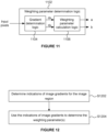
- FIG. 11 shows weighting parameter determination logic 1102 which is configured to analyse the input pixels and output an indication of one or more weighting parameters
- Figure 12 is a flow chart for a method of determining the weighting parameter(s) using the weighting parameter determination logic 1102.
- the weighting parameter determination logic 1102 comprises gradient determination logic 1104 and weighting parameter calculation logic 1106.
- the pixel determination logic 1300 For each sharpened upsampled pixel in the block of sharpened upsampled pixels 1310 the pixel determination logic 1300: (i) in step S1404, applies a first set of one or more kernels to input pixels of the first input block 1304 1 ; (ii) in step S1406, applies a second set of one or more kernels to input pixels of the second input block 1304 2 ; and (iii) in step S1408, combines the results of applying the first set of one or more kernels and applying the second set of one or more kernels to determine the sharpened upsampled pixel.
- Each of the kernels 1306 is configured to perform upsampling and sharpening. In other words, sharpening and upsampling (e.g.
- step S2204 the pixel determination logic 1300 determines a vertical component by summing the result of applying the first vertical kernel to the input pixels of the first input block 304 (in step S1404) with the result of applying the second vertical kernel to the input pixels of the second input block 306 (in step S1406). Steps S2202 and S2204 may be performed in series or in parallel. The pixel determination logic 1300 can then combine the determined horizontal and vertical components (e.g. by performing steps S2206, S2208 and S2210) to determine the sharpened upsampled pixel.
- step S2206 the pixel determination logic 1300 multiplies the horizontal component (determined in step S2202) by a first weighting parameter (e.g. the weighting parameter a described above) to determine a weighted horizontal component.
- step S2208 the pixel determination logic 1300 multiplies the vertical component (determined in step S2204) by a second weighting parameter (e.g. the weighting parameter b described above) to determine a weighted vertical component.
- Steps S2206 and S2208 may be performed in series or in parallel.
- step S2210 the pixel determination logic sums the weighted horizontal component and the weighted vertical component to determine the sharpened upsampled pixel.
- the weighting parameters are determined by analysing the input pixels of the first and second input blocks 304 and 306, and are indicative of relative horizontal and vertical variation of the input pixels.
- an implementation of a neural network 900 may be used to determine an indication of the weighting parameters to be indicative of the relative horizontal and vertical variation of the input pixels. Using these weighting parameters to weight the sum of the horizontal and vertical components reduces blurring and other artefacts in the sharpened upsampled pixels representing anisotropic image features, such as edges, texture and high frequency content.
- Figure 23 illustrates how the full horizontal sharp upsampling kernel 2004 can be deconstructed into: (i) a kernel 2304 to be applied to the first input block of input pixels 304, and (ii) a kernel 2306 to be applied to the second input block of input pixels 306, for use in determining the horizontal component for the sharpened upsampled pixel in the top right of the block of sharpened upsampled pixels 404.
- the sharpened upsampled pixel in the top right of the block of sharpened upsampled pixels 404 has a location which corresponds to a location 2302 which is horizontally adjacent to two input pixels of the first input block 304 and vertically adjacent to two input pixels of the second input block 306.
- the kernel 2004 would be centred on the location 2302 and values of the kernel 2004 would be multiplied with input pixels at corresponding surrounding locations and the results would be summed. It can be seen that doing this would mean that values of the kernel 2004 would be multiplied with some, but not all, of the input pixels of the first input block 304 shown with line hatching in Figure 23 .
- the kernel 2304 includes those values of kernel 2004 that would be multiplied with input pixels of the first input block 304.
- values of the kernel 2004 would be multiplied with some, but not all, of the input pixels of the second input block 306 shown with cross hatching in Figure 23
- the kernel 2306 includes those values of kernel 2004 that would be multiplied with input pixels of the second input block 306.
- the first horizontal kernel 2304 has a first subset of values of the full horizontal sharp upsampling kernel 2004 (i.e. the values of the full horizontal sharp upsampling kernel 2004 at locations corresponding to the locations of the input pixels in the first input block 304)
- the second horizontal kernel 2306 has a second subset of values of the full horizontal sharp upsampling kernel 2004 (i.e.
- Figure 24 illustrates how the full vertical sharp upsampling kernel 2104 can be deconstructed into: (i) a kernel 2404 to be applied to the first input block of input pixels 304, and (ii) a kernel 2406 to be applied to the second input block of input pixels 306, for use in determining the vertical component for the sharpened upsampled pixel in the top right of the block of sharpened upsampled pixels 404.
- the sharpened upsampled pixel in the top right of the block of sharpened upsampled pixels 404 has a location which corresponds to the location 2302.
- steps S2206, S2208 and S2210 are performed for determining the sharpened upsampled pixel in the top right of the block of sharpened upsampled pixels 404, wherein: (i) step S2206 comprises multiplying the horizontal component (determined as described above with reference to Figure 23 ) by the first weighting parameter, a , to determine a weighted horizontal component; (ii) step S2208 comprises multiplying the vertical component (determined as described above with reference to Figure 24 ) by the second weighting parameter, b , to determine a weighted vertical component; and (iii) step S2210 comprises summing the weighted horizontal component and the weighted vertical component determined in steps S2206 and S2208 to determine the sharpened upsampled pixel in the top right of the block of sharpened upsampled pixels 404.
- the kernel 2004 would be centred on the location 2502 and values of the kernel 2004 would be multiplied with input pixels at corresponding surrounding locations and the results would be summed. It can be seen that doing this would mean that values of the kernel 2004 would be multiplied with some, but not all, of the input pixels of the first input block 304 shown with line hatching in Figure 25 .
- the kernel 2504 includes those values of kernel 2004 that would be multiplied with input pixels of the first input block 304.
- the kernel 2506 may be implemented as a 3x4 kernel (with the zero padding around the top, bottom and right edges of the 5x5 kernel 2506 shown in Figure 25 removed) which can then be applied to the corresponding 3x4 region of the 5x5 input block 306, which is on the left of the second, third and fourth rows of input pixels within the input block 306.
- the kernels 2504 and 2506 correspond to the pair of kernels 1306 HBL in Figure 13 .
- the kernel 2104 would be centred on the location 2502 and values of the kernel 2104 would be multiplied with input pixels at corresponding surrounding locations and the results would be summed. It can be seen that doing this would mean that values of the kernel 2104 would be multiplied with some, but not all, of the input pixels of the first input block 304 shown with line hatching in Figure 26 .
- the kernel 2604 includes those values of kernel 2104 that would be multiplied with input pixels of the first input block 304.
- values of the kernel 2104 would be multiplied with some, but not all, of the input pixels of the second input block 306 shown with cross hatching in Figure 26
- the kernel 2606 includes those values of kernel 2104 that would be multiplied with input pixels of the second input block 306.
- the first vertical kernel 2604 has a first subset of values of the full vertical sharp upsampling kernel 2104 (i.e. the values of the full vertical sharp upsampling kernel 2104 at locations corresponding to the locations of the input pixels in the first input block 304)
- the second vertical kernel 2606 has a second subset of values of the full vertical sharp upsampling kernel 2104 (i.e.
- Figure 26 shows the kernels 2604 and 2606 being padded with zeros up to 5 ⁇ 5 kernels.
- the zero padding may not be implemented in hardware.
- the zero padding shown in Figure 26 is for the clarity of this explanation, as a way of indicating the correct alignment of the kernels with respect to the 5 ⁇ 5 input blocks to which they will be applied.
- the kernel 2604 may be implemented as a 4 ⁇ 3 kernel (with the zero padding around the top, left and right edges of the 5 ⁇ 5 kernel 2604 shown in Figure 26 removed) which can then be applied to the corresponding 4 ⁇ 3 region of the 5 ⁇ 5 input block 304, which is at the bottom of the second, third and fourth columns of input pixels within the input block 304.
- the kernel 2606 may be implemented as a 3 ⁇ 2 kernel (with the zero padding around the top, bottom and left edges and down the rightmost two columns of the 5 ⁇ 5 kernel 2606 shown in Figure 26 removed) which can then be applied to the corresponding 3 ⁇ 2 region of the 5 ⁇ 5 input block 306, which is in the second and third columns of the second, third and fourth rows of input pixels within the input block 306.
- the kernels 2604 and 2606 correspond to the pair of kernels 1306 VBL in Figure 13 .
- steps S2206, S2208 and S2210 are performed for determining the sharpened upsampled pixel in the bottom left of the block of sharpened upsampled pixels 404, wherein: (i) step S2206 comprises multiplying the horizontal component (determined as described above with reference to Figure 25 ) by the first weighting parameter, a , to determine a weighted horizontal component; (ii) step S2208 comprises multiplying the vertical component (determined as described above with reference to Figure 26 ) by the second weighting parameter, b , to determine a weighted vertical component; and (iii) step S2210 comprises summing the weighted horizontal component and the weighted vertical component determined in steps S2206 and S2208 to determine the sharpened upsampled pixel in the bottom left of the block of sharpened upsampled pixels 404.
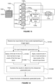
- Figure 27 illustrates an adaptive sharpening unit 2700 configured to apply adaptive sharpening to input pixels 2702 representing an image region to determine a block of output pixels 2724, e.g. for use in implementing a super resolution technique.
- the input pixels 2702 are represented with two input blocks 2706 and 2708, which correspond to the input blocks 304 and 306 described above.
- one of the two input blocks e.g. input block 2706
- the other of the two input blocks e.g. input block 2708 comprises input pixels having locations corresponding to locations within even rows of the repeating quincunx arrangement of upsampled pixel locations.
- the block of output pixels 2724 corresponds to a location 2704 in the centre of the input pixels 2702.
- the adaptive sharpening unit 2700 comprises: non-sharp pixel determination logic 2710 (which may be considered to be a first processing module) configured to process the input pixels and output a block of non-sharpened upsampled pixels 2712 for the image region as described above; weighting parameter determination logic 2714 configured to determine one or more weighting parameters as described above (e.g. comprising the implementation of the neural network 900); sharp pixel determination logic 2716 (which may be considered to be a second processing module) configured to process the input pixels and output a block of sharpened upsampled pixels 2712 for the image region as described above; contrast determination logic 2720; and output pixel determination logic 2722.
- non-sharp pixel determination logic 2710 (which may be considered to be a first processing module) configured to process the input pixels and output a block of non-sharpened upsampled pixels 2712 for the image region as described above
- Figure 28 is a flow chart for a method of applying adaptive sharpening to the input pixels 2702 representing the image region to determine the block of output pixels 2724, e.g. for use in implementing a super resolution technique.
- step S2804 the weighting parameter determination logic 2714 analyses the input pixels to determine one or more weighting parameters indicative of the relative horizontal and vertical variation of the input pixels within the image region, as described above.
- the weighting parameter determination logic 2714 may comprise an implementation of the neural network 900 described above.
- An indication of the weighting parameter(s) is provided to the non-sharp pixel determination logic 2710 and to the sharp pixel determination logic 2716.
- the non-sharp pixel determination logic 2710 determines a block of non-sharpened upsampled pixels 2712 based on the input blocks of input pixels as described above. As described above, the non-sharpened upsampled pixels are determined in accordance with the relative horizontal and vertical variation of the input pixels within the image region indicated by the weighting parameter(s).
- the output pixels of the block of output pixels 2724 are upsampled pixels (relative to the input pixels 2702).
- the block of non-sharpened upsampled pixels 2712 represents a non-sharp version of the block of output pixels 2724.
- the block of non-sharpened upsampled pixels 2712 is passed to, and received by, the output pixel determination logic 2722.
- the sharp pixel determination logic 2716 determines a block of sharpened upsampled pixels 2718 based on the input blocks of input pixels as described above. As described above, the non-sharpened upsampled pixels are determined in accordance with the relative horizontal and vertical variation of the input pixels within the image region indicated by the weighting parameter(s).
- the block of sharpened upsampled pixels 2718 represents a sharp version of the block of output pixels 2724.
- the block of sharp upsampled pixels may be a sharp version of the block of output pixels.
- the block of sharpened upsampled pixels 2718 is passed to, and received by, the output pixel determination logic 2722.
- the contrast determination logic 2720 determines an indication of contrast for the image region based on the input pixels 2702.
- contrast determination logic 2720 may determine indications of contrast for the image region using a window of input pixels wherein the window of input pixels covers at least a region covered by the block of output pixels.
- the pixel values may be pixel values from the Y channel (i.e. the luminance channel). Any suitable indication of contrast could be determined.
- the contrast determination logic 2720 could identify a minimum pixel value and a maximum pixel value within a window of input pixels, wherein the window of input pixels covers at least a region represented by the block of output pixels 2724.
- the contrast determination logic 2720 could determine a difference between the identified minimum and maximum pixel values within the window of input pixels, and this determined difference can be used as an indication of contrast for the image region.
- the contrast determination logic 810 could determine a standard deviation or a variance of the input pixel values within a window of input pixels, and this determined standard deviation or variance can be used as an indication of contrast for the image region.
- the determined indication of contrast for the image region is passed to, and received by, the output pixel determination logic 2722. Steps S2806, S2808 and S2810 could be performed in any order, and two or more of these steps could be performed in parallel.
- step S2812 the output pixel determination logic 2722 determines each of the output pixels of the block of output pixels 2724 by performing a respective weighted sum of: (i) a corresponding non-sharpened upsampled pixel in the block of non-sharpened upsampled pixels 2712 and (ii) a corresponding sharpened upsampled pixel in the block of sharpened upsampled pixels 2718.
- the weights of the weighted sums are based on the determined one or more indications of contrast for the image region. For example, the output pixel determination logic 2722 may determine two weights: w non-sharp and w sharp .
- the first weight, w non-sharp is to be used for weighting non-sharp upsampled pixels in the weighted sums performed by the output pixel determination logic 2722.
- the second weight, w sharp is to be used for weighting sharp upsampled pixels in weighted sums performed by the output pixel determination logic 2722.
- w non-sharp + w sharp 1.
- both w non-sharp and w sharp are in a range from 0 to 1.
- a sharpness boost may be applied by setting w sharp to be greater than 1.
- w sharp may be allowed to go above 1 and w non-sharp to go below 0, which can be used to achieve a sharpness boost.
- the weights ( w non-sharp and w sharp ) are still be constrained to sum to 1.
- the sharpness boost, ⁇ can be exposed as a tuneable parameter, and may take a value equal to, above or below 1.
- Setting ⁇ > 1 will increase the sharpness of the output pixels, whereas setting ⁇ ⁇ 1 will attenuate the sharpness of the output pixels.
- the output pixels may be sharper than the sharp upsampled pixels.
- the sharp upsampled pixels may still be considered to be a sharp version of the output pixels as increasing w sharp results in a corresponding increase in the sharpness of the output pixels.
- ⁇ is set to be 1. Setting ⁇ to be negative is possible and would mean that the image is blurred rather than sharpened.
- the first weight, w non_sharp is larger than the second weight, w sharp , when the indicated contrast is relatively high (e.g. when the indicated contrast is between 0.5 and 1, if 0 is the minimum possible indicated contrast and 1 is the maximum possible indicated contrast); whereas the first weight, w non-sharp , is smaller than the second weight, w sharp , when the indicated contrast is relatively low (e.g. when the indicated contrast is between 0 and 0.5, if 0 is the minimum possible indicated contrast and 1 is the maximum possible indicated contrast).
- the block of output pixels 2724 will be more similar to the block of non-sharp upsampled pixels 2712 than to the block of sharp upsampled pixels 2718 (because w non-sharp > w sharp ) such that overshoot artefacts caused by sharpening regions of high contrast are reduced; whereas for regions with low contrast the block of output pixels 2724 will be more similar to the block of sharp upsampled pixels 2718 than to the block of non-sharp upsampled pixels 2712 (because w non-sharp ⁇ w sharp ) such that apparent detail in low contrast regions is enhanced.
- the block of non-sharp upsampled pixels 2712 determined by the non-sharp pixel determination logic 2710, the block of sharp upsampled pixels 2718 determined by the sharp pixel determination logic 2716, and the block of output pixels 2724 are all 2x2 blocks.
- the top left output pixel of the block of output pixels 2724 is determined by summing: (i) the result of multiplying the top left non-sharp upsampled pixel of the block of non-sharp upsampled pixels 2712 by the weight w non_sharp , and (ii) the result of multiplying the top left sharp upsampled pixel of the block of sharp upsampled pixels 2718 by the weight w sharp .
- the top right output pixel of the block of output pixels 2724 is determined by summing: (i) the result of multiplying the top right non-sharp upsampled pixel of the block of non-sharp upsampled pixels 2712 by the weight w non_sharp , and (ii) the result of multiplying the top right sharp upsampled pixel of the block of sharp upsampled pixels 2718 by the weight w sharp .
- the bottom left output pixel of the block of output pixels 2724 is determined by summing: (i) the result of multiplying the bottom left non-sharp upsampled pixel of the block of non-sharp upsampled pixels 2712 by the weight w non_sharp , and (ii) the result of multiplying the bottom left sharp upsampled pixel of the block of sharp upsampled pixels 2718 by the weight w sharp .
- the bottom right output pixel of the block of output pixels 2724 is determined by summing: (i) the result of multiplying the bottom right non-sharp upsampled pixel of the block of non-sharp upsampled pixels 2712 by the weight w non-sharp , and (ii) the result of multiplying the bottom right sharp upsampled pixel of the block of sharp upsampled pixels 2718 by the weight w sharp .
- step S3012 the update logic 2910 updates one or more parameters of the neural network based on a result of the comparing performed in step S3010 (i.e. based on the indications of the errors).
- the one or more parameters of the neural network are updated based on the calculated indication of the errors. In this way, on average, with an appropriate choice of cost function and learning rate, subsequent errors in a subsequent iteration are less than the indicated errors in the current iteration.
- the one or more parameters of the neural network which may be updated include parameters such as weights used in the convolution layers and bit depths of values in the neural network.
Landscapes
- Engineering & Computer Science (AREA)
- Physics & Mathematics (AREA)
- General Physics & Mathematics (AREA)
- Theoretical Computer Science (AREA)
- Artificial Intelligence (AREA)
- Evolutionary Computation (AREA)
- Multimedia (AREA)
- Signal Processing (AREA)
- Image Processing (AREA)
- Apparatus For Radiation Diagnosis (AREA)
Applications Claiming Priority (1)
| Application Number | Priority Date | Filing Date | Title |
|---|---|---|---|
| GB2319651.2A GB2636743A (en) | 2023-12-20 | 2023-12-20 | Upsampling |
Publications (1)
| Publication Number | Publication Date |
|---|---|
| EP4575974A1 true EP4575974A1 (de) | 2025-06-25 |
Family
ID=89662541
Family Applications (2)
| Application Number | Title | Priority Date | Filing Date |
|---|---|---|---|
| EP24220664.7A Pending EP4575973A3 (de) | 2023-12-20 | 2024-12-17 | Upsampling |
| EP24220674.6A Pending EP4575974A1 (de) | 2023-12-20 | 2024-12-17 | Upsampling |
Family Applications Before (1)
| Application Number | Title | Priority Date | Filing Date |
|---|---|---|---|
| EP24220664.7A Pending EP4575973A3 (de) | 2023-12-20 | 2024-12-17 | Upsampling |
Country Status (4)
| Country | Link |
|---|---|
| US (1) | US20250322491A1 (de) |
| EP (2) | EP4575973A3 (de) |
| CN (1) | CN120182090A (de) |
| GB (1) | GB2636743A (de) |
Citations (2)
| Publication number | Priority date | Publication date | Assignee | Title |
|---|---|---|---|---|
| US20130113884A1 (en) * | 2010-07-19 | 2013-05-09 | Dolby Laboratories Licensing Corporation | Enhancement Methods for Sampled and Multiplexed Image and Video Data |
| GB2617220A (en) * | 2022-09-30 | 2023-10-04 | Imagination Tech Ltd | Upsampling blocks of pixels |
-
2023
- 2023-12-20 GB GB2319651.2A patent/GB2636743A/en active Pending
-
2024
- 2024-12-17 EP EP24220664.7A patent/EP4575973A3/de active Pending
- 2024-12-17 EP EP24220674.6A patent/EP4575974A1/de active Pending
- 2024-12-18 CN CN202411870406.5A patent/CN120182090A/zh active Pending
- 2024-12-20 US US18/990,463 patent/US20250322491A1/en active Pending
Patent Citations (2)
| Publication number | Priority date | Publication date | Assignee | Title |
|---|---|---|---|---|
| US20130113884A1 (en) * | 2010-07-19 | 2013-05-09 | Dolby Laboratories Licensing Corporation | Enhancement Methods for Sampled and Multiplexed Image and Video Data |
| GB2617220A (en) * | 2022-09-30 | 2023-10-04 | Imagination Tech Ltd | Upsampling blocks of pixels |
Also Published As
| Publication number | Publication date |
|---|---|
| EP4575973A3 (de) | 2025-07-09 |
| EP4575973A2 (de) | 2025-06-25 |
| CN120182090A (zh) | 2025-06-20 |
| US20250322491A1 (en) | 2025-10-16 |
| GB202319651D0 (en) | 2024-01-31 |
| GB2636743A (en) | 2025-07-02 |
Similar Documents
| Publication | Publication Date | Title |
|---|---|---|
| Zhao et al. | GUN: Gradual upsampling network for single image super-resolution | |
| US8457429B2 (en) | Method and system for enhancing image signals and other signals to increase perception of depth | |
| CN115908156B (zh) | 渲染3d场景的图像的方法、图形处理单元和存储介质 | |
| US8417050B2 (en) | Multi-scale robust sharpening and contrast enhancement | |
| US8731318B2 (en) | Unified spatial image processing | |
| CN117830145A (zh) | 像素块的自适应锐化 | |
| He et al. | FPGA-based real-time super-resolution system for ultra high definition videos | |
| CN108765282A (zh) | 基于fpga的实时超分辨方法及系统 | |
| CN117830146A (zh) | 像素块的自适应锐化 | |
| EP4575974A1 (de) | Upsampling | |
| EP4345734A1 (de) | Adaptive schärfung für blöcke von hochabgetasteten pixeln | |
| GB2623071A (en) | Adaptive sharpening for blocks of pixels | |
| US20250322490A1 (en) | Weighting parameters for use in applying upsampling | |
| Gabiger et al. | A synchronous FPGA design of a bilateral filter for image processing | |
| US20240135505A1 (en) | Adaptive sharpening for blocks of pixels | |
| CN117217987A (zh) | 图像处理方法、装置、设备及系统 | |
| US20260051024A1 (en) | Upsampling Input Pixels of a Frame Using a Jitter Pattern over a Sequence of Frames | |
| EP4575977A1 (de) | Upsampling | |
| JP7544359B2 (ja) | 最適化装置、訓練装置、合成装置、それらの方法、およびプログラム | |
| CN120689243B (zh) | 一种基于空间-光谱信息增强的遥感图像全色锐化方法 | |
| Shen | Single Image Super-Resolution via Deep Dense Network | |
| Hu et al. | Dual-Stem Transformer for Efficient Image Denoising with Spatial-Channel Attention |
Legal Events
| Date | Code | Title | Description |
|---|---|---|---|
| PUAI | Public reference made under article 153(3) epc to a published international application that has entered the european phase |
Free format text: ORIGINAL CODE: 0009012 |
|
| STAA | Information on the status of an ep patent application or granted ep patent |
Free format text: STATUS: THE APPLICATION HAS BEEN PUBLISHED |
|
| AK | Designated contracting states |
Kind code of ref document: A1 Designated state(s): AL AT BE BG CH CY CZ DE DK EE ES FI FR GB GR HR HU IE IS IT LI LT LU LV MC ME MK MT NL NO PL PT RO RS SE SI SK SM TR |
|
| P01 | Opt-out of the competence of the unified patent court (upc) registered |
Free format text: CASE NUMBER: APP_30949/2025 Effective date: 20250626 |
|
| STAA | Information on the status of an ep patent application or granted ep patent |
Free format text: STATUS: REQUEST FOR EXAMINATION WAS MADE |
|
| 17P | Request for examination filed |
Effective date: 20251217 |