EP4576152A1 - Disjoncteur et procédé d'assemblage d'un mécanisme de commande sur une base moulée de disjoncteur - Google Patents
Disjoncteur et procédé d'assemblage d'un mécanisme de commande sur une base moulée de disjoncteur Download PDFInfo
- Publication number
- EP4576152A1 EP4576152A1 EP24222151.3A EP24222151A EP4576152A1 EP 4576152 A1 EP4576152 A1 EP 4576152A1 EP 24222151 A EP24222151 A EP 24222151A EP 4576152 A1 EP4576152 A1 EP 4576152A1
- Authority
- EP
- European Patent Office
- Prior art keywords
- operating mechanism
- circuit breaker
- molded base
- legs
- molded
- Prior art date
- Legal status (The legal status is an assumption and is not a legal conclusion. Google has not performed a legal analysis and makes no representation as to the accuracy of the status listed.)
- Pending
Links
Images



Classifications
-
- H—ELECTRICITY
- H01—ELECTRIC ELEMENTS
- H01H—ELECTRIC SWITCHES; RELAYS; SELECTORS; EMERGENCY PROTECTIVE DEVICES
- H01H71/00—Details of the protective switches or relays covered by groups H01H73/00 - H01H83/00
- H01H71/02—Housings; Casings; Bases; Mountings
- H01H71/0207—Mounting or assembling the different parts of the circuit breaker
- H01H71/0214—Housing or casing lateral walls containing guiding grooves or special mounting facilities
-
- H—ELECTRICITY
- H01—ELECTRIC ELEMENTS
- H01H—ELECTRIC SWITCHES; RELAYS; SELECTORS; EMERGENCY PROTECTIVE DEVICES
- H01H71/00—Details of the protective switches or relays covered by groups H01H73/00 - H01H83/00
- H01H71/02—Housings; Casings; Bases; Mountings
- H01H71/0207—Mounting or assembling the different parts of the circuit breaker
-
- H—ELECTRICITY
- H01—ELECTRIC ELEMENTS
- H01H—ELECTRIC SWITCHES; RELAYS; SELECTORS; EMERGENCY PROTECTIVE DEVICES
- H01H11/00—Apparatus or processes specially adapted for the manufacture of electric switches
-
- H—ELECTRICITY
- H01—ELECTRIC ELEMENTS
- H01H—ELECTRIC SWITCHES; RELAYS; SELECTORS; EMERGENCY PROTECTIVE DEVICES
- H01H71/00—Details of the protective switches or relays covered by groups H01H73/00 - H01H83/00
- H01H71/02—Housings; Casings; Bases; Mountings
-
- H—ELECTRICITY
- H01—ELECTRIC ELEMENTS
- H01H—ELECTRIC SWITCHES; RELAYS; SELECTORS; EMERGENCY PROTECTIVE DEVICES
- H01H71/00—Details of the protective switches or relays covered by groups H01H73/00 - H01H83/00
- H01H71/08—Terminals; Connections
-
- H—ELECTRICITY
- H01—ELECTRIC ELEMENTS
- H01H—ELECTRIC SWITCHES; RELAYS; SELECTORS; EMERGENCY PROTECTIVE DEVICES
- H01H71/00—Details of the protective switches or relays covered by groups H01H73/00 - H01H83/00
- H01H71/10—Operating or release mechanisms
-
- H—ELECTRICITY
- H01—ELECTRIC ELEMENTS
- H01H—ELECTRIC SWITCHES; RELAYS; SELECTORS; EMERGENCY PROTECTIVE DEVICES
- H01H71/00—Details of the protective switches or relays covered by groups H01H73/00 - H01H83/00
- H01H71/02—Housings; Casings; Bases; Mountings
- H01H71/0207—Mounting or assembling the different parts of the circuit breaker
- H01H71/0221—Majority of parts mounted on central frame or wall
-
- H—ELECTRICITY
- H01—ELECTRIC ELEMENTS
- H01H—ELECTRIC SWITCHES; RELAYS; SELECTORS; EMERGENCY PROTECTIVE DEVICES
- H01H71/00—Details of the protective switches or relays covered by groups H01H73/00 - H01H83/00
- H01H71/10—Operating or release mechanisms
- H01H71/50—Manual reset mechanisms which may be also used for manual release
- H01H71/52—Manual reset mechanisms which may be also used for manual release actuated by lever
- H01H71/522—Manual reset mechanisms which may be also used for manual release actuated by lever comprising a cradle-mechanism
Definitions
- the present invention refers to the field of fixation of the operating mechanisms of electrical contacts.
- the present invention also belongs to the field of fixation of mechanisms for operating contacts to the base of a molded case circuit breaker.
- molded case circuit breakers can have their functioning based on thermal, magnetic, thermomagnetic or even electronic principles, through the movement of electrical contacts, and can be used, above all, to protect electrical circuits exposed to short-circuits and/or electrical overloads generated by electrical current levels that exceed a nominal limit previously established by linking input and outlet terminals, connected to the electrical supply circuit to be protected.
- circuit breakers work fundamentally in a similar way to electrical switches, i.e., work in such a way as to change the electrical conduction state of an electrical circuit between the "on” (ON) and “off” (OFF) states.
- conventional circuit breakers also comprise an operating handle that can be operated by a user.
- the current carrying capacity it is typical for the current carrying capacity to support relatively high values, reaching up to 1600A, or even more.
- circuit breaker handles to remain stationary in a trip position (TRIP) after a fault event, until a new trigger.
- TRIP trip position
- EP 1010187 presents a circuit breaker device that uses screws to fix the internal mechanisms, and it is dependent of the assembly of the body/cover interface before its internal components can be tested.
- US 5023582 in particular, describes an arrangement that aims only to seal the internal mechanisms of circuit breakers and fix the internal components through pins, without worrying about providing a device that can be tested before its complete assembly.
- One of the objectives of the invention is to provide a circuit breaker, according to the characteristics of claim 1 of the attached set of claims.
- Yet another object of the invention is to provide a method of assembling an operating mechanism on a circuit breaker molded case, according to the characteristics of claim 12 of the attached set of claims.
- Another object of the invention is to impede any translation on the X and Y axes, so as to firmly fix the operating mechanism on the molded base and impede its translation and rotation.
- Another objective of the invention is to allow for the performance of functioning and qualification tests in critical tests of submission to driving forces with the product open, before its complete assembly or closing with a cover, without implying changes to the design or expenditure on auxiliary fixing devices or apparatus.
- Another objective of the invention is not to use screws, reinforcement washers, pins, and equivalent fixation elements dedicated to fixation the circuit breaker operating mechanism, and not to deform the molded base.
- Another objective achieved by the present invention is to allow said operating mechanism of said circuit breaker can easily be replaced during maintenance.
- Figure 1 shows, in an upper perspective view, a circuit breaker (100), comprising a molded base (200), an operating mechanism (300), a molded cover (400), and a cover (500).
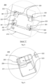
- Figure 2 shows a bottom perspective view of said circuit breaker (100), comprising said molded base (200), molded cover (400), and cap (500) seen in said Figure 1 , highlighting the lower fraction of said molded base (200) which comprises at least one lower region (210), which in turn comprises at least two grooves (220), in addition to an indication of a Detail "F” to be seen in Figure 3 , a transverse axis "X”, a longitudinal axis "Y”, and a lifting axis "Z”.
- Figure 3 presents an enlarged Detail "F” view of said lower region (210) of said molded base (200) of said circuit breaker (100), wherein said molded base (200) (best seen in Figure 2 ) further comprises said plurality of perpendicular walls (221), at least two said shoulders (222) and at least two said inclined surfaces (223). Furthermore, at least one pair of lower ends (361) of said operating mechanism (300) are visible from the grooves (220).
- Figure 4 shows an enlarged view of said groove (220) of the lower region (210) of said molded base (200) previously seen in said Figures 1 to 3 , in which said perpendicular walls (221), said shoulder (222), and said inclined surface (223) are brought to the evidence, in addition to a through opening (224), all visible from said groove (220), through which one of said lower ends (361) of said operating mechanism (300) can pass, after assembly (as seen in Figure 3 ). Furthermore, each of the shoulders (222) in a preferred embodiment has sharp corners.
- FIG. 5 shows a perspective view of said operating mechanism (300) of said circuit breaker (100) according to the present invention, wherein said operating mechanism (300) is an electrical tripping mechanism preferably unipolar, bipolar, tripolar, tetrapolar, among others, commonly known by way of example, which comprises a plurality of side plates (310) placed on opposite sides of said operating mechanism (300), at least one protrusion (320), which projects in the upper portion, perpendicularly to said side plates (310), a plurality of legs (330), preferably four, which extend vertically downwards from each of said side plates (310), in which each said leg (330) comprises a proximal upper portion (340), an intermediate region (350) which is adjacent to the proximal upper portion (340), side tabs (351), comprising a lower edge (352), which form a right angle with the said side tabs (351), that protrude from the intermediate region (350), an upper outer edge of the side plates (310), a distal portion (360) that protrudes
- Said perpendicular protrusion (320) may, e.g., have a cut and folded segment of the side plate (310) or a separate element fixed to the side plate (310) by means of welding and/or an adhesive and/or a screw and/or a rivet and/or other suitable fixation means.
- Said distal portion (360) has a thickness (362) (seen in Figure 6 ), preferably equal to the thickness of the leg (330), the side plate (310), and total length (363).
- Figure 6 shows an enlarged partial view of said leg (330) of said operating mechanism (300) of Figure 5 , where the region close to the upper edge (371) forms a portion or region fold in which a folding line (375) is formed, from which the distal portion (360) assumes the form and function of a tab (364), making it possible to promote the pivoting of said tab (364) and, thus, of at least one of said lower ends (361), around said folding line (375).
- the number of legs (330) may vary in position and quantity, depending on the design of said circuit breaker (100).
- each said leg (330) comprises a thickness (362) to be dimensioned according to the actuating forces, a total length (363) corresponding to the distance between said lower edge (352) and said lower ends (361), a tab (364) which is positioned in the middle or lower region of said legs (330), a width portion (365) determining the width of said tab (364), a through groove (370) in said thickness (362) and placed in the region of said tab (364), an upper edge (371), a lower edge (372), a left edge (373), a right edge (374), wherein the edge (371, 372, 373, 374), both equally opposed and preferably parallel to each other, and, consequently perpendicular to the upper (371) and lower (372) edge, which form a polygon, embodied by way of example, an imaginary folding line (375), which corresponds to the region where the fold of said legs (330) occurs and where said tab (
- Figures 7 and 8 present a cross-sectional side view of said circuit breaker (100) of Figure 1 , showing the operating mechanism (300) fixed on the molded base (200) by introducing the legs (330) of said operating mechanism (300) into the grooves (224) of said molded base (200) (seen in Figure 4 ) and the folds of the tab (364) regions (seen in Figure 6 ) of said legs (330) of said operating mechanism (300), which are folded so as to position the grooves (370) on the shoulders (222) of said molded base (200), wherein said molded base (200) further comprises an angle (225) of inclined surface (223), and wherein additionally after introducing said legs (330) of said operating mechanism (300) and subsequent folding, a conformation angle (366), seen specifically in Figure 8 , is provided to said regions of said tabs (364) of said legs (330).
- Figure 9 shows a lower perspective view of said molded cover (400) of said circuit breaker (100) of Figure 1 , showing some of its internal details, wherein said molded cover (400) comprises a plurality of holes (410) and at least one vertical cutout (420).
- Figure 10 shows a perspective view of the circuit breaker (100) of Figure 1 shown open, without its molded cover (400) or said cap (500), allowing to view into an upper opening of a molded base (200) a plurality of current path poles (230) comprising partition walls (231), a plurality of movable contacts (631), a plurality of fixed contacts (630), means of fixing connection terminals (640) of electrical connection, said operating mechanism (300) in the center and said handle (388), where said handle (388) of said circuit breaker (100) being capable of a translational movement on the "Y" axis in relation to the molded cover (400) and responsive with the driving movement of said elements (383, 384, 385, 386, 387) placed on the "X" axis of said circuit breaker (100) and in an internal rotary trajectory, on a rotating schematic axis "RX", so as to change the electrical conduction state of an electrical circuit between the "ON” and “OFF” states, mechanically driving the closing or opening of said
- Figure 11 shows a longitudinal cross-sectional side view of the region of the partition walls (231) (seen in Figure 10 ) of the circuit breaker (100) of Figure 1 , showing at the lower part the molded base (200), above the molded cover (400), cap (500), in the center the operating mechanism (300), the vertical cutout (420), which presses and retains the perpendicular protrusion (320) of said operating mechanism (300) (also seen in Figure 5 ), limiting a translation of said operating mechanism (300) on the "Y” and "Z” axes.
- a circuit breaker (100) in accordance with the invention comprises at least one molded base (200) that receives and houses at least one operating mechanism (300) and several other operating components, which can receive a electrical supply from conduction lines, having at least one current path pole (230) comprising at least one operating mechanism (300), a fixed contact (630), and at least one movable contact (631) of said circuit breaker (100), so as to interrupt an electrical circuit (seen in Figure 10 ), changing the electrical conduction state between "on” (ON) and "off' (OFF), in case of failure.
- Said circuit breaker (100) has at least one molded cover (400) placed on the molded base (200), and which closes the set and latches said operating mechanism (300) and may optionally have at least one cap (500) placed over said molded cover (400) and a handle (388).
- the molded base (200) comprises at least one lower region (210) provided with at least two, preferably four grooves (220), which, in turn, each comprise at least one perpendicular wall (221) from which at least one shoulder (222) protrudes, at least one through opening (224) placed between said shoulder (222) and said inclined surface (223), through which one of the lower ends (361) of the operating mechanism (300) can pass, after an assembly between them (as seen in Figure 3 ).
- the grooves (220) are open regions that can have any shape and several different sizes, as long as the combination of these allows the ends of instruments (punch, screwdriver or similar) can be introduced and moved at least partially inside the molded base (200) from said grooves (220), and the inclined surface (223) can be used for this purpose.
- the perpendicular wall (221) is a surface that is adjacent to and is preferably perpendicular to the lower region (210) and preferably perpendicular to the projection of the shoulder (222), wherein said perpendicular wall (221) can serve as a stop for the tabs (364) of the legs (330) of the operating mechanism (300), as will be seen later.
- the inclined surface (223) is situated on a surface opposite the perpendicular wall (221) and forms an inclined surface angle (225) with a value between 10° and 70°, preferably between 30° and 60° in relation to said inclined surface angle (225) of the circuit breaker (100).
- the current path poles (230) are chambers that receive and bearing pivotally at least one movable contact (631) that is moved by driving the operating mechanism (300) to put the movable electrical contact (631) into contact or to interrupt it with at least one fixed contact (630), between one side of at least one connection terminal (640) and the other side of said at least one connection terminal (640) of an electrical circuit, on the side opposite to the circuit breaker (100). Furthermore, said current path pole (230) is normally adjacent to an electric arc extinguishing system (not shown), which aims to prevent damage to the equipment caused by the electric arc that forms when the electrical circuit is interrupted in operation resulting from said operating mechanism (300), particularly in the presence of high currents, as is the case with this type of device.
- folding line (375) coincides with the upper edge (371)
- said folding line (375) should, in accordance with the invention, be understood as located in a region preferably adjacent to said upper edge (371), and may therefore coincide or not with said upper edge (371).
- the groove (370) is positioned in the vicinity of the distal portion (360) so that the left edge (373) and right edge (374) have, respectively, a left horizontal edge (376) and a right horizontal edge (377) in relation to the corresponding left and right edges of the tab (364), and so that the upper edge (371) and lower edge (372) have, respectively, a said upper vertical edge (378) and a said lower vertical edge (379) in relation to at least one of the lower ends (361).
- the preferred shape of the groove (370) is the polygonal shape, more preferably the straight polygonal shape, it should be noted that said groove (370) can assume other shapes such as, for example, the circumferential, ellipsoidal, cylindrical shapes, among others, and one or more said grooves (370) of the same said operating mechanism (300) can also have geometries that are the same or different from each other. It should also be noted that said grooves (370) can be either cutouts, through holes, or depressions or low-relief polygons formed by punching or crushing.
- the left horizontal edge (376) and the right horizontal edge (377) each correspond to a value between 5 and 40%, preferably between 10 and 30% of a width portion (365) of the tab (364).
- said horizontal edges (376, 377) should preferably be equal to each other, for the purposes of horizontal centering of the groove (370) in relation to the width portion (365) of said tab (364), said horizontal edges (376, 377) may be different from each other, depending on the design and construction characteristics of said circuit breaker (100).
- the thickness (362) and width portion (365) must be equal to or, preferably, smaller than the corresponding dimensions of the through openings (224), so as to allow the tabs (364) of the operating mechanism (300) to pass through said through openings (224) and remain entirely housed inside the molded base (200), the vertical movement of insertion of said operating mechanism (300) being preferably limited by the lower edge (352), which may vertically touch lower abutment faces (not shown) of said molded base (200).
- the lower vertical region (379) corresponds to a value between 5 and 45%, preferably between 10 and 35% of the total length (363) of the distal portion (360).
- the handle mechanism (380) comprises at least a positioning latch (381), a main spring (382), a positioning shaft (383), a positioning hole (384), a return spring (385), a return shaft (386), a return hole (387), and a handle (388), wherein said handle mechanism (380) is the mechanism responsible for driving internal interrupt trigger components of the current path pole (230) of the circuit breaker (100).
- the positioning latches (381) are latches located internally in the operating mechanism (300) and actuate as stops, which limit the shift of the handle mechanism (380) to a "closed position", so as to ensure that said contacts (630, 631) remain in contact with each other.
- the main spring (382) is a spring located internally in the operating mechanism (300) and has the function of keeping the handle mechanism (380) engaged in a "closed” or armed position, wherein said main spring (382) pulls said handle mechanism (380) downwards, displacing all the elements of said handle mechanism (380), so as to result in the shift of the fixed and movable electrical contacts (630, 631), which are pressed against each other as a consequence.
- the positioning shafts (383) are axes that serve as fixed support for the mechanical transmission of the internal rotating elements of said circuit breaker (100), which aim to enable the internal movement of these rotating elements.
- the positioning holes (384) are holes that receive the positioning shafts (383) and are distributed across the operating mechanism (300), actuating as a support for the transmission of forces associated with the rotation of the internal components of said operating mechanism (300).
- the return spring (385) is a spring that aims to assist in returning the handle mechanism (380) to an "open position", in addition to preventing it from accidentally entering a "closed position” without an outer driving force performed by a user to drive the circuit breaker (100).
- the return shaft (386) and the return hole (387) are elements that aim to receive, and hold said return spring (385) fixed, being distributed in quantities corresponding to each other.
- the handle (388) is an electrical switch driver capable of alternating, by means of an outer driving force performed by a user, the handle mechanism (380) of the operating mechanism (300) of the circuit breaker (100), freely between a closed position and an open position.
- the handle mechanism (380) of the operating mechanism (300) of the circuit breaker (100) freely between a closed position and an open position.
- it is preferably centered in relation to the molded cover (400) and/or in relation to the cap (500) of said circuit breaker (100) as acknowledged by the person skilled in the art, but should not be a limiting factor of the present invention, since said operating mechanism (300) can use the same technique, and the same technical effect obtained, if said handle (388) is displaced in relation to the center of said circuit breaker (100).
- they are preferably placed next to each other and normally in a central position in relation to said molded cover (400) and/or in relation to said cap (500) of said circuit breaker (100).
- the fixation of the operating mechanism (300) to said molded base (200) occurs through the conformation of said distal portions (360) of the legs (330) at their respective folding lines (375), forming tabs (364), which plastically deform at a conformation angle (366) so as to house the grooves (370) in the shoulders (222).
- the conformation angle (366) corresponds to a value between 1 and 90°, preferably between 20 and 45° with respect to the vertical axis or with respect to the plane of said legs (330) of said operating mechanism (300).
- said conformation angle (366) is achieved by having said legs (330) of said operating mechanism (300) folded so that the dimension of the lower ends (361) is greater than the dimension of the pair of side plates (310) of said operating mechanism (300).
- the conformation angles (366) of said legs (330) of the operating mechanism (300) are folded so that the dimension of the lower ends (361) is smaller than the dimension of the pair of side plates (310) of said operating mechanism (300).
- the fixation of the operating mechanism (300) to the molded base (200) occurs by introducing the tabs (364) of the legs (330) of said operating mechanism (300) into the through openings (224) of the molded base (200), until an alignment of the grooves (370) of said operating mechanism (300) occurs in the shoulder (222) of said molded base (200), this alignment occurs when the respective lower edge (352) vertically touches said abutment faces (226) of said molded base (200).
- an instrument (not shown) is inserted into the groove (220) which, in turn, presses and deforms the lower ends (361) of the tabs (364) of the legs (330) of the operating mechanism (300) until said lower ends (361) of said operating mechanism (300) abut against the perpendicular wall (221) of said molded base (200).
- the inclined surface (223) can be used as a support to direct and assist an instrument, such as a rod, while it presses and deforms the lower ends (361) of the tabs (364) of the legs (330) of the operating mechanism (300), until said lower ends (361) of said operating mechanism (300) abut against said perpendicular wall (221) of the molded base case (200).
- an instrument such as a rod
- the lower ends (361) of the operating mechanism (300) may not touch said perpendicular wall (221) of the molded base (200).
- the value of the conformation angle (366) should preferably be maintained to ensure the fixation of said operating mechanism (300), having a limitation given by lower edge (352) of said operating mechanism (300) as a counterpoint, which can vertically touch lower abutment faces (not shown) on the molded base (200). Subsequently, by means of the deformation of the tabs (364), this so-called latching limitation occurs in two degrees of freedom.
- the fixation of the operating mechanism (300) is achieved by means of the deformation of the tabs (364) at the angular encounter between the groove (370) and the surface of the shoulder (222), at least one pair of said tabs (364) of the legs (330) of said operating mechanism (300) being deformed in an inverted way in such a manner that, when a set of forces actuate trying to extract in a concentrated manner one of said tabs (364) from within the through opening (224) of the molded base (200) of said circuit breaker (100), at least one of said tabs (364) on the opposite side counters it by blocking said groove (370) and the other opposite surface of said shoulder (222) from within the other said through opening (224) of said molded base (200) of said circuit breaker (100).
- This opposition geometry contributes significantly to carrying out intermediate operating tests, which can be performed without the presence of the molded cover (400) and even critical tests subjected to driving forces.
- the present invention also achieves one of the proposed objectives of not deforming the molded base (200) or preventing the use of fixation means such as screws, reinforcement washers, pins, and equivalent fixation elements dedicated to fixation the operating mechanism (300) to said molded base (200), due to the preferred embodiment of the present invention of promoting a controlled deformation of at least one pair of tabs (364), of at least one pair of legs (330) of said operating mechanism (300), requiring a reduced folding force, resulting from the presence of the grooves (370) and which does not deform or reduces deformations of said molded base (200).
- the present invention achieves one of the proposed objectives, wherein, if any component of the operating mechanism (300) of the circuit breaker (100) presents any malfunction, it can easily be replaced during maintenance, since the operating mechanism (300) does not require any means of mobile or permanent connection, which guarantees additional speed and ease in replacing this element.
- the molded cover (400) has assembly dimensions corresponding to those of the molded base (200), so as to allow a corresponding fit between them, sealing and protecting the inside of the circuit breaker (100), wherein said molded cover (400) comprises at least one vertical cutout (420) and a plurality of holes (410).
- a molded cover (400) can be provided, wherein the lower area of said molded cover (400) can additionally press the perpendicular protrusion (320) of said operating mechanism (300) to a defined position, increasing the three-dimensional stability of the assembled set of said circuit breaker (100).
- the holes (410) are through holes and preferably receive fasteners, movable joining means, such as, for example, screws, rivets, or pins that pass through both the molded cover (400) and the molded base (200), so as to keep both elements joined and fixed to each other.
- movable joining means such as, for example, screws, rivets, or pins that pass through both the molded cover (400) and the molded base (200), so as to keep both elements joined and fixed to each other.
- the vertical cutout (420) of the molded cover (400) additionally supports and retains the perpendicular protrusion (320) so as to firmly clamp the operating mechanism (300) to the molded base (200) so as to impede its translation and rotation. Latching is achieved in two degrees of freedom, impeding a translation of said operating mechanism (300) on the Y and Z axes (see Figure 11 ).
- This latching complements the mechanical resistance of the fixation of said operating mechanism (300) already reinforced by the angular encounter between the groove (370) and the surface of the shoulder (222) of at least one pair of tabs (364) of said distal portions (360) of the legs (330) in their respective folding lines (375), deformed in an inverted way in the assembly of said operating mechanism (300) with said molded base (200).
- the cap (500) is additionally fixed to the upper part of the molded cover (400), and may commonly contain information or instructions such as, for example, a position of said handle (388) that turns said circuit breaker (100) on and off, in addition to information such as voltage and current of said circuit breaker (100) printed, glued or stamped onto its outer face. Another function is to allow outer access to the upper part for maintenance of internal components of the said circuit breaker (100).
- the circuit breaker (100) it is possible for the circuit breaker (100) not to have the cap (500), so that the closing of said circuit breaker (100) results only from the fixation of the molded base (200) to the molded cover (400).
- the circuit breaker (100) information may be printed, glued or stamped onto the outer face of said molded cover (400) or said molded base (200), without prejudice to the present invention.
- the contacts (630, 631) are internal switching elements that aim to (i) allow the passage of electrical energy when they are in contact with each other; or (ii) interrupt the passage of electrical energy when they are not in contact with each other.
- each fixed contact (630) remains fixed with an electrical connection terminal (640), comprising a movable fixation means, such as a screw, which secures a current path pole (230) of an electrical circuit in the circuit breaker (100).
- a movable fixation means such as a screw
- the contacts (630, 631) are designed with the main function of opening automatically, due to the action of any of the electrical tripping devices of the state of the art, which actuate together with the operating mechanism (300).
- said open contacts (630, 631), together with the electric arc extinguishing system (not shown) and other circuit breaker construction components, such as cables, terminals, contact system, etc., present herein and in the state of the art, are capable of preventing damage to electrical equipment connected to the circuit breaker (100).
- the preferred method of assembling the operating mechanism (300) on the molded base (200) of the present invention comprises the steps of:
- closed position denotes a closed electrical circuit, which allows the passage of electrical current through the contact of said fixed and mobile contacts (630, 631) and the "open position” denotes an open electrical circuit, which does not allow the passage of electrical current through said fixed and mobile contacts (630, 631), since they are situated apart from each other in this position.
- the present invention describes a circuit breaker (100) comprising a molded base (200), an operating mechanism (300), a molded cover (400), and, optionally, a cap (500), wherein shoulders (222) of a molded base (200) are housed in grooves (370) of said operating mechanism (300) after an assembly with each other, so as to allow said operating mechanism (300) to be fixed to said molded base (200) without the use of screws, reinforcement washers, pins, and equivalent fixation elements dedicated or exclusive for fixation said operating mechanism (300) inside said molded base (200).
- the object according to the present invention, surpasses the solutions provided for by the state of the art, being an object perfectly susceptible to industrial application, which presents novelty and non-obviousness.
Landscapes
- Engineering & Computer Science (AREA)
- Manufacturing & Machinery (AREA)
- Breakers (AREA)
Applications Claiming Priority (1)
| Application Number | Priority Date | Filing Date | Title |
|---|---|---|---|
| BR102023027367-0A BR102023027367A2 (pt) | 2023-12-22 | Disjuntor e método de montagem de um mecanismo de operação em uma base moldada de disjuntor |
Publications (1)
| Publication Number | Publication Date |
|---|---|
| EP4576152A1 true EP4576152A1 (fr) | 2025-06-25 |
Family
ID=95857875
Family Applications (1)
| Application Number | Title | Priority Date | Filing Date |
|---|---|---|---|
| EP24222151.3A Pending EP4576152A1 (fr) | 2023-12-22 | 2024-12-20 | Disjoncteur et procédé d'assemblage d'un mécanisme de commande sur une base moulée de disjoncteur |
Country Status (2)
| Country | Link |
|---|---|
| EP (1) | EP4576152A1 (fr) |
| CN (1) | CN120261231A (fr) |
Citations (11)
| Publication number | Priority date | Publication date | Assignee | Title |
|---|---|---|---|---|
| US4563557A (en) | 1984-09-28 | 1986-01-07 | Westinghouse Electric Corp. | Molded case circuit breaker with a movable contact arm shock absorbing member |
| EP0188482A1 (fr) | 1984-07-14 | 1986-07-30 | Licentia Gmbh | Verrou de commutation. |
| EP0209054A2 (fr) | 1985-07-18 | 1987-01-21 | Westinghouse Electric Corporation | Disjoncteur sous boîtier moulé |
| US4864263A (en) | 1987-09-03 | 1989-09-05 | General Electric Company | Molded case circuit breaker latch and operating mechanism assembly |
| US4894747A (en) | 1988-10-12 | 1990-01-16 | Westinghouse Electric Corp. | Side plate tapered twist tab fastening device for fastening side plates to the base |
| US4894632A (en) | 1988-11-21 | 1990-01-16 | Castonguay Roger N | Molded case circuit breaker operating mechanism fold-down arrangement |
| EP0395326A1 (fr) | 1989-04-25 | 1990-10-31 | Eaton Corporation | Loquet en berceau en deux pièces, barrière de levier bloquant la pièce d'insertion et verrouillage de couvercle pour un disjoncteur |
| US5023582A (en) | 1990-05-21 | 1991-06-11 | General Electric Company | Molded case circuit breaker compact latch asssembly |
| US5973280A (en) * | 1998-03-23 | 1999-10-26 | Eaton Corporation | Circuit breaker with an anti-lift pivot handle |
| EP1010187A1 (fr) | 1997-09-04 | 2000-06-21 | Siemens Aktiengesellschaft | Disjoncteur de puissance basse tension a arbre de commande |
| JP4126865B2 (ja) | 2000-10-30 | 2008-07-30 | 富士電機機器制御株式会社 | 回路しゃ断器 |
-
2024
- 2024-12-20 EP EP24222151.3A patent/EP4576152A1/fr active Pending
- 2024-12-20 CN CN202411888546.5A patent/CN120261231A/zh active Pending
Patent Citations (11)
| Publication number | Priority date | Publication date | Assignee | Title |
|---|---|---|---|---|
| EP0188482A1 (fr) | 1984-07-14 | 1986-07-30 | Licentia Gmbh | Verrou de commutation. |
| US4563557A (en) | 1984-09-28 | 1986-01-07 | Westinghouse Electric Corp. | Molded case circuit breaker with a movable contact arm shock absorbing member |
| EP0209054A2 (fr) | 1985-07-18 | 1987-01-21 | Westinghouse Electric Corporation | Disjoncteur sous boîtier moulé |
| US4864263A (en) | 1987-09-03 | 1989-09-05 | General Electric Company | Molded case circuit breaker latch and operating mechanism assembly |
| US4894747A (en) | 1988-10-12 | 1990-01-16 | Westinghouse Electric Corp. | Side plate tapered twist tab fastening device for fastening side plates to the base |
| US4894632A (en) | 1988-11-21 | 1990-01-16 | Castonguay Roger N | Molded case circuit breaker operating mechanism fold-down arrangement |
| EP0395326A1 (fr) | 1989-04-25 | 1990-10-31 | Eaton Corporation | Loquet en berceau en deux pièces, barrière de levier bloquant la pièce d'insertion et verrouillage de couvercle pour un disjoncteur |
| US5023582A (en) | 1990-05-21 | 1991-06-11 | General Electric Company | Molded case circuit breaker compact latch asssembly |
| EP1010187A1 (fr) | 1997-09-04 | 2000-06-21 | Siemens Aktiengesellschaft | Disjoncteur de puissance basse tension a arbre de commande |
| US5973280A (en) * | 1998-03-23 | 1999-10-26 | Eaton Corporation | Circuit breaker with an anti-lift pivot handle |
| JP4126865B2 (ja) | 2000-10-30 | 2008-07-30 | 富士電機機器制御株式会社 | 回路しゃ断器 |
Also Published As
| Publication number | Publication date |
|---|---|
| CN120261231A (zh) | 2025-07-04 |
Similar Documents
| Publication | Publication Date | Title |
|---|---|---|
| EP2277187B1 (fr) | Appareil de commutation électrique, et ensemble de charge et ensemble de verrouillage pour celui-ci | |
| EP2372737B1 (fr) | Appareil de commutation électrique et son ensemble de verrouillage de loquet de fermeture | |
| EP1983542A2 (fr) | Appareil de commutation électrique, et ensemble de loquet et son mécanisme de contrôle d'engagement de loquet | |
| US11355291B2 (en) | Fusible safety disconnect in solid state circuit breakers and combination motor starters | |
| US9343256B1 (en) | Electrical switching apparatus, and indication assembly and trip cam therefor | |
| KR20240121659A (ko) | 18mm 폭의 잔류 전류 작동 회로 차단기 | |
| US4342974A (en) | Multipolar type circuit breaker | |
| KR102345251B1 (ko) | 누전 차단기 | |
| CN106158528B (zh) | 断路器的操作机构的熔焊隔离机构 | |
| EP1175686B1 (fr) | Ensemble cassette avec fonctions de rejection | |
| EP4576152A1 (fr) | Disjoncteur et procédé d'assemblage d'un mécanisme de commande sur une base moulée de disjoncteur | |
| EP2543055B1 (fr) | Appareil de commutation électrique et son ensemble d'affichage d'état | |
| US6710687B2 (en) | Test button assembly for circuit breaker | |
| JP4253700B2 (ja) | 漏電遮断器 | |
| EP1748458A1 (fr) | Dispositif de commutation électrique et déclencheur avec un ou plusieurs fusibles | |
| EP2348520B1 (fr) | Ensemble formant capot avec appareil de commutation électrique | |
| EP2801995B1 (fr) | Coupe-circuit | |
| US3991348A (en) | Apparatus for controlling access to high voltage metal-enclosed switchgear | |
| US9620301B2 (en) | Electrical switching apparatus and contact assembly therefor | |
| BR102023027367A2 (pt) | Disjuntor e método de montagem de um mecanismo de operação em uma base moldada de disjuntor | |
| EP4576151A1 (fr) | Disjoncteur comportant des bornes fixes | |
| CN217606056U (zh) | 断路器的漏电试验电路及断路器 | |
| CN214152829U (zh) | 一种小型断路器的引弧装置 | |
| CN216212990U (zh) | 熔断器状态指示装置 | |
| US20250299891A1 (en) | Rotary thomson coil actuator for 2- and 3-phase ultra-fast circuit interrupters |
Legal Events
| Date | Code | Title | Description |
|---|---|---|---|
| PUAI | Public reference made under article 153(3) epc to a published international application that has entered the european phase |
Free format text: ORIGINAL CODE: 0009012 |
|
| STAA | Information on the status of an ep patent application or granted ep patent |
Free format text: STATUS: THE APPLICATION HAS BEEN PUBLISHED |
|
| AK | Designated contracting states |
Kind code of ref document: A1 Designated state(s): AL AT BE BG CH CY CZ DE DK EE ES FI FR GB GR HR HU IE IS IT LI LT LU LV MC ME MK MT NL NO PL PT RO RS SE SI SK SM TR |
|
| STAA | Information on the status of an ep patent application or granted ep patent |
Free format text: STATUS: REQUEST FOR EXAMINATION WAS MADE |
|
| 17P | Request for examination filed |
Effective date: 20251219 |