EP4576281A2 - Structure d'alimentation en milieu pour dispositif électrochimique - Google Patents
Structure d'alimentation en milieu pour dispositif électrochimique Download PDFInfo
- Publication number
- EP4576281A2 EP4576281A2 EP25176178.9A EP25176178A EP4576281A2 EP 4576281 A2 EP4576281 A2 EP 4576281A2 EP 25176178 A EP25176178 A EP 25176178A EP 4576281 A2 EP4576281 A2 EP 4576281A2
- Authority
- EP
- European Patent Office
- Prior art keywords
- channel
- medium
- flow
- flow field
- field
- Prior art date
- Legal status (The legal status is an assumption and is not a legal conclusion. Google has not performed a legal analysis and makes no representation as to the accuracy of the status listed.)
- Pending
Links
Images
Classifications
-
- H—ELECTRICITY
- H01—ELECTRIC ELEMENTS
- H01M—PROCESSES OR MEANS, e.g. BATTERIES, FOR THE DIRECT CONVERSION OF CHEMICAL ENERGY INTO ELECTRICAL ENERGY
- H01M8/00—Fuel cells; Manufacture thereof
- H01M8/02—Details
- H01M8/0202—Collectors; Separators, e.g. bipolar separators; Interconnectors
- H01M8/0204—Non-porous and characterised by the material
- H01M8/0206—Metals or alloys
-
- H—ELECTRICITY
- H01—ELECTRIC ELEMENTS
- H01M—PROCESSES OR MEANS, e.g. BATTERIES, FOR THE DIRECT CONVERSION OF CHEMICAL ENERGY INTO ELECTRICAL ENERGY
- H01M8/00—Fuel cells; Manufacture thereof
- H01M8/02—Details
- H01M8/0202—Collectors; Separators, e.g. bipolar separators; Interconnectors
- H01M8/0204—Non-porous and characterised by the material
- H01M8/0223—Composites
- H01M8/0228—Composites in the form of layered or coated products
-
- H—ELECTRICITY
- H01—ELECTRIC ELEMENTS
- H01M—PROCESSES OR MEANS, e.g. BATTERIES, FOR THE DIRECT CONVERSION OF CHEMICAL ENERGY INTO ELECTRICAL ENERGY
- H01M8/00—Fuel cells; Manufacture thereof
- H01M8/02—Details
- H01M8/0202—Collectors; Separators, e.g. bipolar separators; Interconnectors
- H01M8/0258—Collectors; Separators, e.g. bipolar separators; Interconnectors characterised by the configuration of channels, e.g. by the flow field of the reactant or coolant
-
- H—ELECTRICITY
- H01—ELECTRIC ELEMENTS
- H01M—PROCESSES OR MEANS, e.g. BATTERIES, FOR THE DIRECT CONVERSION OF CHEMICAL ENERGY INTO ELECTRICAL ENERGY
- H01M8/00—Fuel cells; Manufacture thereof
- H01M8/02—Details
- H01M8/0202—Collectors; Separators, e.g. bipolar separators; Interconnectors
- H01M8/0267—Collectors; Separators, e.g. bipolar separators; Interconnectors having heating or cooling means, e.g. heaters or coolant flow channels
-
- H—ELECTRICITY
- H01—ELECTRIC ELEMENTS
- H01M—PROCESSES OR MEANS, e.g. BATTERIES, FOR THE DIRECT CONVERSION OF CHEMICAL ENERGY INTO ELECTRICAL ENERGY
- H01M8/00—Fuel cells; Manufacture thereof
- H01M8/02—Details
- H01M8/0271—Sealing or supporting means around electrodes, matrices or membranes
- H01M8/0273—Sealing or supporting means around electrodes, matrices or membranes with sealing or supporting means in the form of a frame
-
- H—ELECTRICITY
- H01—ELECTRIC ELEMENTS
- H01M—PROCESSES OR MEANS, e.g. BATTERIES, FOR THE DIRECT CONVERSION OF CHEMICAL ENERGY INTO ELECTRICAL ENERGY
- H01M8/00—Fuel cells; Manufacture thereof
- H01M8/24—Grouping of fuel cells, e.g. stacking of fuel cells
- H01M8/241—Grouping of fuel cells, e.g. stacking of fuel cells with solid or matrix-supported electrolytes
-
- H—ELECTRICITY
- H01—ELECTRIC ELEMENTS
- H01M—PROCESSES OR MEANS, e.g. BATTERIES, FOR THE DIRECT CONVERSION OF CHEMICAL ENERGY INTO ELECTRICAL ENERGY
- H01M8/00—Fuel cells; Manufacture thereof
- H01M8/24—Grouping of fuel cells, e.g. stacking of fuel cells
- H01M8/2465—Details of groupings of fuel cells
- H01M8/2483—Details of groupings of fuel cells characterised by internal manifolds
-
- Y—GENERAL TAGGING OF NEW TECHNOLOGICAL DEVELOPMENTS; GENERAL TAGGING OF CROSS-SECTIONAL TECHNOLOGIES SPANNING OVER SEVERAL SECTIONS OF THE IPC; TECHNICAL SUBJECTS COVERED BY FORMER USPC CROSS-REFERENCE ART COLLECTIONS [XRACs] AND DIGESTS
- Y02—TECHNOLOGIES OR APPLICATIONS FOR MITIGATION OR ADAPTATION AGAINST CLIMATE CHANGE
- Y02E—REDUCTION OF GREENHOUSE GAS [GHG] EMISSIONS, RELATED TO ENERGY GENERATION, TRANSMISSION OR DISTRIBUTION
- Y02E60/00—Enabling technologies; Technologies with a potential or indirect contribution to GHG emissions mitigation
- Y02E60/30—Hydrogen technology
- Y02E60/50—Fuel cells
Definitions
- the US 2016/118673 A1 discloses an electrochemical device with media channels and flow fields which are in fluid communication via unspecified connecting channels, wherein edge sections on the flow field side and edge sections on the medium channel side are arranged partially offset and an orifice on the flow field side has a larger fluid passage area than an orifice on the medium channel side.
- the DE 20 2015 104 972 U1 discloses an electrochemical device in which edges of flow field-side orifices and of medium channel-side orifices of connecting channels are arranged offset from one another, wherein the flow field-side orifice has a larger fluid passage area than the medium channel-side orifice.
- the present invention is based on the object of creating an electrochemical device of the above-mentioned type in which a large volume flow of the fluid medium through the connecting channel can be achieved.
- the area of the connecting channel facing the flow field or the chemically active part of the membrane electrode assembly can be widened, thereby reducing the pressure loss in the connecting channel.
- the flow area from the connecting channel to the gas ports can be widened.
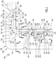
- the only requirement is that the connecting channels between separate media supply structures be lowered to the base level (e.g., the block area of the bipolar plate) in order to create a fluid-tight seal, for example, through a weld seam, in this intermediate area between two connecting channels, thus separating the fluid media conveyed in the two connecting channels from each other.
- the fluid medium guided in the medium channel, the connecting channel and the flow field can in particular be a fuel gas, an oxidizing agent or a coolant.
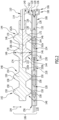
- the flow field-side mouth opening of the connecting channel has a larger fluid passage area than the medium channel-side mouth opening of the connecting channel.
- the flow field-side opening of the connecting channel opens at a corner region of the flow field.
- the connecting channel is arranged at a corner region of the active surface of the membrane electrode assembly of an electrochemical unit
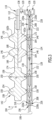
- the present invention is particularly advantageous because, without an offset between at least one flow field-side edge of the flow field-side opening of the connecting channel and at least one medium channel-side edge of the medium channel-side mouth opening of the connecting channel, the flow field-side mouth opening would have a significantly smaller fluid passage area than the medium channel-side mouth opening of the connecting channel.
- the connecting channel can be widened on two sides (on the flow field side and on the medium channel side) or only on one side (on the medium channel side or, preferably, on the flow field side) or only have an offset between the flow field side orifice opening and the medium channel side orifice opening along the circumferential direction of the flow field.
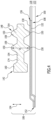
- the first flow field-side edge of the flow field-side mouth opening of the connecting channel is preferably at a smaller distance from the first medium channel-side edge of the medium channel-side mouth opening of the connecting channel than from the second medium channel-side edge of the medium channel-side mouth opening.
- the second flow field-side edge of the flow field-side mouth opening of the connecting channel is preferably at a smaller distance from the second medium channel-side edge of the medium channel-side mouth opening of the connecting channel than from the first medium channel-side edge of the medium channel-side mouth opening.
- the first medium channel-side edge of the medium channel-side orifice is connected to the first flow field-side edge of the flow field-side orifice by a first edge line, which forms a first lateral boundary of the connecting channel
- the second medium channel-side edge of the medium channel-side orifice is connected to the second flow field-side edge of the flow field-side orifice by a second edge line, which forms a second lateral boundary of the connecting channel.
- the invention provides that the first edge line and/or the second edge line is stepped.
Landscapes
- Chemical & Material Sciences (AREA)
- Life Sciences & Earth Sciences (AREA)
- Engineering & Computer Science (AREA)
- Manufacturing & Machinery (AREA)
- Sustainable Development (AREA)
- Sustainable Energy (AREA)
- Chemical Kinetics & Catalysis (AREA)
- Electrochemistry (AREA)
- General Chemical & Material Sciences (AREA)
- Composite Materials (AREA)
- Fuel Cell (AREA)
- Electrolytic Production Of Non-Metals, Compounds, Apparatuses Therefor (AREA)
Applications Claiming Priority (3)
| Application Number | Priority Date | Filing Date | Title |
|---|---|---|---|
| DE102018104172.1A DE102018104172A1 (de) | 2018-02-23 | 2018-02-23 | Elektrochemische Vorrichtung |
| EP19705305.1A EP3756231B1 (fr) | 2018-02-23 | 2019-02-08 | Structure de distribution de fluide pour dispositif électrochimique |
| PCT/EP2019/053112 WO2019162106A1 (fr) | 2018-02-23 | 2019-02-08 | Structure d'alimentation en milieu pour dispositif électrochimique |
Related Parent Applications (2)
| Application Number | Title | Priority Date | Filing Date |
|---|---|---|---|
| EP19705305.1A Division EP3756231B1 (fr) | 2018-02-23 | 2019-02-08 | Structure de distribution de fluide pour dispositif électrochimique |
| EP19705305.1A Division-Into EP3756231B1 (fr) | 2018-02-23 | 2019-02-08 | Structure de distribution de fluide pour dispositif électrochimique |
Publications (2)
| Publication Number | Publication Date |
|---|---|
| EP4576281A2 true EP4576281A2 (fr) | 2025-06-25 |
| EP4576281A3 EP4576281A3 (fr) | 2025-09-03 |
Family
ID=65433646
Family Applications (2)
| Application Number | Title | Priority Date | Filing Date |
|---|---|---|---|
| EP25176178.9A Pending EP4576281A3 (fr) | 2018-02-23 | 2019-02-08 | Structure d'alimentation en milieu pour dispositif électrochimique |
| EP19705305.1A Active EP3756231B1 (fr) | 2018-02-23 | 2019-02-08 | Structure de distribution de fluide pour dispositif électrochimique |
Family Applications After (1)
| Application Number | Title | Priority Date | Filing Date |
|---|---|---|---|
| EP19705305.1A Active EP3756231B1 (fr) | 2018-02-23 | 2019-02-08 | Structure de distribution de fluide pour dispositif électrochimique |
Country Status (5)
| Country | Link |
|---|---|
| US (1) | US12057607B2 (fr) |
| EP (2) | EP4576281A3 (fr) |
| CN (1) | CN111727523A (fr) |
| DE (1) | DE102018104172A1 (fr) |
| WO (1) | WO2019162106A1 (fr) |
Families Citing this family (2)
| Publication number | Priority date | Publication date | Assignee | Title |
|---|---|---|---|---|
| DE102022126790A1 (de) * | 2022-10-13 | 2024-04-18 | Ekpo Fuel Cell Technologies Gmbh | Elektrochemische Vorrichtung |
| DE102023207321A1 (de) * | 2023-08-01 | 2025-02-06 | Robert Bosch Gesellschaft mit beschränkter Haftung | Elektrolysezellensystem |
Citations (3)
| Publication number | Priority date | Publication date | Assignee | Title |
|---|---|---|---|---|
| DE102014104017A1 (de) | 2014-03-24 | 2015-09-24 | Elringklinger Ag | Elektrochemische Vorrichtung |
| US20160118673A1 (en) | 2013-06-06 | 2016-04-28 | Volkswagen Ag | Bipolar plate, fuel cell having such a plate and motor vehicle having such a fuel cell |
| DE202015104972U1 (de) | 2015-09-18 | 2016-12-20 | Reinz-Dichtungs-Gmbh | Separatorplatte für ein elektrochemisches System |
Family Cites Families (1)
| Publication number | Priority date | Publication date | Assignee | Title |
|---|---|---|---|---|
| DE10323646B4 (de) * | 2003-05-26 | 2012-09-20 | Daimler Ag | Bipolarplatte für eine Brennstoffzellenanordnung |
-
2018
- 2018-02-23 DE DE102018104172.1A patent/DE102018104172A1/de active Pending
-
2019
- 2019-02-08 EP EP25176178.9A patent/EP4576281A3/fr active Pending
- 2019-02-08 WO PCT/EP2019/053112 patent/WO2019162106A1/fr not_active Ceased
- 2019-02-08 CN CN201980013753.7A patent/CN111727523A/zh active Pending
- 2019-02-08 EP EP19705305.1A patent/EP3756231B1/fr active Active
-
2020
- 2020-08-21 US US16/999,203 patent/US12057607B2/en active Active
Patent Citations (3)
| Publication number | Priority date | Publication date | Assignee | Title |
|---|---|---|---|---|
| US20160118673A1 (en) | 2013-06-06 | 2016-04-28 | Volkswagen Ag | Bipolar plate, fuel cell having such a plate and motor vehicle having such a fuel cell |
| DE102014104017A1 (de) | 2014-03-24 | 2015-09-24 | Elringklinger Ag | Elektrochemische Vorrichtung |
| DE202015104972U1 (de) | 2015-09-18 | 2016-12-20 | Reinz-Dichtungs-Gmbh | Separatorplatte für ein elektrochemisches System |
Also Published As
| Publication number | Publication date |
|---|---|
| DE102018104172A1 (de) | 2019-08-29 |
| EP3756231A1 (fr) | 2020-12-30 |
| EP4576281A3 (fr) | 2025-09-03 |
| US20200381748A1 (en) | 2020-12-03 |
| WO2019162106A1 (fr) | 2019-08-29 |
| US12057607B2 (en) | 2024-08-06 |
| EP3756231B1 (fr) | 2025-06-25 |
| CN111727523A (zh) | 2020-09-29 |
Similar Documents
| Publication | Publication Date | Title |
|---|---|---|
| DE102005057045B4 (de) | Bipolarplatte und deren Verwendung in einer Brennstoffzelleneinheit | |
| WO2018220065A1 (fr) | Plaque de séparation pour un système électrochimique | |
| EP3577708B1 (fr) | Plaque bipolaire ayant distribution de gaz améliorée pour pile à combustible | |
| DE202018103058U1 (de) | Separatorplatte für ein elektrochemisches System | |
| EP4566105A2 (fr) | Plaque bipolaire destinée à une unité électrochimique d'un dispositif électrochimique et dispositif électrochimique | |
| DE102022119209A1 (de) | Bipolarplatte für eine elektrochemische Einheit einer elektrochemischen Vorrichtung und elektrochemische Vorrichtung | |
| EP3756231B1 (fr) | Structure de distribution de fluide pour dispositif électrochimique | |
| DE3516766A1 (de) | Brennstoffzelle | |
| DE102022122717B3 (de) | Bipolarplatte und elektrochemische Zelle | |
| DE102021134038A1 (de) | Verfahren zur Herstellung einer Bipolarplattenlage für eine Bipolarplatte einer elektrochemischen Einheit, Bipolarplattenlage für eine Bipolarplatte einer elektrochemischen Einheit und elektrochemische Einheit für eine elektrochemische Vorrichtung | |
| DE102024122752A1 (de) | Bipolarplatte mit mindestens einer Lage und mindestens einem Einlegeteil | |
| DE102005057044B4 (de) | Bipolarplatte und deren Verwendung | |
| EP4128401B1 (fr) | Plaque bipolaire pour un dispositif électrochimique | |
| DE10323646A1 (de) | Bipolarplatte für eine Brennstoffzellenanordnung | |
| DE102022203540A1 (de) | Separatorplatte mit homogenisierter sickenkraft im portbereich | |
| DE102022208625A1 (de) | Separatorplatte und elektrochemische Zelle | |
| DE102006039794A1 (de) | Polymer-Feststoffbrennstoffzelle | |
| DE102023207321A1 (de) | Elektrolysezellensystem | |
| EP4566104A1 (fr) | Plaque bipolaire pour unité électrochimique d'appareil électrochimique, et appareil électrochimique | |
| DE102023104689A1 (de) | Bipolarplatte für eine elektrochemische Einheit einer elektrochemischen Vorrichtung und elektrochemische Vorrichtung | |
| DE102024114370A1 (de) | Bipolarplatte und Brennstoffzellenvorrichtung mit einer Bipolarplatte | |
| EP4293761A1 (fr) | Guidage de l'écoulement de fluide pour le guidage d'un fluide en écoulement et utilisations du guidage de l'écoulement de fluide | |
| DE202023107632U1 (de) | Separatorplatte für ein elektrochemisches System und elektrochemisches System | |
| WO2024256509A1 (fr) | Plaque séparatrice pour système électrochimique | |
| DE102022113249A1 (de) | Elektrochemische Vorrichtung |
Legal Events
| Date | Code | Title | Description |
|---|---|---|---|
| PUAI | Public reference made under article 153(3) epc to a published international application that has entered the european phase |
Free format text: ORIGINAL CODE: 0009012 |
|
| STAA | Information on the status of an ep patent application or granted ep patent |
Free format text: STATUS: THE APPLICATION HAS BEEN PUBLISHED |
|
| AC | Divisional application: reference to earlier application |
Ref document number: 3756231 Country of ref document: EP Kind code of ref document: P |
|
| AK | Designated contracting states |
Kind code of ref document: A2 Designated state(s): AL AT BE BG CH CY CZ DE DK EE ES FI FR GB GR HR HU IE IS IT LI LT LU LV MC MK MT NL NO PL PT RO RS SE SI SK SM TR |
|
| PUAL | Search report despatched |
Free format text: ORIGINAL CODE: 0009013 |
|
| P01 | Opt-out of the competence of the unified patent court (upc) registered |
Free format text: CASE NUMBER: APP_31178/2025 Effective date: 20250627 |
|
| AK | Designated contracting states |
Kind code of ref document: A3 Designated state(s): AL AT BE BG CH CY CZ DE DK EE ES FI FR GB GR HR HU IE IS IT LI LT LU LV MC MK MT NL NO PL PT RO RS SE SI SK SM TR |
|
| RIC1 | Information provided on ipc code assigned before grant |
Ipc: H01M 8/0273 20160101AFI20250730BHEP Ipc: H01M 8/0206 20160101ALI20250730BHEP Ipc: H01M 8/0228 20160101ALI20250730BHEP Ipc: H01M 8/0258 20160101ALI20250730BHEP Ipc: H01M 8/0267 20160101ALI20250730BHEP Ipc: H01M 8/2483 20160101ALI20250730BHEP |
|
| STAA | Information on the status of an ep patent application or granted ep patent |
Free format text: STATUS: REQUEST FOR EXAMINATION WAS MADE |