EP4576435A1 - Connecteur à déplacement d'isolant - Google Patents
Connecteur à déplacement d'isolant Download PDFInfo
- Publication number
- EP4576435A1 EP4576435A1 EP24213620.8A EP24213620A EP4576435A1 EP 4576435 A1 EP4576435 A1 EP 4576435A1 EP 24213620 A EP24213620 A EP 24213620A EP 4576435 A1 EP4576435 A1 EP 4576435A1
- Authority
- EP
- European Patent Office
- Prior art keywords
- insulation displacement
- contact
- wire
- pair
- pieces
- Prior art date
- Legal status (The legal status is an assumption and is not a legal conclusion. Google has not performed a legal analysis and makes no representation as to the accuracy of the status listed.)
- Granted
Links
Images



Classifications
-
- H—ELECTRICITY
- H01—ELECTRIC ELEMENTS
- H01R—ELECTRICALLY-CONDUCTIVE CONNECTIONS; STRUCTURAL ASSOCIATIONS OF A PLURALITY OF MUTUALLY-INSULATED ELECTRICAL CONNECTING ELEMENTS; COUPLING DEVICES; CURRENT COLLECTORS
- H01R4/00—Electrically-conductive connections between two or more conductive members in direct contact, i.e. touching one another; Means for effecting or maintaining such contact; Electrically-conductive connections having two or more spaced connecting locations for conductors and using contact members penetrating insulation
- H01R4/24—Connections using contact members penetrating or cutting insulation or cable strands
- H01R4/2416—Connections using contact members penetrating or cutting insulation or cable strands the contact members having insulation-cutting edges, e.g. of tuning fork type
- H01R4/242—Connections using contact members penetrating or cutting insulation or cable strands the contact members having insulation-cutting edges, e.g. of tuning fork type the contact members being plates having a single slot
- H01R4/2425—Flat plates, e.g. multi-layered flat plates
- H01R4/2429—Flat plates, e.g. multi-layered flat plates mounted in an insulating base
- H01R4/2433—Flat plates, e.g. multi-layered flat plates mounted in an insulating base one part of the base being movable to push the cable into the slot
-
- H—ELECTRICITY
- H01—ELECTRIC ELEMENTS
- H01R—ELECTRICALLY-CONDUCTIVE CONNECTIONS; STRUCTURAL ASSOCIATIONS OF A PLURALITY OF MUTUALLY-INSULATED ELECTRICAL CONNECTING ELEMENTS; COUPLING DEVICES; CURRENT COLLECTORS
- H01R4/00—Electrically-conductive connections between two or more conductive members in direct contact, i.e. touching one another; Means for effecting or maintaining such contact; Electrically-conductive connections having two or more spaced connecting locations for conductors and using contact members penetrating insulation
- H01R4/24—Connections using contact members penetrating or cutting insulation or cable strands
- H01R4/2416—Connections using contact members penetrating or cutting insulation or cable strands the contact members having insulation-cutting edges, e.g. of tuning fork type
- H01R4/242—Connections using contact members penetrating or cutting insulation or cable strands the contact members having insulation-cutting edges, e.g. of tuning fork type the contact members being plates having a single slot
- H01R4/2425—Flat plates, e.g. multi-layered flat plates
-
- H—ELECTRICITY
- H01—ELECTRIC ELEMENTS
- H01R—ELECTRICALLY-CONDUCTIVE CONNECTIONS; STRUCTURAL ASSOCIATIONS OF A PLURALITY OF MUTUALLY-INSULATED ELECTRICAL CONNECTING ELEMENTS; COUPLING DEVICES; CURRENT COLLECTORS
- H01R4/00—Electrically-conductive connections between two or more conductive members in direct contact, i.e. touching one another; Means for effecting or maintaining such contact; Electrically-conductive connections having two or more spaced connecting locations for conductors and using contact members penetrating insulation
- H01R4/24—Connections using contact members penetrating or cutting insulation or cable strands
- H01R4/2404—Connections using contact members penetrating or cutting insulation or cable strands the contact members having teeth, prongs, pins or needles penetrating the insulation
-
- H—ELECTRICITY
- H01—ELECTRIC ELEMENTS
- H01R—ELECTRICALLY-CONDUCTIVE CONNECTIONS; STRUCTURAL ASSOCIATIONS OF A PLURALITY OF MUTUALLY-INSULATED ELECTRICAL CONNECTING ELEMENTS; COUPLING DEVICES; CURRENT COLLECTORS
- H01R13/00—Details of coupling devices of the kinds covered by groups H01R12/70 or H01R24/00 - H01R33/00
- H01R13/58—Means for relieving strain on wire connection, e.g. cord grip, for avoiding loosening of connections between wires and terminals within a coupling device terminating a cable
-
- H—ELECTRICITY
- H01—ELECTRIC ELEMENTS
- H01R—ELECTRICALLY-CONDUCTIVE CONNECTIONS; STRUCTURAL ASSOCIATIONS OF A PLURALITY OF MUTUALLY-INSULATED ELECTRICAL CONNECTING ELEMENTS; COUPLING DEVICES; CURRENT COLLECTORS
- H01R13/00—Details of coupling devices of the kinds covered by groups H01R12/70 or H01R24/00 - H01R33/00
- H01R13/62—Means for facilitating engagement or disengagement of coupling parts or for holding them in engagement
-
- H—ELECTRICITY
- H01—ELECTRIC ELEMENTS
- H01R—ELECTRICALLY-CONDUCTIVE CONNECTIONS; STRUCTURAL ASSOCIATIONS OF A PLURALITY OF MUTUALLY-INSULATED ELECTRICAL CONNECTING ELEMENTS; COUPLING DEVICES; CURRENT COLLECTORS
- H01R4/00—Electrically-conductive connections between two or more conductive members in direct contact, i.e. touching one another; Means for effecting or maintaining such contact; Electrically-conductive connections having two or more spaced connecting locations for conductors and using contact members penetrating insulation
- H01R4/24—Connections using contact members penetrating or cutting insulation or cable strands
- H01R4/2416—Connections using contact members penetrating or cutting insulation or cable strands the contact members having insulation-cutting edges, e.g. of tuning fork type
- H01R4/2445—Connections using contact members penetrating or cutting insulation or cable strands the contact members having insulation-cutting edges, e.g. of tuning fork type the contact members having additional means acting on the insulation or the wire, e.g. additional insulation penetrating means, strain relief means or wire cutting knives
-
- H—ELECTRICITY
- H01—ELECTRIC ELEMENTS
- H01R—ELECTRICALLY-CONDUCTIVE CONNECTIONS; STRUCTURAL ASSOCIATIONS OF A PLURALITY OF MUTUALLY-INSULATED ELECTRICAL CONNECTING ELEMENTS; COUPLING DEVICES; CURRENT COLLECTORS
- H01R4/00—Electrically-conductive connections between two or more conductive members in direct contact, i.e. touching one another; Means for effecting or maintaining such contact; Electrically-conductive connections having two or more spaced connecting locations for conductors and using contact members penetrating insulation
- H01R4/24—Connections using contact members penetrating or cutting insulation or cable strands
- H01R4/2416—Connections using contact members penetrating or cutting insulation or cable strands the contact members having insulation-cutting edges, e.g. of tuning fork type
- H01R4/2445—Connections using contact members penetrating or cutting insulation or cable strands the contact members having insulation-cutting edges, e.g. of tuning fork type the contact members having additional means acting on the insulation or the wire, e.g. additional insulation penetrating means, strain relief means or wire cutting knives
- H01R4/245—Connections using contact members penetrating or cutting insulation or cable strands the contact members having insulation-cutting edges, e.g. of tuning fork type the contact members having additional means acting on the insulation or the wire, e.g. additional insulation penetrating means, strain relief means or wire cutting knives the additional means having two or more slotted flat portions
Definitions
- the present disclosure relates to an insulation displacement connector.
- Patent Literature 1 Japanese Unexamined Patent Application Publication No. 2011-29125 discloses an insulation displacement connector 104 that includes an insulation displacement contact (IDC) 102 where a wire 101 is press-fit between a pair of IDC blades 100 and a compressing member 103 in a cylindrical shape that pushes the pair of IDC blades 100 so that the pair of IDC blades 100 come closer to each other.
- IDC insulation displacement contact
- the wire 101 is press-fit into a slot 106 between the pair of IDC blades 100.
- a covering 107 of the wire 101 is thereby cut by the pair of the pair of IDC blades 100.
- This cutting causes a core wire 108 of the wire 101 to be exposed, and the exposed core wire 108 comes into contact with the pair of IDC blades 100.
- the pair of IDC blades 100 are pushed by the compressing member 103 so as to come closer to each other and thereby the slot 106 is narrowed, and consequently an oxide layer formed on the core wire 108 of the wire 101 is removed.
- Patent Literature 1 room for improvement remains in terms of contact reliability.
- An object of the present disclosure is to provide an insulation displacement connector with high contact reliability.
- an insulation displacement connector including an insulation displacement contact including a base and a pair of insulation displacement pieces extending from the base, where a wire is press-fit into a slot formed between the pair of insulation displacement pieces and thereby a core wire of the wire comes into contact with the pair of insulation displacement pieces, and a twisting member configured to mate with the insulation displacement contact and thereby twist the wire so that a longitudinal direction of the core wire of the wire changes when viewed along a press-fit direction of press-fitting the wire into the slot of the insulation displacement contact.
- an insulation displacement connector with high contact reliability is achieved.
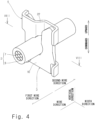
- the twisting member 5 is formed in S shape when viewed from above.
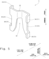
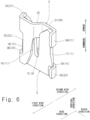
- the twisting member 5 includes a pair of covering contact pieces 20, a pair of pushing parts 21, a coupling part 22, and a pair of member-side lock parts 23.
- the first member-side lock part 38 is opposed to the first contact-side lock part 18 in the vertical direction, and it is located down below the first contact-side lock part 18.
- the second member-side lock part 39 is opposed to the second contact-side lock part 19 in the vertical direction, and it is located down below the second contact-side lock part 19. This restricts the twisting member 5 from moving upward relative to the insulation displacement contact 3 in the state where the twisting member 5 mates with the insulation displacement contact 3, so that mating of the twisting member 5 and the insulation displacement contact 3 is locked.
- the first member-side lock part 38 comes into contact with the first contact-side lock part 18 and thereby the first member-side lock part 38 is elastically displaced outward in the width direction as the first covering contact piece 30 is twisted and deformed, and after the first member-side lock part 38 climbs over the first contact-side lock part 18, the first member-side lock part 38 is elastically restored inward in the width direction by the elastic restoring force of the first covering contact piece 30. Consequently, the first contact-side lock part 18 and the first member-side lock part 38 are aligned in this recited order from top to bottom, and the first contact-side lock part 18 and the first member-side lock part 38 are opposed to each other in the vertical direction.
- Mating the twisting member 5 with the insulation displacement contact 3 means establishing the above-described positional relation of the first contact-side lock part 18, the second contact-side lock part 19, the first member-side lock part 38, and the second member-side lock part 39. This positional relation restricts the twisting member 5 from moving upward relative to the insulation displacement contact 3, so that mating of the insulation displacement contact 3 and the twisting member 5 is locked.
- the pair of IDC pieces 11 come into contact with the pair of pushing parts 21, respectively, in the width direction, and thereby an inward force in the width direction acts on the pair of IDC pieces 11.
- This increases the contact pressure of the core wire 7 of the wire 2 on the pair of IDC pieces 11, which improves the contact reliability between the core wire 7 of the wire 2 and the insulation displacement contact 3.
- the pair of pushing parts 21 are slightly elastically displaced outward in the width direction with elastic displacement of the pair of covering contact pieces 20 and the coupling part 22, thereby absorbing a certain degree of dimensional error during manufacture. This prevents an excessive inward force in the width direction from acting on the pair of IDC pieces 11 when the pair of IDC pieces 11 come into contact with the pair of pushing parts 21, respectively, in the width direction, which protects the core wire 7 from damage.
- the first covering contact piece 30 and the second covering contact piece 31 are pushed inward in the width direction against the covering 8 of the wire 2.
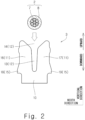
- the first covering contact piece 30 and the second covering contact piece 31 are disposed on opposite sides to each other with the insulation displacement contact 3 interposed therebetween and also disposed on opposite sides to each other with the wire 2 interposed therebetween when viewed from above in Fig. 9 .
- a couple acts on the wire 2. Consequently, the wire 2 is twisted locally counter-clockwise in a proximity area P of the wire press-fit slot 12 of the insulation displacement contact 3.
- the longitudinal direction of the wire 2 in the proximity area P is shown by a line segment Q.
- the line segment Q is inclined counter-clockwise relative to the wire direction when viewed from above. This inclination locally significantly increases the contact pressure of the core wire 7 of the wire 2 on the first IDC piece 16. Likewise, this inclination locally significantly increases the contact pressure of the core wire 7 of the wire 2 on the second IDC piece 17. As a result, the maximum value of the contact pressure of the core wire 7 of the wire 2 on the insulation displacement contact 3 is higher than that before mating, which achieves high contact reliability between the wire 2 and the insulation displacement contact 3.
- the problem that the contact pressure of the core wire 7 of the wire 2 on the pair of IDC pieces 11 decreases due to displacement of the pair of IDC pieces 11 outward in the width direction by stress relaxation is reduced by another approach.
- the second pushing part 34 is inclined relative to the wire direction when viewed from above.
- the second pushing part 34 projects in the first wire direction so as to come apart from the wire 2 when viewed from above.
- the second pushing part 34 slides over the second IDC piece 17 and is displaced in the second wire direction.
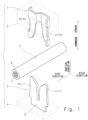
- the insulation displacement connector 1 includes the insulation displacement contact 3 and the twisting member 5.
- the insulation displacement contact 3 includes the base 10 and the pair of IDC pieces 11 extending from the base 10.
- the wire 2 is press-fit into the wire press-fit slot 12 (slot) formed between the pair of IDC pieces 11, and thereby the core wire 7 of the wire 2 comes into contact with the pair of IDC pieces 11.
- Fig. 1 the insulation displacement connector 1 includes the insulation displacement contact 3 and the twisting member 5.
- the insulation displacement contact 3 includes the base 10 and the pair of IDC pieces 11 extending from the base 10.
- the wire 2 is press-fit into the wire press-fit slot 12 (slot) formed between the pair of IDC pieces 11, and thereby the core wire 7 of the wire 2 comes into contact with the pair of IDC pieces 11.
- twisting member 5 further includes the coupling part 22 that couples the pair of covering contact pieces 20 and is inserted into the wire press-fit slot 12 of the insulation displacement contact 3. This structure prevents the wire 2 from being pulled upward out of the wire press-fit slot 12.
- the twisting member 5 includes the pair of pushing parts 21 that push the pair of IDC pieces 11, respectively, so that the pair of IDC pieces 11 come closer to each other. This structure further increases the contact pressure of the core wire 7 of the wire 2 on the pair of IDC pieces 11.
- the pair of pushing parts 21 are formed to project from the pair of covering contact pieces 20, respectively. This structure allows the pair of pushing parts 21 to come apart from each other with elastic deformation of the pair of covering contact pieces 20, which prevents an excessive increase in the contact pressure of the core wire 7 of the wire 2 on the pair of IDC pieces 11.
- the pair of pushing parts 21 project to be apart from the wire 2.
- the pair of IDC pieces 11 come apart from each other by stress relaxation
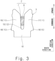
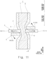
- the pair of pushing parts 21 slide over the pair of IDC pieces 11, respectively, and the pair of covering contact pieces 20 rotate about the coupling part 22 so as to be apart from the pair of IDC pieces 11 when viewed from above shown in Fig. 11 .
- This rotation increases a couple that is generated when the pair of covering contact pieces 20 come into contact with the covering 8 of the wire 2.
- the contact pressure of the core wire 7 of the wire 2 on the pair of IDC pieces 11 is maintained.
- the pair of pushing parts 21, the pair of covering contact pieces 20, and the coupling part 22 form an S-shape when viewed along the press-fit direction. This allows the twisting member 5 to be achieved in a simple structure.
- the first pushing part 33 which is one of the pair of pushing parts 21, the first covering contact piece 30, which is one of the pair of covering contact pieces 20, the coupling part 22, the second covering contact piece 31, which is the other one of the pair of covering contact pieces 20, and the second pushing part 34, which is the other one of the pair of pushing parts 21, are linked together in this recited order.
- the insulation displacement contact 3 includes the pair of contact-side lock parts 15.
- the twisting member 5 includes the pair of member-side lock parts 23. In the state where the twisting member 5 mates with the insulation displacement contact 3, the pair of contact-side lock parts 15 and the pair of member-side lock parts 23 are aligned in this recited order down below, which locks mating of the twisting member 5 and the insulation displacement contact 3. This structure allows the mating state of the twisting member 5 and the insulation displacement contact 3 to be maintained stably.
- the pair of covering contact pieces 20 may cut the covering 8 of the wire 2 and come into direct contact with the core wire 7 of the wire 2.
- one of the pair of contact-side lock parts 15 may be omitted.
- one of the pair of member-side lock parts 23 may be omitted. All of the pair of contact-side lock parts 15 and the pair of member-side lock parts 23 may be omitted.
- the twisting member 5 forms an S-shape when viewed from above in the above-described embodiment.
- the twisting member 5 may form an inverted S-shape when viewed from above.
- the wire 2 rotates clockwise when viewed from above.
- the insulation displacement connector 1 is a connector in which when the wire 2 is pushed into the insulation displacement contact 3 (IDC: Insulation Displacement Contact) without removing the covering 8 of the wire 2, the covering 8 of the wire 2 is locally cut and thereby the core wire 7 of the wire 2 becomes electrically continuous with the insulation displacement contact 3.
- the insulation displacement contact 3 is a terminal that is able to come into electrical contact with the core wire 7 of the wire 2 by locally cutting the covering 8 of the wire 2.
Landscapes
- Connections By Means Of Piercing Elements, Nuts, Or Screws (AREA)
- Coupling Device And Connection With Printed Circuit (AREA)
Applications Claiming Priority (1)
| Application Number | Priority Date | Filing Date | Title |
|---|---|---|---|
| JP2023212920A JP2025096923A (ja) | 2023-12-18 | 2023-12-18 | 圧接コネクタ |
Publications (2)
| Publication Number | Publication Date |
|---|---|
| EP4576435A1 true EP4576435A1 (fr) | 2025-06-25 |
| EP4576435B1 EP4576435B1 (fr) | 2025-12-31 |
Family
ID=93562430
Family Applications (1)
| Application Number | Title | Priority Date | Filing Date |
|---|---|---|---|
| EP24213620.8A Active EP4576435B1 (fr) | 2023-12-18 | 2024-11-18 | Connecteur à déplacement d'isolant |
Country Status (4)
| Country | Link |
|---|---|
| US (1) | US20250202135A1 (fr) |
| EP (1) | EP4576435B1 (fr) |
| JP (1) | JP2025096923A (fr) |
| CN (1) | CN120184619A (fr) |
Citations (4)
| Publication number | Priority date | Publication date | Assignee | Title |
|---|---|---|---|---|
| US3824527A (en) * | 1972-08-03 | 1974-07-16 | Amp Inc | Wire-in-slot electrical connections |
| US4089580A (en) * | 1977-02-25 | 1978-05-16 | Amp Incorporated | Multi-contact connector and contact terminal for flat cable having a plurality of conductors on close center lines |
| EP0014081A1 (fr) * | 1979-01-24 | 1980-08-06 | The Post Office | Borne électrique |
| JP2011029125A (ja) | 2009-07-29 | 2011-02-10 | Sumitomo Wiring Syst Ltd | 圧接コネクタ |
-
2023
- 2023-12-18 JP JP2023212920A patent/JP2025096923A/ja active Pending
-
2024
- 2024-10-08 CN CN202411392904.3A patent/CN120184619A/zh active Pending
- 2024-10-24 US US18/925,736 patent/US20250202135A1/en active Pending
- 2024-11-18 EP EP24213620.8A patent/EP4576435B1/fr active Active
Patent Citations (4)
| Publication number | Priority date | Publication date | Assignee | Title |
|---|---|---|---|---|
| US3824527A (en) * | 1972-08-03 | 1974-07-16 | Amp Inc | Wire-in-slot electrical connections |
| US4089580A (en) * | 1977-02-25 | 1978-05-16 | Amp Incorporated | Multi-contact connector and contact terminal for flat cable having a plurality of conductors on close center lines |
| EP0014081A1 (fr) * | 1979-01-24 | 1980-08-06 | The Post Office | Borne électrique |
| JP2011029125A (ja) | 2009-07-29 | 2011-02-10 | Sumitomo Wiring Syst Ltd | 圧接コネクタ |
Also Published As
| Publication number | Publication date |
|---|---|
| JP2025096923A (ja) | 2025-06-30 |
| EP4576435B1 (fr) | 2025-12-31 |
| CN120184619A (zh) | 2025-06-20 |
| US20250202135A1 (en) | 2025-06-19 |
Similar Documents
| Publication | Publication Date | Title |
|---|---|---|
| US5498173A (en) | Electrical connecting device | |
| US8251758B2 (en) | Electrical contact | |
| US3954320A (en) | Electrical connecting devices for terminating cords | |
| CN101183752B (zh) | 具有闩锁偏置构件的插口连接器 | |
| US11075479B2 (en) | Terminal fitting | |
| US9472875B2 (en) | Wire-to-board connector | |
| US20170271784A1 (en) | Electrical Connection Device, A Method of Manufacturing an Electrical Cable and A Manufactured Electrical Coaxial Cable | |
| KR0139698B1 (ko) | 전기 커넥터와, 블레이드 접촉부와 결합시키기 위한 단자 | |
| CN1192297A (zh) | 电气端子 | |
| JP2011134582A (ja) | 平型ケーブル用コネクタ、その製造方法及びロック機構 | |
| US12334660B2 (en) | Electrical terminal for flat flexible cables | |
| US7255611B2 (en) | Connector | |
| EP3691047A1 (fr) | Structure de connecteur | |
| JP4632454B2 (ja) | ケーブルコネクタ | |
| EP4576435B1 (fr) | Connecteur à déplacement d'isolant | |
| EP3667822B1 (fr) | Système de connexion de terminal par douille de sertissage pour connecteurs électriques | |
| CN113889774A (zh) | 用于扁平柔性电缆的电气端子 | |
| US12362503B2 (en) | Terminal which makes direct wire-to-wire or wire-to-mating surface connection | |
| CN113889776B (zh) | 用于扁平柔性电缆的电气端子 | |
| JP2000294335A (ja) | コネクタの係止構造 | |
| US12562507B1 (en) | Direct wire terminal assembly | |
| CN1218337C (zh) | 微型开关及其制造方法 | |
| US20250038431A1 (en) | Terminal having an insulation displacement contact | |
| CN217983905U (zh) | 后缘解锁连接器 | |
| JP7330051B2 (ja) | コネクタ及びワイヤーハーネス |
Legal Events
| Date | Code | Title | Description |
|---|---|---|---|
| PUAI | Public reference made under article 153(3) epc to a published international application that has entered the european phase |
Free format text: ORIGINAL CODE: 0009012 |
|
| STAA | Information on the status of an ep patent application or granted ep patent |
Free format text: STATUS: REQUEST FOR EXAMINATION WAS MADE |
|
| STAA | Information on the status of an ep patent application or granted ep patent |
Free format text: STATUS: EXAMINATION IS IN PROGRESS |
|
| 17P | Request for examination filed |
Effective date: 20241118 |
|
| AK | Designated contracting states |
Kind code of ref document: A1 Designated state(s): AL AT BE BG CH CY CZ DE DK EE ES FI FR GB GR HR HU IE IS IT LI LT LU LV MC ME MK MT NL NO PL PT RO RS SE SI SK SM TR |
|
| 17Q | First examination report despatched |
Effective date: 20250612 |
|
| GRAP | Despatch of communication of intention to grant a patent |
Free format text: ORIGINAL CODE: EPIDOSNIGR1 |
|
| STAA | Information on the status of an ep patent application or granted ep patent |
Free format text: STATUS: GRANT OF PATENT IS INTENDED |
|
| INTG | Intention to grant announced |
Effective date: 20251027 |
|
| GRAS | Grant fee paid |
Free format text: ORIGINAL CODE: EPIDOSNIGR3 |
|
| GRAA | (expected) grant |
Free format text: ORIGINAL CODE: 0009210 |
|
| STAA | Information on the status of an ep patent application or granted ep patent |
Free format text: STATUS: THE PATENT HAS BEEN GRANTED |
|
| AK | Designated contracting states |
Kind code of ref document: B1 Designated state(s): AL AT BE BG CH CY CZ DE DK EE ES FI FR GB GR HR HU IE IS IT LI LT LU LV MC ME MK MT NL NO PL PT RO RS SE SI SK SM TR |
|
| REG | Reference to a national code |
Ref country code: CH Ref legal event code: F10 Free format text: ST27 STATUS EVENT CODE: U-0-0-F10-F00 (AS PROVIDED BY THE NATIONAL OFFICE) Effective date: 20251231 Ref country code: GB Ref legal event code: FG4D |
|
| REG | Reference to a national code |
Ref country code: DE Ref legal event code: R096 Ref document number: 602024001945 Country of ref document: DE |
|
| REG | Reference to a national code |
Ref country code: IE Ref legal event code: FG4D |
|
| REG | Reference to a national code |
Ref country code: LT Ref legal event code: MG9D |
|
| PG25 | Lapsed in a contracting state [announced via postgrant information from national office to epo] |
Ref country code: NO Free format text: LAPSE BECAUSE OF FAILURE TO SUBMIT A TRANSLATION OF THE DESCRIPTION OR TO PAY THE FEE WITHIN THE PRESCRIBED TIME-LIMIT Effective date: 20260331 |
|
| PG25 | Lapsed in a contracting state [announced via postgrant information from national office to epo] |
Ref country code: FI Free format text: LAPSE BECAUSE OF FAILURE TO SUBMIT A TRANSLATION OF THE DESCRIPTION OR TO PAY THE FEE WITHIN THE PRESCRIBED TIME-LIMIT Effective date: 20251231 Ref country code: HR Free format text: LAPSE BECAUSE OF FAILURE TO SUBMIT A TRANSLATION OF THE DESCRIPTION OR TO PAY THE FEE WITHIN THE PRESCRIBED TIME-LIMIT Effective date: 20251231 |
|
| PG25 | Lapsed in a contracting state [announced via postgrant information from national office to epo] |
Ref country code: RS Free format text: LAPSE BECAUSE OF FAILURE TO SUBMIT A TRANSLATION OF THE DESCRIPTION OR TO PAY THE FEE WITHIN THE PRESCRIBED TIME-LIMIT Effective date: 20260331 |
|
| PG25 | Lapsed in a contracting state [announced via postgrant information from national office to epo] |
Ref country code: LV Free format text: LAPSE BECAUSE OF FAILURE TO SUBMIT A TRANSLATION OF THE DESCRIPTION OR TO PAY THE FEE WITHIN THE PRESCRIBED TIME-LIMIT Effective date: 20251231 |
|
| PG25 | Lapsed in a contracting state [announced via postgrant information from national office to epo] |
Ref country code: BG Free format text: LAPSE BECAUSE OF FAILURE TO SUBMIT A TRANSLATION OF THE DESCRIPTION OR TO PAY THE FEE WITHIN THE PRESCRIBED TIME-LIMIT Effective date: 20251231 |
|
| REG | Reference to a national code |
Ref country code: NL Ref legal event code: MP Effective date: 20251231 |
|
| REG | Reference to a national code |
Ref country code: AT Ref legal event code: MK05 Ref document number: 1874524 Country of ref document: AT Kind code of ref document: T Effective date: 20251231 |
|
| PG25 | Lapsed in a contracting state [announced via postgrant information from national office to epo] |
Ref country code: NL Free format text: LAPSE BECAUSE OF FAILURE TO SUBMIT A TRANSLATION OF THE DESCRIPTION OR TO PAY THE FEE WITHIN THE PRESCRIBED TIME-LIMIT Effective date: 20251231 |
|
| PG25 | Lapsed in a contracting state [announced via postgrant information from national office to epo] |
Ref country code: LT Free format text: LAPSE BECAUSE OF FAILURE TO SUBMIT A TRANSLATION OF THE DESCRIPTION OR TO PAY THE FEE WITHIN THE PRESCRIBED TIME-LIMIT Effective date: 20251231 |
|
| PG25 | Lapsed in a contracting state [announced via postgrant information from national office to epo] |
Ref country code: SM Free format text: LAPSE BECAUSE OF FAILURE TO SUBMIT A TRANSLATION OF THE DESCRIPTION OR TO PAY THE FEE WITHIN THE PRESCRIBED TIME-LIMIT Effective date: 20251231 |
|
| PG25 | Lapsed in a contracting state [announced via postgrant information from national office to epo] |
Ref country code: ES Free format text: LAPSE BECAUSE OF FAILURE TO SUBMIT A TRANSLATION OF THE DESCRIPTION OR TO PAY THE FEE WITHIN THE PRESCRIBED TIME-LIMIT Effective date: 20251231 |
|
| PG25 | Lapsed in a contracting state [announced via postgrant information from national office to epo] |
Ref country code: PL Free format text: LAPSE BECAUSE OF FAILURE TO SUBMIT A TRANSLATION OF THE DESCRIPTION OR TO PAY THE FEE WITHIN THE PRESCRIBED TIME-LIMIT Effective date: 20251231 |
|
| PG25 | Lapsed in a contracting state [announced via postgrant information from national office to epo] |
Ref country code: IT Free format text: LAPSE BECAUSE OF FAILURE TO SUBMIT A TRANSLATION OF THE DESCRIPTION OR TO PAY THE FEE WITHIN THE PRESCRIBED TIME-LIMIT Effective date: 20251231 |
|
| PG25 | Lapsed in a contracting state [announced via postgrant information from national office to epo] |
Ref country code: AT Free format text: LAPSE BECAUSE OF FAILURE TO SUBMIT A TRANSLATION OF THE DESCRIPTION OR TO PAY THE FEE WITHIN THE PRESCRIBED TIME-LIMIT Effective date: 20251231 |
|
| PG25 | Lapsed in a contracting state [announced via postgrant information from national office to epo] |
Ref country code: EE Free format text: LAPSE BECAUSE OF FAILURE TO SUBMIT A TRANSLATION OF THE DESCRIPTION OR TO PAY THE FEE WITHIN THE PRESCRIBED TIME-LIMIT Effective date: 20251231 |
|
| PG25 | Lapsed in a contracting state [announced via postgrant information from national office to epo] |
Ref country code: IS Free format text: LAPSE BECAUSE OF FAILURE TO SUBMIT A TRANSLATION OF THE DESCRIPTION OR TO PAY THE FEE WITHIN THE PRESCRIBED TIME-LIMIT Effective date: 20260430 Ref country code: PT Free format text: LAPSE BECAUSE OF FAILURE TO SUBMIT A TRANSLATION OF THE DESCRIPTION OR TO PAY THE FEE WITHIN THE PRESCRIBED TIME-LIMIT Effective date: 20260430 |
|
| PG25 | Lapsed in a contracting state [announced via postgrant information from national office to epo] |
Ref country code: CZ Free format text: LAPSE BECAUSE OF FAILURE TO SUBMIT A TRANSLATION OF THE DESCRIPTION OR TO PAY THE FEE WITHIN THE PRESCRIBED TIME-LIMIT Effective date: 20251231 |
|
| PG25 | Lapsed in a contracting state [announced via postgrant information from national office to epo] |
Ref country code: SK Free format text: LAPSE BECAUSE OF FAILURE TO SUBMIT A TRANSLATION OF THE DESCRIPTION OR TO PAY THE FEE WITHIN THE PRESCRIBED TIME-LIMIT Effective date: 20251231 |
|
| PG25 | Lapsed in a contracting state [announced via postgrant information from national office to epo] |
Ref country code: SE Free format text: LAPSE BECAUSE OF FAILURE TO SUBMIT A TRANSLATION OF THE DESCRIPTION OR TO PAY THE FEE WITHIN THE PRESCRIBED TIME-LIMIT Effective date: 20251231 |