EP4576602A2 - Indication de faisceau commun basée sur une sélection de liaison - Google Patents
Indication de faisceau commun basée sur une sélection de liaison Download PDFInfo
- Publication number
- EP4576602A2 EP4576602A2 EP25175280.4A EP25175280A EP4576602A2 EP 4576602 A2 EP4576602 A2 EP 4576602A2 EP 25175280 A EP25175280 A EP 25175280A EP 4576602 A2 EP4576602 A2 EP 4576602A2
- Authority
- EP
- European Patent Office
- Prior art keywords
- wireless device
- tci
- base station
- mac
- coreset
- Prior art date
- Legal status (The legal status is an assumption and is not a legal conclusion. Google has not performed a legal analysis and makes no representation as to the accuracy of the status listed.)
- Pending
Links
Images













Classifications
-
- H—ELECTRICITY
- H04—ELECTRIC COMMUNICATION TECHNIQUE
- H04B—TRANSMISSION
- H04B7/00—Radio transmission systems, i.e. using radiation field
- H04B7/02—Diversity systems; Multi-antenna system, i.e. transmission or reception using multiple antennas
- H04B7/04—Diversity systems; Multi-antenna system, i.e. transmission or reception using multiple antennas using two or more spaced independent antennas
- H04B7/0413—MIMO systems
- H04B7/0456—Selection of precoding matrices or codebooks, e.g. using matrices antenna weighting
-
- H—ELECTRICITY
- H04—ELECTRIC COMMUNICATION TECHNIQUE
- H04B—TRANSMISSION
- H04B7/00—Radio transmission systems, i.e. using radiation field
- H04B7/02—Diversity systems; Multi-antenna system, i.e. transmission or reception using multiple antennas
- H04B7/04—Diversity systems; Multi-antenna system, i.e. transmission or reception using multiple antennas using two or more spaced independent antennas
- H04B7/0404—Diversity systems; Multi-antenna system, i.e. transmission or reception using multiple antennas using two or more spaced independent antennas the mobile station comprising multiple antennas, e.g. to provide uplink diversity
-
- H—ELECTRICITY
- H04—ELECTRIC COMMUNICATION TECHNIQUE
- H04B—TRANSMISSION
- H04B7/00—Radio transmission systems, i.e. using radiation field
- H04B7/02—Diversity systems; Multi-antenna system, i.e. transmission or reception using multiple antennas
- H04B7/04—Diversity systems; Multi-antenna system, i.e. transmission or reception using multiple antennas using two or more spaced independent antennas
- H04B7/06—Diversity systems; Multi-antenna system, i.e. transmission or reception using multiple antennas using two or more spaced independent antennas at the transmitting station
- H04B7/0613—Diversity systems; Multi-antenna system, i.e. transmission or reception using multiple antennas using two or more spaced independent antennas at the transmitting station using simultaneous transmission
- H04B7/0615—Diversity systems; Multi-antenna system, i.e. transmission or reception using multiple antennas using two or more spaced independent antennas at the transmitting station using simultaneous transmission of weighted versions of same signal
- H04B7/0619—Diversity systems; Multi-antenna system, i.e. transmission or reception using multiple antennas using two or more spaced independent antennas at the transmitting station using simultaneous transmission of weighted versions of same signal using feedback from receiving side
- H04B7/0621—Feedback content
- H04B7/0626—Channel coefficients, e.g. channel state information [CSI]
-
- H—ELECTRICITY
- H04—ELECTRIC COMMUNICATION TECHNIQUE
- H04B—TRANSMISSION
- H04B7/00—Radio transmission systems, i.e. using radiation field
- H04B7/02—Diversity systems; Multi-antenna system, i.e. transmission or reception using multiple antennas
- H04B7/04—Diversity systems; Multi-antenna system, i.e. transmission or reception using multiple antennas using two or more spaced independent antennas
- H04B7/06—Diversity systems; Multi-antenna system, i.e. transmission or reception using multiple antennas using two or more spaced independent antennas at the transmitting station
- H04B7/0686—Hybrid systems, i.e. switching and simultaneous transmission
- H04B7/0695—Hybrid systems, i.e. switching and simultaneous transmission using beam selection
- H04B7/06952—Selecting one or more beams from a plurality of beams, e.g. beam training, management or sweeping
- H04B7/06966—Selecting one or more beams from a plurality of beams, e.g. beam training, management or sweeping using beam correspondence; using channel reciprocity, e.g. downlink beam training based on uplink sounding reference signal [SRS]
-
- H—ELECTRICITY
- H04—ELECTRIC COMMUNICATION TECHNIQUE
- H04B—TRANSMISSION
- H04B7/00—Radio transmission systems, i.e. using radiation field
- H04B7/02—Diversity systems; Multi-antenna system, i.e. transmission or reception using multiple antennas
- H04B7/04—Diversity systems; Multi-antenna system, i.e. transmission or reception using multiple antennas using two or more spaced independent antennas
- H04B7/06—Diversity systems; Multi-antenna system, i.e. transmission or reception using multiple antennas using two or more spaced independent antennas at the transmitting station
- H04B7/0686—Hybrid systems, i.e. switching and simultaneous transmission
- H04B7/0695—Hybrid systems, i.e. switching and simultaneous transmission using beam selection
- H04B7/06952—Selecting one or more beams from a plurality of beams, e.g. beam training, management or sweeping
- H04B7/06968—Selecting one or more beams from a plurality of beams, e.g. beam training, management or sweeping using quasi-colocation [QCL] between signals
-
- H—ELECTRICITY
- H04—ELECTRIC COMMUNICATION TECHNIQUE
- H04L—TRANSMISSION OF DIGITAL INFORMATION, e.g. TELEGRAPHIC COMMUNICATION
- H04L5/00—Arrangements affording multiple use of the transmission path
- H04L5/003—Arrangements for allocating sub-channels of the transmission path
- H04L5/0048—Allocation of pilot signals, i.e. of signals known to the receiver
- H04L5/005—Allocation of pilot signals, i.e. of signals known to the receiver of common pilots, i.e. pilots destined for multiple users or terminals
-
- H—ELECTRICITY
- H04—ELECTRIC COMMUNICATION TECHNIQUE
- H04L—TRANSMISSION OF DIGITAL INFORMATION, e.g. TELEGRAPHIC COMMUNICATION
- H04L5/00—Arrangements affording multiple use of the transmission path
- H04L5/003—Arrangements for allocating sub-channels of the transmission path
- H04L5/0053—Allocation of signalling, i.e. of overhead other than pilot signals
-
- H—ELECTRICITY
- H04—ELECTRIC COMMUNICATION TECHNIQUE
- H04W—WIRELESS COMMUNICATION NETWORKS
- H04W72/00—Local resource management
- H04W72/20—Control channels or signalling for resource management
- H04W72/23—Control channels or signalling for resource management in the downlink direction of a wireless link, i.e. towards a terminal
- H04W72/231—Control channels or signalling for resource management in the downlink direction of a wireless link, i.e. towards a terminal the control data signalling from the layers above the physical layer, e.g. RRC or MAC-CE signalling
-
- H—ELECTRICITY
- H04—ELECTRIC COMMUNICATION TECHNIQUE
- H04W—WIRELESS COMMUNICATION NETWORKS
- H04W72/00—Local resource management
- H04W72/20—Control channels or signalling for resource management
- H04W72/23—Control channels or signalling for resource management in the downlink direction of a wireless link, i.e. towards a terminal
- H04W72/232—Control channels or signalling for resource management in the downlink direction of a wireless link, i.e. towards a terminal the control data signalling from the physical layer, e.g. DCI signalling
-
- H—ELECTRICITY
- H04—ELECTRIC COMMUNICATION TECHNIQUE
- H04B—TRANSMISSION
- H04B7/00—Radio transmission systems, i.e. using radiation field
- H04B7/02—Diversity systems; Multi-antenna system, i.e. transmission or reception using multiple antennas
- H04B7/04—Diversity systems; Multi-antenna system, i.e. transmission or reception using multiple antennas using two or more spaced independent antennas
- H04B7/08—Diversity systems; Multi-antenna system, i.e. transmission or reception using multiple antennas using two or more spaced independent antennas at the receiving station
- H04B7/0868—Hybrid systems, i.e. switching and combining
- H04B7/088—Hybrid systems, i.e. switching and combining using beam selection
-
- H—ELECTRICITY
- H04—ELECTRIC COMMUNICATION TECHNIQUE
- H04L—TRANSMISSION OF DIGITAL INFORMATION, e.g. TELEGRAPHIC COMMUNICATION
- H04L5/00—Arrangements affording multiple use of the transmission path
- H04L5/0091—Signalling for the administration of the divided path, e.g. signalling of configuration information
- H04L5/0094—Indication of how sub-channels of the path are allocated
Definitions
- This application relates to the field of wireless communication systems such as 4G communication systems (e.g., LTE), 5G communication systems, other communication systems compatible with 4G and/or 5G communication systems, and related methods, systems and apparatuses.
- the method includes receiving - by the wireless device - a medium access control control element (MAC CE) indicating activation of a transmission configuration indicator (TCI) state and mapping the TCI state to one of a plurality of codepoints of a TCI field in a downlink configuration information (DCI).
- MAC CE medium access control control element
- the MAC CE comprises a field indicating the TCI state and a link indicator, wherein: a first value of the link indicator indicates that the TCI state is from a first list of one or more first TCI states for downlink; a second value of the link indicator indicates that the TCI state is from a second list of one or more second TCI states for uplink; and the plurality of codepoints of the TCI field in the DCI are mapped to TCI states from the first list and the second list.
- the method Furter includes communicating - with a base station - based on the TCI state. Furthermore, respective apparatuses, devices and systems are described.
- Embodiments may be configured to operate as needed.
- the disclosed mechanism may be performed when certain criteria are met, for example, in a wireless device, a base station, a radio environment, a network, a combination of the above, and/or the like.
- Example criteria may be based, at least in part, on for example, wireless device or network node configurations, traffic load, initial system set up, packet sizes, traffic characteristics, a combination of the above, and/or the like.
- various example embodiments may be applied. Therefore, it may be possible to implement example embodiments that selectively implement disclosed protocols.
- a base station may communicate with a mix of wireless devices.
- Wireless devices and/or base stations may support multiple technologies, and/or multiple releases of the same technology.
- Wireless devices may have some specific capability(ies) depending on wireless device category and/or capability(ies).
- this disclosure may refer to a subset of the total wireless devices in a coverage area.
- This disclosure may refer to, for example, a plurality of wireless devices of a given LTE or 5G release with a given capability and in a given sector of the base station.
- the plurality of wireless devices in this disclosure may refer to a selected plurality of wireless devices, and/or a subset of total wireless devices in a coverage area which perform according to disclosed methods, and/or the like.
- There may be a plurality of base stations or a plurality of wireless devices in a coverage area that may not comply with the disclosed methods, for example, those wireless devices or base stations may perform based on older releases of LTE or 5G technology.
- a and B are sets and every element of A is an element of B, A is called a subset of B.
- A is called a subset of B.
- possible subsets of B ⁇ cell1, cell2 ⁇ are: ⁇ cell1 ⁇ , ⁇ cell2 ⁇ , and ⁇ cell1, cell2 ⁇ .
- the phrase "based on” is indicative that the phrase following the term "based on” is an example of one of a multitude of suitable possibilities that may, or may not, be employed to one or more of the various embodiments.
- the phrase "in response to” is indicative that the phrase following the phrase “in response to” is an example of one of a multitude of suitable possibilities that may, or may not, be employed to one or more of the various embodiments.
- the phrase “depending on” is indicative that the phrase following the phrase “depending on” is an example of one of a multitude of suitable possibilities that may, or may not, be employed to one or more of the various embodiments.
- the phrase “employing/using” (or equally “employing/using at least”) is indicative that the phrase following the phrase “employing/using” is an example of one of a multitude of suitable possibilities that may, or may not, be employed to one or more of the various embodiments.
- the term configured may relate to the capacity of a device whether the device is in an operational or non-operational state.
- Configured may refer to specific settings in a device that effect the operational characteristics of the device whether the device is in an operational or non-operational state.
- the hardware, software, firmware, registers, memory values, and/or the like may be "configured” within a device, whether the device is in an operational or nonoperational state, to provide the device with specific characteristics.
- Terms such as "a control message to cause in a device” may mean that a control message has parameters that may be used to configure specific characteristics or may be used to implement certain actions in the device, whether the device is in an operational or non-operational state.
- parameters may comprise one or more information objects, and an information object may comprise one or more other objects.
- an information object may comprise one or more other objects.
- parameter (IE) N comprises parameter (IE) M
- parameter (IE) M comprises parameter (IE) K
- parameter (IE) K comprises parameter (information element) J.
- N comprises K
- N comprises J.
- one or more messages comprise a plurality of parameters
- modules may be implemented as modules.
- a module is defined here as an element that performs a defined function and has a defined interface to other elements.
- the modules described in this disclosure may be implemented in hardware, software in combination with hardware, firmware, wetware (e.g. hardware with a biological element) or a combination thereof, which may be behaviorally equivalent.
- modules may be implemented as a software routine written in a computer language configured to be executed by a hardware machine (such as C, C++, Fortran, Java, Basic, Matlab or the like) or a modeling/simulation program such as Simulink, Stateflow, GNU Script, or LabVIEWMathScript.
- modules may be possible to implement modules using physical hardware that incorporates discrete or programmable analog, digital and/or quantum hardware.
- programmable hardware comprise: computers, microcontrollers, microprocessors, application-specific integrated circuits (ASICs); field programmable gate arrays (FPGAs); and complex programmable logic devices (CPLDs).
- Computers, microcontrollers and microprocessors are programmed using languages such as assembly, C, C++ or the like.
- FPGAs, ASICs and CPLDs are often programmed using hardware description languages (HDL) such as VHSIC hardware description language (VHDL) or Verilog that configure connections between internal hardware modules with lesser functionality on a programmable device.
- HDL hardware description languages
- VHDL VHSIC hardware description language
- Verilog Verilog
- FIG. 1A illustrates an example of a mobile communication network 100 in which embodiments of the present disclosure may be implemented.
- the mobile communication network 100 may be, for example, a public land mobile network (PLMN) run by a network operator.
- PLMN public land mobile network
- the mobile communication network 100 includes a core network (CN) 102, a radio access network (RAN) 104, and a wireless device 106.
- CN core network
- RAN radio access network
- wireless device 106 wireless device
- the RAN 104 may connect the CN 102 to the wireless device 106 through radio communications over an air interface. As part of the radio communications, the RAN 104 may provide scheduling, radio resource management, and retransmission protocols.
- the communication direction from the RAN 104 to the wireless device 106 over the air interface is known as the downlink and the communication direction from the wireless device 106 to the RAN 104 over the air interface is known as the uplink.
- Downlink transmissions may be separated from uplink transmissions using frequency division duplexing (FDD), time-division duplexing (TDD), and/or some combination of the two duplexing techniques.
- FDD frequency division duplexing
- TDD time-division duplexing
- wireless device may be used throughout this disclosure to refer to and encompass any mobile device or fixed (non-mobile) device for which wireless communication is needed or usable.
- a wireless device may be a telephone, smart phone, tablet, computer, laptop, sensor, meter, wearable device, Internet of Things (IoT) device, vehicle road side unit (RSU), relay node, automobile, and/or any combination thereof.
- IoT Internet of Things
- RSU vehicle road side unit
- the term wireless device encompasses other terminology, including user equipment (UE), user terminal (UT), access terminal (AT), mobile station, handset, wireless transmit and receive unit (WTRU), and/or wireless communication device.
- UE user equipment
- UT user terminal
- AT access terminal
- WTRU wireless transmit and receive unit
- the RAN 104 may include one or more base stations (not shown).
- the term base station may be used throughout this disclosure to refer to and encompass a Node B (associated with UMTS and/or 3G standards), an Evolved Node B (eNB, associated with E-UTRA and/or 4G standards), a remote radio head (RRH), a baseband processing unit coupled to one or more RRHs, a repeater node or relay node used to extend the coverage area of a donor node, a Next Generation Evolved Node B (ng-eNB), a Generation Node B (gNB, associated with NR and/or 5G standards), an access point (AP, associated with, for example, WiFi or any other suitable wireless communication standard), and/or any combination thereof.
- a base station may comprise at least one gNB Central Unit (gNB-CU) and at least one a gNB Distributed Unit (gNB-DU).
- a base station included in the RAN 104 may include one or more sets of antennas for communicating with the wireless device 106 over the air interface.
- one or more of the base stations may include three sets of antennas to respectively control three cells (or sectors).
- the size of a cell may be determined by a range at which a receiver (e.g., a base station receiver) can successfully receive the transmissions from a transmitter (e.g., a wireless device transmitter) operating in the cell.
- the cells of the base stations may provide radio coverage to the wireless device 106 over a wide geographic area to support wireless device mobility.
- one or more of the base stations in the RAN 104 may be implemented as a sectored site with more or less than three sectors.
- One or more of the base stations in the RAN 104 may be implemented as an access point, as a baseband processing unit coupled to several remote radio heads (RRHs), and/or as a repeater or relay node used to extend the coverage area of a donor node.
- RRHs remote radio heads
- a baseband processing unit coupled to RRHs may be part of a centralized or cloud RAN architecture, where the baseband processing unit may be either centralized in a pool of baseband processing units or virtualized.
- a repeater node may amplify and rebroadcast a radio signal received from a donor node.
- a relay node may perform the same/similar functions as a repeater node but may decode the radio signal received from the donor node to remove noise before amplifying and rebroadcasting the radio signal.
- the RAN 104 may be deployed as a homogenous network of macrocell base stations that have similar antenna patterns and similar high-level transmit powers.
- the RAN 104 may be deployed as a heterogeneous network.
- small cell base stations may be used to provide small coverage areas, for example, coverage areas that overlap with the comparatively larger coverage areas provided by macrocell base stations.
- the small coverage areas may be provided in areas with high data traffic (or so-called "hotspots") or in areas with weak macrocell coverage.
- Examples of small cell base stations include, in order of decreasing coverage area, microcell base stations, picocell base stations, and femtocell base stations or home base stations.
- 3GPP The Third-Generation Partnership Project (3GPP) was formed in 1998 to provide global standardization of specifications for mobile communication networks similar to the mobile communication network 100 in FIG. 1A .
- 3GPP has produced specifications for three generations of mobile networks: a third generation (3G) network known as Universal Mobile Telecommunications System (UMTS), a fourth generation (4G) network known as Long-Term Evolution (LTE), and a fifth generation (5G) network known as 5G System (5GS).
- UMTS Universal Mobile Telecommunications System
- 4G fourth generation
- LTE Long-Term Evolution
- 5G 5G System
- Embodiments of the present disclosure are described with reference to the RAN of a 3GPP 5G network, referred to as next-generation RAN (NG-RAN).
- NG-RAN next-generation RAN
- Embodiments may be applicable to RANs of other mobile communication networks, such as the RAN 104 in FIG.
- NG-RAN implements 5G radio access technology known as New Radio (NR) and may be provisioned to implement 4G radio access technology or other radio access technologies, including non-3GPP radio access technologies.
- NR New Radio
- FIG. 1B illustrates another example mobile communication network 150 in which embodiments of the present disclosure may be implemented.
- Mobile communication network 150 may be, for example, a PLMN run by a network operator.
- mobile communication network 150 includes a 5G core network (5G-CN) 152, an NG-RAN 154, and UEs 156A and 156B (collectively UEs 156). These components may be implemented and operate in the same or similar manner as corresponding components described with respect to FIG. 1A .
- 5G-CN 5G core network
- NG-RAN 154 a 5G core network
- UEs 156A and 156B collectively UEs 156
- the 5G-CN 152 provides the UEs 156 with an interface to one or more DNs, such as public DNs (e.g., the Internet), private DNs, and/or intra-operator DNs.
- the 5G-CN 152 may set up end-to-end connections between the UEs 156 and the one or more DNs, authenticate the UEs 156, and provide charging functionality.
- the basis of the 5G-CN 152 may be a service-based architecture. This means that the architecture of the nodes making up the 5G-CN 152 may be defined as network functions that offer services via interfaces to other network functions.
- the network functions of the 5G-CN 152 may be implemented in several ways, including as network elements on dedicated or shared hardware, as software instances running on dedicated or shared hardware, or as virtualized functions instantiated on a platform (e.g., a cloud-based platform).
- the 5G-CN 152 includes an Access and Mobility Management Function (AMF) 158A and a User Plane Function (UPF) 158B, which are shown as one component AMF/UPF 158 in FIG. 1B for ease of illustration.
- AMF Access and Mobility Management Function
- UPF User Plane Function
- the UPF 158B may serve as a gateway between the NG-RAN 154 and the one or more DNs.
- the UPF 158B may perform functions such as packet routing and forwarding, packet inspection and user plane policy rule enforcement, traffic usage reporting, uplink classification to support routing of traffic flows to the one or more DNs, quality of service (QoS) handling for the user plane (e.g., packet filtering, gating, uplink/downlink rate enforcement, and uplink traffic verification), downlink packet buffering, and downlink data notification triggering.
- QoS quality of service
- the UPF 158B may serve as an anchor point for intra-/inter-Radio Access Technology (RAT) mobility, an external protocol (or packet) data unit (PDU) session point of interconnect to the one or more DNs, and/or a branching point to support a multi-homed PDU session.
- the UEs 156 may be configured to receive services through a PDU session, which is a logical connection between a UE and a DN.
- the AMF 158A may perform functions such as Non-Access Stratum (NAS) signaling termination, NAS signaling security, Access Stratum (AS) security control, inter-CN node signaling for mobility between 3GPP access networks, idle mode UE reachability (e.g., control and execution of paging retransmission), registration area management, intra-system and intersystem mobility support, access authentication, access authorization including checking of roaming rights, mobility management control (subscription and policies), network slicing support, and/or session management function (SMF) selection.
- NAS may refer to the functionality operating between a CN and a UE
- AS may refer to the functionality operating between the UE and a RAN.
- the 5G-CN 152 may include one or more additional network functions that are not shown in FIG. 1B for the sake of clarity.
- the 5G-CN 152 may include one or more of a Session Management Function (SMF), an NR Repository Function (NRF), a Policy Control Function (PCF), a Network Exposure Function (NEF), a Unified Data Management (UDM), an Application Function (AF), and/or an Authentication Server Function (AUSF).
- SMF Session Management Function
- NRF NR Repository Function
- PCF Policy Control Function
- NEF Network Exposure Function
- UDM Unified Data Management
- AF Application Function
- AUSF Authentication Server Function
- the NG-RAN 154 may connect the 5G-CN 152 to the UEs 156 through radio communications over the air interface.
- the NG-RAN 154 may include one or more gNBs, illustrated as gNB 160A and gNB 160B (collectively gNBs 160) and/or one or more ng-eNBs, illustrated as ng-eNB 162A and ng-eNB 162B (collectively ng-eNBs 162).
- the gNBs 160 and ng-eNBs 162 may be more generically referred to as base stations.
- the gNBs 160 and ng-eNBs 162 may include one or more sets of antennas for communicating with the UEs 156 over an air interface.
- one or more of the gNBs 160 and/or one or more of the ng-eNBs 162 may include three sets of antennas to respectively control three cells (or sectors). Together, the cells of the gNBs 160 and the ng-eNBs 162 may provide radio coverage to the UEs 156 over a wide geographic area to support UE mobility.
- the gNBs 160 and/or the ng-eNBs 162 may be connected to the 5G-CN 152 by means of an NG interface and to other base stations by an Xn interface.
- the NG and Xn interfaces may be established using direct physical connections and/or indirect connections over an underlying transport network, such as an internet protocol (IP) transport network.
- IP internet protocol
- the gNBs 160 and/or the ng-eNBs 162 may be connected to the UEs 156 by means of a Uu interface.
- gNB 160A may be connected to the UE 156A by means of a Uu interface.
- the NG, Xn, and Uu interfaces are associated with a protocol stack.
- the protocol stacks associated with the interfaces may be used by the network elements in FIG. 1B to exchange data and signaling messages and may include two planes: a user plane and a control plane.
- the user plane may handle data of interest to a user.
- the control plane may handle signaling messages of interest to the network elements.
- the gNBs 160 and/or the ng-eNBs 162 may be connected to one or more AMF/UPF functions of the 5G-CN 152, such as the AMF/UPF 158, by means of one or more NG interfaces.
- the gNB 160A may be connected to the UPF 158B of the AMF/UPF 158 by means of an NG-User plane (NG-U) interface.
- the NG-U interface may provide delivery (e.g., non-guaranteed delivery) of user plane PDUs between the gNB 160A and the UPF 158B.
- the gNB 160A may be connected to the AMF 158A by means of an NG-Control plane (NG-C) interface.
- the NG-C interface may provide, for example, NG interface management, UE context management, UE mobility management, transport of NAS messages, paging, PDU session management, and configuration transfer and/or warning message transmission.
- the gNBs 160 may provide NR user plane and control plane protocol terminations towards the UEs 156 over the Uu interface.
- the gNB 160A may provide NR user plane and control plane protocol terminations toward the UE 156A over a Uu interface associated with a first protocol stack.
- the ng-eNBs 162 may provide Evolved UMTS Terrestrial Radio Access (E-UTRA) user plane and control plane protocol terminations towards the UEs 156 over a Uu interface, where E-UTRA refers to the 3GPP 4G radio-access technology.
- E-UTRA refers to the 3GPP 4G radio-access technology.
- the ng-eNB 162B may provide E-UTRA user plane and control plane protocol terminations towards the UE 156B over a Uu interface associated with a second protocol stack.
- the SDAPs 215 and 225 may perform mapping/de-mapping between the one or more QoS flows and one or more data radio bearers.
- the mapping/de-mapping between the QoS flows and the data radio bearers may be determined by the SDAP 225 at the gNB 220.
- the SDAP 215 at the UE 210 may be informed of the mapping between the QoS flows and the data radio bearers through reflective mapping or control signaling received from the gNB 220.
- the SDAP 225 at the gNB 220 may mark the downlink packets with a QoS flow indicator (QFI), which may be observed by the SDAP 215 at the UE 210 to determine the mapping/de-mapping between the QoS flows and the data radio bearers.
- QFI QoS flow indicator
- the NAS protocols 217 and 237 may provide control plane functionality between the UE 210 and the AMF 230 (e.g., the AMF 158A) or, more generally, between the UE 210 and the CN.
- the NAS protocols 217 and 237 may provide control plane functionality between the UE 210 and the AMF 230 via signaling messages, referred to as NAS messages. There is no direct path between the UE 210 and the AMF 230 through which the NAS messages can be transported.
- the NAS messages may be transported using the AS of the Uu and NG interfaces.
- NAS protocols 217 and 237 may provide control plane functionality such as authentication, security, connection setup, mobility management, and session management.
- the RRCs 216 and 226 may provide control plane functionality such as: broadcast of system information related to AS and NAS; paging initiated by the CN or the RAN; establishment, maintenance and release of an RRC connection between the UE 210 and the RAN; security functions including key management; establishment, configuration, maintenance and release of signaling radio bearers and data radio bearers; mobility functions; QoS management functions; the UE measurement reporting and control of the reporting; detection of and recovery from radio link failure (RLF); and/or NAS message transfer.
- RRCs 216 and 226 may establish an RRC context, which may involve configuring parameters for communication between the UE 210 and the RAN.
- FIG. 6 is an example diagram showing RRC state transitions of a UE.
- the UE may be the same or similar to the wireless device 106 depicted in FIG. 1A , the UE 210 depicted in FIG. 2A and FIG. 2B , or any other wireless device described in the present disclosure.
- a UE may be in at least one of three RRC states: RRC connected 602 (e.g., RRC_CONNECTED), RRC idle 604 (e.g., RRC _IDLE), and RRC inactive 606 (e.g., RRC_INACTIVE).
- RRC connected 602 e.g., RRC_CONNECTED
- RRC idle 604 e.g., RRC _IDLE
- RRC inactive 606 e.g., RRC_INACTIVE
- the UE has an established RRC context and may have at least one RRC connection with a base station.
- the base station may be similar to one of the one or more base stations included in the RAN 104 depicted in FIG. 1A , one of the gNBs 160 or ng-eNBs 162 depicted in FIG. 1B , the gNB 220 depicted in FIG. 2A and FIG. 2B , or any other base station described in the present disclosure.
- the base station with which the UE is connected may have the RRC context for the UE.
- the RRC context referred to as the UE context, may comprise parameters for communication between the UE and the base station.
- These parameters may include, for example: one or more AS contexts; one or more radio link configuration parameters; bearer configuration information (e.g., relating to a data radio bearer, signaling radio bearer, logical channel, QoS flow, and/or PDU session); security information; and/or PHY, MAC, RLC, PDCP, and/or SDAP layer configuration information.
- bearer configuration information e.g., relating to a data radio bearer, signaling radio bearer, logical channel, QoS flow, and/or PDU session
- security information e.g., relating to a data radio bearer, signaling radio bearer, logical channel, QoS flow, and/or PDU session
- PHY e.g., MAC, RLC, PDCP, and/or SDAP layer configuration information
- the RAN e.g., the RAN 104 or the NG-RAN 154
- the UE may measure the signal levels (e.g., reference signal levels) from a serving cell
- the UE's serving base station may request a handover to a cell of one of the neighboring base stations based on the reported measurements.
- the RRC state may transition from RRC connected 602 to RRC idle 604 through a connection release procedure 608 or to RRC inactive 606 through a connection inactivation procedure 610.
- RRC idle 604 an RRC context may not be established for the UE.
- the UE may not have an RRC connection with the base station.
- the UE may be in a sleep state for the majority of the time (e.g., to conserve battery power).
- the UE may wake up periodically (e.g., once in every discontinuous reception cycle) to monitor for paging messages from the RAN.
- Mobility of the UE may be managed by the UE through a procedure known as cell reselection.
- the RRC state may transition from RRC idle 604 to RRC connected 602 through a connection establishment procedure 612, which may involve a random access procedure as discussed in greater detail below.
- RRC inactive 606 the RRC context previously established is maintained in the UE and the base station. This allows for a fast transition to RRC connected 602 with reduced signaling overhead as compared to the transition from RRC idle 604 to RRC connected 602.
- the UE While in RRC inactive 606, the UE may be in a sleep state and mobility of the UE may be managed by the UE through cell reselection.
- the RRC state may transition from RRC inactive 606 to RRC connected 602 through a connection resume procedure 614 or to RRC idle 604 though a connection release procedure 616 that may be the same as or similar to connection release procedure 608.
- An RRC state may be associated with a mobility management mechanism.
- RRC idle 604 and RRC inactive 606 mobility is managed by the UE through cell reselection.
- the purpose of mobility management in RRC idle 604 and RRC inactive 606 is to allow the network to be able to notify the UE of an event via a paging message without having to broadcast the paging message over the entire mobile communications network.
- the mobility management mechanism used in RRC idle 604 and RRC inactive 606 may allow the network to track the UE on a cell-group level so that the paging message may be broadcast over the cells of the cell group that the UE currently resides within instead of the entire mobile communication network.
- Tracking areas may be used to track the UE at the CN level.
- the CN e.g., the CN 102 or the 5G-CN 152 may provide the UE with a list of TAIs associated with a UE registration area. If the UE moves, through cell reselection, to a cell associated with a TAI not included in the list of TAIs associated with the UE registration area, the UE may perform a registration update with the CN to allow the CN to update the UE's location and provide the UE with a new the UE registration area.
- RAN areas may be used to track the UE at the RAN level.
- the UE may be assigned a RAN notification area.
- a RAN notification area may comprise one or more cell identities, a list of RAIs, or a list of TAIs.
- a base station may belong to one or more RAN notification areas.
- a cell may belong to one or more RAN notification areas. If the UE moves, through cell reselection, to a cell not included in the RAN notification area assigned to the UE, the UE may perform a notification area update with the RAN to update the UE's RAN notification area.
- a base station storing an RRC context for a UE or a last serving base station of the UE may be referred to as an anchor base station.
- An anchor base station may maintain an RRC context for the UE at least during a period of time that the UE stays in a RAN notification area of the anchor base station and/or during a period of time that the UE stays in RRC inactive 606.
- This operation produces Discrete Fourier Transform (DFT)-precoded OFDM symbols and may be used by UEs in the uplink to reduce the peak to average power ratio (PAPR).
- DFT Discrete Fourier Transform
- PAPR peak to average power ratio
- Inverse processing may be performed on the OFDM symbol at a receiver using an FFT block to recover the data mapped to the source symbols.
- a slot may have a fixed number of OFDM symbols (e.g., 14 OFDM symbols).
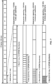
- a numerology with a higher subcarrier spacing has a shorter slot duration and, correspondingly, more slots per subframe.
- FIG. 7 illustrates this numerology-dependent slot duration and slots-per-subframe transmission structure (the numerology with a subcarrier spacing of 240 kHz is not shown in FIG. 7 for ease of illustration).
- a subframe in NR may be used as a numerology-independent time reference, while a slot may be used as the unit upon which uplink and downlink transmissions are scheduled.
- scheduling in NR may be decoupled from the slot duration and start at any OFDM symbol and last for as many symbols as needed for a transmission. These partial slot transmissions may be referred to as mini-slot or subslot transmissions.
- FIG. 8 illustrates an example configuration of a slot in the time and frequency domain for an NR carrier.
- the slot includes resource elements (REs) and resource blocks (RBs).
- An RE is the smallest physical resource in NR.
- An RE spans one OFDM symbol in the time domain by one subcarrier in the frequency domain as shown in FIG. 8 .
- An RB spans twelve consecutive REs in the frequency domain as shown in FIG. 8 .
- Such a limitation may limit the NR carrier to 50, 100, 200, and 400 MHz for subcarrier spacings of 15, 30, 60, and 120 kHz, respectively, where the 400 MHz bandwidth may be set based on a 400 MHz per carrier bandwidth limit.
- FIG. 8 illustrates a single numerology being used across the entire bandwidth of the NR carrier.
- multiple numerologies may be supported on the same carrier.
- a downlink BWP from a set of configured downlink BWPs may be linked with an uplink BWP from a set of configured uplink BWPs if a downlink BWP index of the downlink BWP and an uplink BWP index of the uplink BWP are the same.
- a UE may expect that a center frequency for a downlink BWP is the same as a center frequency for an uplink BWP.
- a base station may configure a UE with one or more control resource sets (CORESETs) for at least one search space.
- CORESETs control resource sets
- a search space is a set of locations in the time and frequency domains where the UE may find control information.
- the search space may be a UE-specific search space or a common search space (potentially usable by a plurality of UEs).
- a base station may configure a UE with a common search space, on a PCell or on a primary secondary cell (PSCell), in an active downlink BWP.
- a BS may configure a UE with one or more resource sets for one or more PUCCH transmissions.
- a UE may receive downlink receptions (e.g., PDCCH or PDSCH) in a downlink BWP according to a configured numerology (e.g., subcarrier spacing and cyclic prefix duration) for the downlink BWP.
- the UE may transmit uplink transmissions (e.g., PUCCH or PUSCH) in an uplink BWP according to a configured numerology (e.g., subcarrier spacing and cyclic prefix length for the uplink BWP).
- One or more BWP indicator fields may be provided in Downlink Control Information (DCI).
- DCI Downlink Control Information
- a value of a BWP indicator field may indicate which BWP in a set of configured BWPs is an active downlink BWP for one or more downlink receptions.
- the value of the one or more BWP indicator fields may indicate an active uplink BWP for one or more uplink transmissions.
- a base station may semi-statically configure a UE with a default downlink BWP within a set of configured downlink BWPs associated with a PCell. If the base station does not provide the default downlink BWP to the UE, the default downlink BWP may be an initial active downlink BWP. The UE may determine which BWP is the initial active downlink BWP based on a CORESET configuration obtained using the PBCH.
- a base station may configure a UE with a BWP inactivity timer value for a PCell.
- the UE may start or restart a BWP inactivity timer at any appropriate time.
- the UE may start or restart the BWP inactivity timer ( a ) when the UE detects a DCI indicating an active downlink BWP other than a default downlink BWP for a paired spectra operation; or ( b ) when a UE detects a DCI indicating an active downlink BWP or active uplink BWP other than a default downlink BWP or uplink BWP for an unpaired spectra operation.
- the UE may run the BWP inactivity timer toward expiration (for example, increment from zero to the BWP inactivity timer value, or decrement from the BWP inactivity timer value to zero).
- the UE may switch from the active downlink BWP to the default downlink BWP.
- a base station may semi-statically configure a UE with one or more BWPs.
- a UE may switch an active BWP from a first BWP to a second BWP in response to receiving a DCI indicating the second BWP as an active BWP and/or in response to an expiry of the BWP inactivity timer (e.g., if the second BWP is the default BWP).
- Downlink and uplink BWP switching may be performed independently in paired spectra. In unpaired spectra, downlink and uplink BWP switching may be performed simultaneously. Switching between configured BWPs may occur based on RRC signaling, DCI, expiration of a BWP inactivity timer, and/or an initiation of random access.
- FIG. 9 illustrates an example of bandwidth adaptation using three configured BWPs for an NR carrier.
- a UE configured with the three BWPs may switch from one BWP to another BWP at a switching point.
- the BWPs include: a BWP 902 with a bandwidth of 40 MHz and a subcarrier spacing of 15 kHz; a BWP 904 with a bandwidth of 10 MHz and a subcarrier spacing of 15 kHz; and a BWP 906 with a bandwidth of 20 MHz and a subcarrier spacing of 60 kHz.
- the BWP 902 may be an initial active BWP
- the BWP 904 may be a default BWP.
- the UE may switch between BWPs at switching points.
- the UE may switch from the BWP 902 to the BWP 904 at a switching point 908.
- the switching at the switching point 908 may occur for any suitable reason, for example, in response to an expiry of a BWP inactivity timer (indicating switching to the default BWP) and/or in response to receiving a DCI indicating BWP 904 as the active BWP.
- the UE may switch at a switching point 910 from active BWP 904 to BWP 906 in response receiving a DCI indicating BWP 906 as the active BWP.
- the UE may switch at a switching point 912 from active BWP 906 to BWP 904 in response to an expiry of a BWP inactivity timer and/or in response receiving a DCI indicating BWP 904 as the active BWP.
- the UE may switch at a switching point 914 from active BWP 904 to BWP 902 in response receiving a DCI indicating BWP 902 as the active BWP.
- UE procedures for switching BWPs on a secondary cell may be the same/similar as those on a primary cell. For example, the UE may use the timer value and the default downlink BWP for the secondary cell in the same/similar manner as the UE would use these values for a primary cell.
- CA carrier aggregation
- the aggregated carriers in CA may be referred to as component carriers (CCs).
- CCs component carriers
- the CCs may have three configurations in the frequency domain.
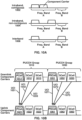
- FIG. 10A illustrates the three CA configurations with two CCs.
- the two CCs are aggregated in the same frequency band (frequency band A) and are located directly adjacent to each other within the frequency band.
- the two CCs are aggregated in the same frequency band (frequency band A) and are separated in the frequency band by a gap.
- the two CCs are located in frequency bands (frequency band A and frequency band B).
- up to 32 CCs may be aggregated.
- the aggregated CCs may have the same or different bandwidths, subcarrier spacing, and/or duplexing schemes (TDD or FDD).
- a serving cell for a UE using CA may have a downlink CC.
- one or more uplink CCs may be optionally configured for a serving cell.
- the ability to aggregate more downlink carriers than uplink carriers may be useful, for example, when the UE has more data traffic in the downlink than in the uplink.
- Configured SCells for a UE may be activated and deactivated based on, for example, traffic and channel conditions. Deactivation of an SCell may mean that PDCCH and PDSCH reception on the SCell is stopped and PUSCH, SRS, and CQI transmissions on the SCell are stopped. Configured SCells may be activated and deactivated using a MAC CE with respect to FIG. 4B . For example, a MAC CE may use a bitmap (e.g., one bit per SCell) to indicate which SCells (e.g., in a subset of configured SCells) for the UE are activated or deactivated. Configured SCells may be deactivated in response to an expiration of an SCell deactivation timer (e.g., one SCell deactivation timer per SCell).
- an SCell deactivation timer e.g., one SCell deactivation timer per SCell.
- FIG. 16D illustrates another example structure for modulation and up-conversion of a baseband signal to a carrier frequency.
- the baseband signal may be a complex-valued OFDM baseband signal for an antenna port. Filtering may be employed prior to transmission.
- a wireless device may receive from a base station one or more messages (e.g. RRC messages) comprising configuration parameters of a plurality of cells (e.g. primary cell, secondary cell).
- the wireless device may communicate with at least one base station (e.g. two or more base stations in dual-connectivity) via the plurality of cells.
- the one or more messages (e.g. as a part of the configuration parameters) may comprise parameters of physical, MAC, RLC, PCDP, SDAP, RRC layers for configuring the wireless device.
- the configuration parameters may comprise parameters for configuring physical and MAC layer channels, bearers, etc.
- the configuration parameters may comprise parameters indicating values of timers for physical, MAC, RLC, PCDP, SDAP, RRC layers, and/or communication channels.
- a timer may begin running once it is started and continue running until it is stopped or until it expires.
- a timer may be started if it is not running or restarted if it is running.
- a timer may be associated with a value (e.g. the timer may be started or restarted from a value or may be started from zero and expire once it reaches the value). The duration of a timer may not be updated until the timer is stopped or expires (e.g., due to BWP switching).
- a timer may be used to measure a time period/window for a process.
- a timer may be used to measure a time period/window for the procedure.
- a random access response window timer may be used for measuring a window of time for receiving a random access response.
- the time difference between two time stamps may be used.
- a timer is restarted, a process for measurement of time window may be restarted.
- Other example implementations may be provided to restart a measurement of a time window.
- a base station may transmit one or more MAC PDUs to a wireless device.
- a MAC PDU may be a bit string that is byte aligned (e.g., a multiple of eight bits) in length.
- bit strings may be represented by tables in which the most significant bit is the leftmost bit of the first line of the table, and the least significant bit is the rightmost bit on the last line of the table. More generally, the bit string may be read from left to right and then in the reading order of the lines.
- the bit order of a parameter field within a MAC PDU is represented with the first and most significant bit in the leftmost bit and the last and least significant bit in the rightmost bit.
- a MAC SDU may be a bit string that is byte aligned (e.g., a multiple of eight bits) in length.
- a MAC SDU may be included in a MAC PDU from the first bit onward.
- a MAC CE may be a bit string that is byte aligned (e.g., a multiple of eight bits) in length.
- a MAC subheader may be a bit string that is byte aligned (e.g., a multiple of eight bits) in length.
- a MAC subheader may be placed immediately in front of a corresponding MAC SDU, MAC CE, or padding.
- a MAC entity may ignore a value of reserved bits in a DL MAC PDU.
- a MAC PDU may comprise one or more MAC subPDUs.
- a MAC subPDU of the one or more MAC subPDUs may comprise: a MAC subheader only (including padding); a MAC subheader and a MAC SDU; a MAC subheader and a MAC CE; and/or a MAC subheader and padding.
- the MAC SDU may be of variable size.
- a MAC subheader may correspond to a MAC SDU, a MAC CE, or padding.
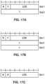
- the MAC subheader when a MAC subheader corresponds to a MAC SDU, a variable-sized MAC CE, or padding, the MAC subheader may comprise: an R field with a one bit length; an F field with a one-bit length; an LCID field with a multi-bit length; and/or an L field with a multi-bit length.
- FIG. 17A shows an example of a MAC subheader with an R field, an F field, an LCID field, and an L field.
- the LCID field may be six bits in length, and the L field may be eight bits in length.
- FIG. 17B shows example of a MAC subheader with an R field, a F field, an LCID field, and an L field.
- the LCID field may be six bits in length, and the L field may be sixteen bits in length.
- the MAC subheader may comprise: an R field with a two-bit length and an LCID field with a multi-bit length.
- FIG. 17C shows an example of a MAC subheader with an R field and an LCID field.
- the LCID field may be six bits in length
- the R field may be two bits in length.
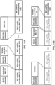
- FIG. 18A shows an example of a DL MAC PDU. Multiple MAC CEs, such as MAC CE 1 and 2, may be placed together. A MAC subPDU comprising a MAC CE may be placed before any MAC subPDU comprising a MAC SDU or a MAC subPDU comprising padding. FIG. 18B shows an example of a UL MAC PDU. Multiple MAC CEs, such as MAC CE 1 and 2, may be placed together. A MAC subPDU comprising a MAC CE may be placed after MAC subPDUs comprising a MAC SDU, e.g., after all MAC subPDUs comprising a MAC SDU. In addition, the MAC subPDU may be placed before a MAC subPDU comprising padding.
- a MAC entity of a base station may transmit one or more MAC CEs to a MAC entity of a wireless device.
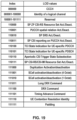
- FIG. 19 shows an example of multiple LCIDs that may be associated with the one or more MAC CEs.
- the one or more MAC CEs comprise at least one of: a semi-persistent (SP) zero-power (ZP) CSI-RS Resource Set Activation/Deactivation MAC CE, a PUCCH spatial relation Activation/Deactivation MAC CE, a SP SRS Activation/Deactivation MAC CE, a SP CSI reporting on PUCCH Activation/Deactivation MAC CE, a transmission configuration indication (TCI) State Indication for UE-specific PDCCH MAC CE, a TCI State Indication for UE-specific PDSCH MAC CE, an Aperiodic CSI Trigger State Subselection MAC CE, a SP CSI-RS/CSI-IM Resource Set Activation/Deactivation MAC CE, e.g.
- a MAC CE such as a MAC CE transmitted by a MAC entity of a base station to a MAC entity of a wireless device, may have an LCID in the MAC subheader corresponding to the MAC CE.
- Different MAC CE may have different LCID in the MAC subheader corresponding to the MAC CE.
- an LCID given by 111011 in a MAC subheader may indicate that a MAC CE associated with the MAC subheader is a long DRX command MAC CE.
- the MAC entity of the wireless device may transmit to the MAC entity of the base station one or more MAC CEs.
- FIG. 20 shows an example of the one or more MAC CEs.
- the one or more MAC CEs may comprise at least one of: a short buffer status report (BSR) MAC CE, a long BSR MAC CE, a C-RNTI MAC CE, a configured grant confirmation MAC CE, a single entry power headroom report (PHR) MAC CE, a multiple entry PHR MAC CE, a short truncated BSR, and/or a long truncated BSR.
- a MAC CE may have an LCID in the MAC subheader corresponding to the MAC CE.
- Different MAC CE may have different LCID in the MAC subheader corresponding to the MAC CE.
- an LCID given by 111011 in a MAC subheader may indicate that a MAC CE associated with the MAC subheader is a short-truncated command MAC CE.
- CA carrier aggregation
- two or more component carriers may be aggregated.
- a wireless device may simultaneously receive or transmit on one or more CCs, depending on capabilities of the wireless device, using the technique of CA.
- a wireless device may support CA for contiguous CCs and/or for non-contiguous CCs.
- CCs may be organized into cells. For example, CCs may be organized into one primary cell (PCell) and one or more secondary cells (SCells).
- PCell primary cell
- SCells secondary cells
- a wireless device When configured with CA, a wireless device may have one RRC connection with a network. During an RRC connection establishment/reestablishment/handover, a cell providing NAS mobility information may be a serving cell.
- a cell providing a security input may be a serving cell.
- the serving cell may denote a PCell.
- a base station may transmit, to a wireless device, one or more messages comprising configuration parameters of a plurality of one or more SCells, depending on capabilities of the wireless device.
- a base station and/or a wireless device may employ an activation/deactivation mechanism of an SCell to improve battery or power consumption of the wireless device.
- a base station may activate or deactivate at least one of the one or more SCells.
- the SCell may be deactivated unless an SCell state associated with the SCell is set to "activated" or "dormant".
- a wireless device may activate/deactivate an SCell in response to receiving an SCell Activation/Deactivation MAC CE.
- a base station may transmit, to a wireless device, one or more messages comprising an SCell timer (e.g., sCellDeactivationTimer).
- an SCell timer e.g., sCellDeactivationTimer.
- a wireless device may deactivate an SCell in response to an expiry of the SCell timer.
- the wireless device may activate the SCell.
- the wireless device may perform operations comprising SRS transmissions on the SCell; CQI/PMI/RI/CRI reporting for the SCell, e.g., CSI-RS resource indicator (CRI); PDCCH monitoring on the SCell; PDCCH monitoring for the SCell; and/or PUCCH transmissions on the SCell.
- the wireless device may start or restart a first SCell timer (e.g., sCellDeactivationTimer) associated with the SCell.
- a first SCell timer e.g., sCellDeactivationTimer
- the wireless device may start or restart the first SCell timer in the slot when the SCell Activation/Deactivation MAC CE activating the SCell has been received.
- the wireless device in response to the activating the SCell, may (re-)initialize one or more suspended configured uplink grants of a configured grant Type 1 associated with the SCell according to a stored configuration.
- the wireless device in response to the activating the SCell, may trigger PHR.
- the wireless device may deactivate the activated SCell.
- a first SCell timer e.g., sCellDeactivationTimer
- the wireless device may deactivate the activated SCell.
- the wireless device may stop the first SCell timer associated with the activated SCell.
- the wireless device may clear one or more configured downlink assignments and/or one or more configured uplink grants of a configured uplink grant Type 2 associated with the activated SCell.
- the wireless device may: suspend one or more configured uplink grants of a configured uplink grant Type 1 associated with the activated SCell; and/or flush HARQ buffers associated with the activated SCell.
- a wireless device may transmit PUSCH and SRS in a same slot.
- the base station may configure the wireless device to transmit the SRS after the transmission of the PUSCH (and the corresponding DM-RS).
- a base station may configure a wireless device with one or more SRS resource configurations.
- a higher layer parameter resourceType in a higher layer parameter SRS-Resource may be set to "periodic".
- a base station may configure a wireless device with one or more SRS resource sets (e.g., semi-persistent SRS resource sets).
- a higher layer parameter resourceType in a higher layer parameter SRS-Resource may be set to "semi-persistent".
- the wireless device may receive, from the base station, an activation command (e.g., SP SRS Activation/Deactivation MAC CE) for an SRS resource set of the one or more SRS resource sets.
- a PDSCH may carry the activation command.
- the wireless device may transmit an HARQ-ACK for the PDSCH in a slot n.
- the wireless device may apply one or more assumptions/actions for an SRS transmission of the SRS resource set starting from the slot n + 3 N slot subframe , ⁇ + 1 .
- the activation command may comprise one or more spatial relation assumptions for one or more SRS resources of the SRS resource set.
- a first field (e.g., Resource IDi) in the activation command may comprise an identifier of a resource (e.g., SS/PBCH block, NZP CSI-RS, SRS) used for spatial relationship derivation for an SRS resource of the one or more SRS resources.
- a Resource Serving Cell ID field indicating a serving cell may be present in the activation command.
- the reference RS may be an SS/PBCH block resource or a NZP CSI-RS resource.
- the reference RS (e.g., SS/PBCH block, NZP CSI-RS resource) may be configured on the serving cell.
- a Resource Serving Cell ID field indicating a serving cell and a Resource BWP ID field indicating an uplink BWP may be present in the activation command.
- the reference RS e.g., SRS resource
- the reference RS may be configured on the uplink BWP of the serving cell.
- the base station may configure the SRS resource set on an uplink BWP of a serving cell.
- a Resource Serving Cell ID field and a Resource BWP ID field may be absent in the activation command.
- the reference RS e.g., SRS resource
- the reference RS may be configured on the uplink BWP of the serving cell.
- the base station may configure an SRS resource in the (activated) SRS resource set with a higher layer parameter spatialRelationInfo.
- the wireless device may assume that a reference RS (e.g., indicated by an ID of the reference RS) in the activation command overrides a second reference RS configured in the higher layer parameter spatialRelationInfo.
- the wireless device may receive, from the base station, a deactivation command (e.g., SP SRS Activation/Deactivation MAC CE) for an (activated) SRS resource set of the one or more SRS resource sets.
- a PDSCH may carry the deactivation command.
- the wireless device may transmit an HARQ-ACK for the PDSCH in a slot n.
- the wireless device in response to the transmitting the HARQ-ACK for the PDSCH in the slot n, the wireless device may apply one or more assumptions/actions for a cessation of an SRS transmission of the (deactivated) SRS resource set starting from the slot n + 3 N slot subframe , ⁇ + 1 .
- a wireless device may activate a semi-persistent SRS resource configuration on an uplink BWP of a serving cell in response to receiving, from a base station, an activation command for the semi-persistent SRS resource configuration.
- the wireless device may not receive, from the base station, a deactivation command for the semi-persistent SRS resource configuration.
- the uplink BWP may be an active uplink BWP of the serving cell.
- the wireless device in response to the uplink BWP being the active uplink BWP of the serving cell and not receiving the deactivation command for the semi-persistent SRS resource configuration, the wireless device may consider the semi-persistent SRS resource configuration active. In an example, in response to the considering, the wireless device may transmit an SRS transmission, via the uplink BWP of the serving cell, according to the semi-persistent SRS resource configuration.
- the uplink BWP may not be an active uplink BWP of the serving cell.
- the uplink BWP not being the active uplink BWP may comprise the uplink BWP being deactivated in the serving cell.
- the wireless device may assume that the semi-persistent SRS configuration is suspended in the UL BWP of the serving cell.
- the semi-persistent SRS configuration being suspended in the UL BWP may comprise that the wireless device may reactivate the semi-persistent SRS configuration when the UL BWP becomes an active UL BWP of the serving cell.
- a first SRS resource of an SRS resource set may have a first time domain behavior (e.g., periodic, semi-persistent, or aperiodic, etc.).
- a second SRS resource of the SRS resource set may have a second time domain behavior (e.g., periodic, semi-persistent, or aperiodic, etc.).
- the wireless device in response to the first SRS resource and the second SRS resource being in the (same) SRS resource set, the wireless device may expect that the first time domain behavior and the second time behavior are the same.
- the wireless device in response to the first SRS resource and the second SRS resource being in the (same) SRS resource set, the wireless device may not expect that the first time domain behavior and the second time behavior are different.
- an SRS resource of an SRS resource set may have a first time domain behavior (e.g., periodic, semi-persistent, or aperiodic, etc.).
- the SRS resource set may have a second time domain behavior (e.g., periodic, semi-persistent, or aperiodic, etc.).
- the wireless device in response to the SRS resource being associated with the SRS resource set, the wireless device may expect that the first time domain behavior and the second time behavior are the same.
- the wireless device in response to the SRS resource and the SRS resource set being associated, the wireless device may not expect that the first time domain behavior and the second time behavior are different.
- the SRS resource being associated with the SRS resource set may comprise that the SRS resource set comprises the SRS resource.
- the SRS resource being associated with the SRS resource set may comprise that the SRS resource is an element of the SRS resource set.
- a base station may configure a wireless device with a PUCCH on at least one first symbol on a carrier (e.g., SUL, NUL).
- the PUCCH may carry/comprise one or more CSI reports.
- the PUCCH may carry/comprise one or more L1-RSRP reports.
- the PUCCH may carry/comprise HARQ-ACK and/or SR.
- the base station may configure the wireless device with an SRS configuration on the carrier.
- the SRS configuration may be a semi-persistent SRS configuration.
- the SRS configuration may be a periodic SRS configuration.
- the wireless device may determine that the PUCCH and an SRS transmission of the SRS configuration overlap in at least one symbol. In an example, the wireless device may determine that the at least one first symbol of the PUCCH and at least one second symbol of the SRS transmission of the SRS configuration may overlap in the at least one symbol. In an example, in response to the determining, the wireless device may not perform the SRS transmission, on the carrier, on the at least one symbol.
- a base station may configure a wireless device with a PUCCH on at least one first symbol on a carrier (e.g., SUL, NUL).
- the PUCCH may carry/comprise HARQ-ACK and/or SR.
- the base station may trigger an SRS configuration on the carrier.
- the SRS configuration may be an aperiodic SRS configuration.
- the wireless device may determine that the PUCCH and an SRS transmission of the SRS configuration overlap in at least one symbol.
- the wireless device may determine that the at least one first symbol of the PUCCH and at least one second symbol of the SRS transmission of the SRS configuration may overlap in the at least one symbol.
- the wireless device in response to the determining, the wireless device may not perform the SRS transmission, on the carrier, on the at least one symbol.
- the not performing the SRS transmission may comprise dropping the SRS transmission on the at least one symbol.
- the wireless device may perform the SRS transmission on at least one third symbol of the at least one second symbol. The at least one third symbol may not overlap with the at least one symbol.
- a base station may configure a wireless device with one or more cells. In an example, when a number of the one or more cells is one, the base station may configure the wireless device for a single-cell operation. In an example, when a number of the one or more cells is more than one, the base station may configure the wireless device for an operation with a carrier aggregation in a same frequency band (e.g., intra-band).
- a carrier aggregation e.g., intra-band
- the TCI state may provide a QCL assumption (e.g., an RS, an RS source, SS/PBCH block, CSI-RS).
- the TCI state may provide a QCL type (e.g., QCL-TypeA, QCL-TypeD, etc.).
- the wireless device may receive a DCI with a CSI request field from a base station.
- the wireless device may receive the DCI in a PDCCH.
- the wireless device may receive the DCI when monitoring the PDCCH.
- the DCI with the CSI request field may initiate/indicate/trigger an aperiodic trigger state of the one or more aperiodic trigger states.
- a codepoint of the CSI request field in the DCI may indicate the aperiodic trigger state.
- the aperiodic trigger state may comprise one or more report configurations (e.g., a list of NZP-CSI-RS-ResourceSet ) .
- the wireless device may receive a first DCI comprising a field indicating the first TCI of the first plurality of TCIs.
- the first DCI may comprise second field(s) indicating a downlink data scheduling assignment, e.g., time/frequency resource allocation for a PDSCH.
- the wireless device may receive the PDSCH based on the downlink data scheduling assignment and based on the first TCI.
- the wireless device may monitor (e.g., detect, receive) a PDCCH via the one or more CORESETs based on the first TCI.
- the wireless device may apply the second TCI before a time instance of transmitting the PUSCH scheduled by the second DCI, e.g., based on (depending on) the wireless device's capability on a processing time on successfully decoding a field in a DCI and applying information contents of the field to a relevant action.
- the wireless device may determine a transmission timing of a UCI via a PUCCH resource of the one or more PUCCH resources is before the time instance of transmitting the PUSCH.
- the wireless device may transmit the UCI via the PUCCH based on applying the second TCI.
- the base station may apply a third TCI (e.g., being used so far for the PUCCH resource, different from the second TCI) to receiving the UCI.
- Example embodiments may improve a reliability for an uplink beam management based on determining (e.g., defining) when to apply the second TCI to the at least one of uplink signal(s)/channel(s), e.g., the PUSCH and the one or more PUCCH resources (and the SRS, etc.), where the wireless device may apply the second TCI no earlier than (e.g., on and after) the time instance of transmitting the PUSCH.
- the wireless device may receive a third DCI comprising both fields for downlink common beam indication and uplink common beam indication.
- the third DCI may comprise a first field indicating the first TCI of the first plurality of TCIs.
- the third DCI may comprise a second field indicating the second TCI of the second plurality of TCIs.
- the third DCI may comprise third field(s) indicating a downlink data scheduling assignment, e.g., time/frequency resource allocation for a PDSCH.
- the wireless device may receive the PDSCH based on the downlink data scheduling assignment and based on the first TCI.
- the wireless device may monitor (e.g., detect, receive) a PDCCH via the one or more CORESETs based on the first TCI.
- the wireless device may transmit a PUSCH based on the second TCI.
- the wireless device may transmit a UCI via one or more PUCCH resources based on the second TCI.
- the third DCI comprising both fields for downlink common beam indication and uplink common beam indication may increase an overhead (e.g., increased bit-width/bit-length) of the third DCI due to comprising both the first field and the second field, which may reduce a reliability of successfully receiving the third DCI due to a decreased coding gain of the third DCI.
- the third DCI may improve an efficiency in terms of downlink resource utilization based on a simultaneous indication of the first TCI (as a downlink (common beam) reference) and the second TCI (as an uplink (common beam) reference) indicated by a single DCI (being the third DCI).
- a flexibility (based on indicating either the first TCI or the second TCI) may be achieved by comprising a selector (e.g., flag) in the DCI, where the selector may select between first activated TCIs from the first plurality of TCIs and second activated TCIs from the second plurality of TCIs.
- the selector may be explicitly comprised in the DCI, e.g., based on an additional field of comprising the selector, or via a part of the TCI field.
- the selector may be implicitly encoded (e.g., jointly encoded) in the TCI field, which may provide more flexibility to indicate the first TCI among a first number of first activated TCIs mapped to the first number of codepoints of the TCI field and the second TCI among a second number of second activated TCIs mapped to the second number of codepoints of the TCI field.
- Example embodiments may save overhead of the DCI based on not comprising an additional field (e.g., for indicating the second TCI separately) and may increase a flexibility/efficiency of comprising the TCI field (and the selector), based on mapping codepoints of the TCI field to different TCI (e.g., beam, transmission reference) pools, e.g., the first TCI pool (for DL) and the second TCI pool (for UL).
- TCI e.g., beam, transmission reference
- a base station may transmit one or more (MAC-CE) indications to determine the first number and the second number, e.g., before receiving the DCI.
- the wireless device may determine a first mapping between the first number of the first activated TCIs of the first plurality of TCIs and the first number of codepoints of the TCI field, and may determine a second mapping between the second number of the second activated TCIs of the second plurality of TCIs and the second number of codepoints of the TCI field.
- Example embodiments may improve an efficiency in terms of a downlink scheduling assignment and a (common) beam indication, based on the DCI further comprising second field(s) indicating a downlink data scheduling assignment, e.g., time/frequency resource allocation for a PDSCH.
- the wireless device may receive the PDSCH using the first TCI, based on determining the TCI field (and the selector) in the DCI indicates the first TCI, e.g., as a downlink (common beam) reference.
- the wireless device may receive the PDSCH using a third TCI (e.g., being used so far for downlink reception, different from the second TCI), based on determining the TCI field (and the selector) in the DCI indicates the second TCI, e.g., as an uplink (common beam) reference.
- Example embodiments may improve a flexibility in assigning (e.g., allocating, comprising), in the TCI field, how many first activated TCIs (e.g., the first number) from the first plurality of TCIs and how many second activated TCIs (e.g., the second number) from the second plurality of TCIs, based on the one or more (MAC-CE) indications.
- the one or more (MAC-CE) indications may indicate independent values of the first number and the second number, e.g., based on a restriction that the first number plus the second number is equal to (or less than) the length (e.g., the number of codepoints/states) of the TCI field.
- Example embodiments may save overhead of a DCI comprising the TCI field and improve an efficiency in indicating a common beam to a wireless device, based on that the TCI field may have a same length (bit-width) as a different TCI field comprising a joint (e.g., DL/UL unified) TCI(s) from a third plurality of TCIs (e.g., for joint/common/unified DL/UL beam indication).
- a joint e.g., DL/UL unified
- TCIs e.g., for joint/common/unified DL/UL beam indication
- a separate DL/UL TCI pool based beam management e.g., based on the first plurality of TCIs and the second plurality of TCIs
- a joint DL/UL TCI pool based beam management e.g., based on the third plurality of TCIs
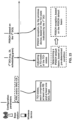
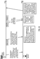
- FIG. 25 shows an example of common TCI indications, according to some embodiments.
- a wireless device may transmit uplink signals (e.g., to a base station or to a second wireless device), based on a value indicated by a TCI field of a DCI, where the TCI field may comprise a first set of codepoints mapped from a first plurality of TCIs (e.g., for downlink beam indication) and a second set of codepoints mapped from a second plurality of TCIs (e.g., for uplink beam indication), in accordance with embodiments of the present disclosure.
- a wireless device may receive, e.g., from a base station or from a second wireless device, one or more messages comprising configuration parameters for a first plurality of TCIs for downlink (beam) indication (e.g., a first TCI pool for DL) and a second plurality of TCIs for uplink (beam) indication (e.g., a second TCI pool for UL).
- a first plurality of TCIs for downlink (beam) indication e.g., a first TCI pool for DL
- a second plurality of TCIs for uplink (beam) indication e.g., a second TCI pool for UL.
- the one or more messages may further comprise configuration parameters for a mode (e.g., behavior, configuration mode, (feature) enabler, feature (by RRC enabler(s)), (feature) operation, method, scheme, (configuration) parameter, option, state, type, indication mechanism, and/or the like) for TCI indication (e.g., a first mode based on individual TCI-states, based on examples of FIG. 23 , or a second mode based on joint TCI(s), based on examples of FIG. 24 ).
- the one or more messages may comprise one or more RRC messages.
- the mode for TCI indication may be pre-determined (e.g., identified, defined, or pre-set) for the wireless device, e.g., based on a pre-defined (or pre-specified) rule, or based on the wireless device's capability-related information (and based on the wireless device's capability reporting, etc.).
- the mode for TCI indication may not be explicitly configured, activated, or indicated to the wireless device, where a functionality based on the mode for TCI indication may be applied to the wireless device without explicit signaling, based on example embodiments.
- the DCI may comprise a UL-grant scheduling an uplink data transmission (e.g., DCI format 0_1, DCI format 0_2, DCI format 0_0, and/or the like), e.g., comprising a CRC parity bits scrambled with a first RNTI (e.g., C-RNTI).
- a RNTI e.g., C-RNTI
- the one of the second TCI(s) may correspond to (e.g., be mapped to, be associated with) the value (e.g., codepoint) indicated by the TCI field, where the mapping between the value and the one of the second TCI(s) is indicated (e.g., activated, updated, mapped) by the one or more indications (e.g., via one or more MAC-CE messages).
- the wireless device may receive downlink data (e.g., via a PDSCH) scheduled by the DCI, e.g., using a third TCI which is different from the one of the second TCI(s).
- the uplink signals may comprise uplink control information (UCI), transmitted via an uplink control channel (e.g., a PUCCH).
- the uplink signals may comprise a sounding reference signal (SRS), e.g., transmitted via an SRS resource.
- SRS sounding reference signal
- the uplink signals may comprise a PRACH, e.g., a PDCCH-ordered PRACH transmission (in a given/configured BWP/CC).
- the uplink signals may comprise a PTRS, e.g., associated with a DMRS.
- Example embodiments may improve a flexibility of using a DCI to indicate either a first TCI of the first plurality of TCIs (as downlink (common beam) reference) or a second TCI of the second plurality of TCIs (as uplink (common beam) reference).
- Example embodiments may improve an efficiency in terms of a downlink scheduling assignment and a (common) beam indication, based on the DCI further comprising second field(s) indicating a downlink data scheduling assignment, e.g., time/frequency resource allocation for a PDSCH.
- the wireless device may receive the PDSCH using a third TCI (e.g., being used so far for downlink reception, different from the second TCI), based on determining the DCI indicates the second TCI, e.g., as an uplink (common beam) reference.
- a third TCI e.g., being used so far for downlink reception, different from the second TCI
- FIG. 26 shows an example of a TCI-indication MAC-CE, of N octets, of the one or more indications indicating (e.g., activating, updating, down-selecting) first TCI(s) of the first plurality of TCIs via a first message and second TCI(s) of the second plurality of TCIs via a second message, according to some embodiments of the present disclosure.
- the one or more indications may comprise one or more MAC-CE messages.
- a first MAC PDU subheader with a first LCID (e.g., '110101' as being reused based on 'TCI State Indication for UE-specific PDSCH', '110101' as being reused based on 'TCI State Indication for UE-specific PDCCH', a reserved LCID value, e.g., one ranging from '100001' to '101111', and/or the like, as shown in FIG. 19 ) may identify the TCI-indication MAC-CE of N octets.
- the TCI-indication MAC-CE of N octets may comprise at least a first number of T k fields and a link indicator (field), where the link indicator may (selectively) indicate either a downlink or an uplink (e.g., a 1-bit link indicator, or a 2-bit link indicator).
- the TCI-indication MAC-CE of N octets may have a fixed size.
- the link indicator may be set to 1 (or 0) indicating that the TCI-indication MAC-CE of N octets indicates (e.g., activates, updates, down-selects) first TCI(s) of the first plurality of TCIs (for downlink beam indication).
- the link indicator may activate one or more downlink TCIs.
- the link indicator may be set to 0 (or 1) indicating that the TCI-indication MAC-CE of N octets indicates (e.g., activates, updates, down-selects) second TCI(s) of the second plurality of TCIs (for uplink beam indication).
- the MAC-CE may activate one or more uplink TCIs.
- the link indicator may further indicate 'both downlink and uplink', e.g., a joint/common (downlink and uplink) TCI, where the link indicator may be a 2-bit link indicator.
- the link indicator may be set to 2 (or a predetermined value), e.g., '10', indicating that the TCI-indication MAC-CE of N octets indicates (e.g., activates, updates, down-selects) third TCI(s) of a third plurality of TCIs (e.g., for joint/common/unified DL/UL beam indication).
- the T k field may be set to 1 (e.g., by the base station, or by the second wireless device) indicating the TCI (T k ) with TCI-ID k is activated (e.g., selected, down-selected, indicated, updated) and mapped to a codepoint (of one or more codepoints) of a TCI field in a DCI.
- the T k field may be set to 0 indicating the TCI (T k ) with TCI-ID k is deactivated and is not mapped to the codepoint of the TCI field in the DCI.
- the codepoint to which the TCI (T k ) with TCI-ID k is mapped may be determined based on (or associated with) a value (e.g., 0, 1, or 2) indicated by the link indicator of the TCI-indication MAC-CE of N octets.
- the first mapping pattern (e.g., associated with a value of 1 of the link indicator) may comprise that the codepoint, to which the TCI (T k ) with TCI-ID k is mapped, is determined by its ordinal position among all the TCIs with T k field set to 1, e.g., and by mapping from a first (e.g., lowest) codepoint of the one or more codepoints of the TCI field, in a first pre-defined (or pre-configured) pattern across the one or more codepoints, e.g., in an increasing order of codepoints (as being the first pre-defined (or pre-configured) pattern) of the TCI field, e.g., shown as an example based on FIG.
- a first TCI with T k field set to 1 may be mapped to a codepoint value 0 (being the first (e.g., lowest) codepoint), a second TCI with T k field set to 1 may be mapped to a codepoint value 1, and so on.
- the second mapping pattern (e.g., associated with a value of 0 of the link indicator) may comprise that the codepoint, to which the TCI (T k ) with TCI-ID k is mapped, is determined by its ordinal position among all the TCIs with T k field set to 1, e.g., and by mapping from a second (e.g., highest) codepoint of the one or more codepoints of the TCI field, in a second pre-defined (or pre-configured) pattern across the one or more codepoints, e.g., in a decreasing order of codepoints (as being the second pre-defined (or pre-configured) pattern) of the TCI field, e.g., shown as an example based on FIG.
- a first TCI with T k field set to 1 may be mapped to a codepoint value 7, e.g., '111' of 3-bit TCI field (being the second (e.g., highest) codepoint), a second TCI with T k field set to 1 may be mapped to a codepoint value 6, e.g., '110' of 3-bit TCI field, and so on.
- the third mapping pattern may comprise that the codepoint, to which the TCI (T k ) with TCI-ID k is mapped, is determined by its ordinal position among all the TCIs with T k field set to 1, e.g., and by mapping from a third (e.g., a pre-defined, pre-configured) codepoint of the one or more codepoints of the TCI field, in a third pre-defined (or pre-configured) pattern across the one or more codepoints of the TCI field.
- a third e.g., a pre-defined, pre-configured
- a maximum number of activated TCIs may be pre-configured, or pre-defined (e.g., based on the TCI field size, e.g., the maximum number may be 2 B when the TCI field size is B-bit(s)).
- the TCI-indication MAC-CE of N octets may further comprise a Serving-Cell-ID field, as shown in FIG. 26 .
- the Serving-Cell-ID field may indicate an identity (ID) of a serving cell for which the TCI-indication MAC-CE applies.
- the length of the Serving-Cell-ID field may comprise 5 bits as an example (e.g., indicating one among up to 32 serving cells).
- the wireless device may determine that a serving cell indicated by the Serving-Cell-ID field is being configured as a part of a cell list (e.g., CC/BWP list) for simultaneous TCI update across the cell list, e.g., via a higher-layer parameter of simultaneousTCI-UpdateList1-r16, simultaneousTCI-UpdateList2-r16, simultaneousTCI-UpdateListNew, and/or the like.
- the wireless device may apply the TCI-indication MAC-CE to (all the) serving cells (configured) in the cell list (e.g., simultaneousTCI-UpdateList1-r16, simultaneousTCI-UpdateList2-r16, simultaneousTCI-UpdateListNew, and/or the like, respectively).
- the TCI-indication MAC-CE of N octets may further comprise a C field (e.g., a CORESET-Pool-ID field), as shown in FIG. 26 .
- the C field may indicate that a mapping between activated TCI(s) (e.g., all the TCIs with T k field set to 1) of the first number of T k fields and one or more codepoints of the TCI field of the DCI is specific to a CORESET group (or pool) index (e.g., CORESETPoolIndex, CORESET pool ID, a TRP ID of a TRP, ControlResourceSetId, coresetPoolIndex, and/or the like).
- CORESET group or pool index
- the C field (being) set to 1 may indicate that the TCI-indication MAC-CE of N octets may be applied for the DL transmission scheduled by a first CORESET with the CORESET pool ID equal to 1.
- the C field (being) set to 0 may indicate that the TCI-indication MAC-CE of N octets may be applied for the DL transmission scheduled by a second CORESET with the CORESET pool ID equal to 0.
- the wireless device may determine that a coresetPoolIndex is not configured for any CORESET.
- the wireless device e.g., a MAC entity of the wireless device
- the wireless device may determine that a serving cell indicated by the Serving-Cell-ID field (of the same TCI-indication MAC-CE of N octets) is configured in a cell list (e.g., CC/BWP list) that contains more than one serving cells (e.g., for simultaneous TCI update across the cell list, e.g., via a higher-layer parameter of simultaneousTCI-UpdateList1-r16, simultaneousTCI-UpdateList2-r16, simultaneousTCI-UpdateListNew, and/or the like).
- a serving cell indicated by the Serving-Cell-ID field of the same TCI-indication MAC-CE of N octets
- the wireless device In response to the determining that the serving cell indicated by the Serving-Cell-ID field is configured in the cell list, the wireless device (e.g., a MAC entity of the wireless device) may ignore the C field (when receiving the TCI-indication MAC-CE of N octets).
- the C field (e.g., a first bit of the TCI-indication MAC-CE of N octets) may comprise (e.g., be replaced by, be re-interpreted as, be reused by) the link indicator.
- the wireless device may determine (e.g., interpret) the first bit of the N octets of the TCI-indication MAC-CE as the link indicator. For example, the wireless device may interpret the first bit as the link indicator when the wireless device is configured with a single CORESET pool (e.g., group, set).
- the wireless device may interpret the first bit as the link indicator when the wireless device is not configured with a CORESET pool (e.g., group, set).
- Example embodiments may improve a flexibility in comprising the C field, where the C field may either indicate a CORESET group (or pool) or a value of the link indicator, e.g., based on the mode for TCI indication.
- Example embodiments may save overhead in signaling the link indicator, based on reusing bit(s) of the C field in the TCI-indication MAC-CE of N octets.
- the TCI-indication MAC-CE of N octets may further comprise a BWP-ID field.
- the BWP-ID field may indicate a DL-BWP for which the TCI-indication MAC-CE of N octets applies as a codepoint of a Bandwidth part indicator field in a DCI.
- the length of the BWP-ID field may be 2 bits.
- the wireless device may determine that a serving cell indicated by the Serving-Cell-ID field (of the same TCI-indication MAC-CE of N octets) is configured in a cell list (e.g., CC/BWP list) that contains more than one serving cells (e.g., for simultaneous TCI update across the cell list, e.g., via a higher-layer parameter of simultaneousTCI-UpdateList1-r16, simultaneousTCI-UpdateList2-r16, simultaneousTCI-UpdateListNew, and/or the like).
- a serving cell indicated by the Serving-Cell-ID field of the same TCI-indication MAC-CE of N octets
- the wireless device In response to the determining that the serving cell indicated by the Serving-Cell-ID field is configured in the cell list, the wireless device (e.g., a MAC entity of the wireless device) may ignore the BWP-ID field (when receiving the TCI-indication MAC-CE of N octets).
- the BWP-ID field (e.g., 7 th bit and 8 th bit of a first octet of N octets) may comprise (e.g., further include, be replaced by, be re-interpreted as, be reused by) the link indicator.
- the wireless device may determine (e.g., interpret) the 7 th bit and 8 th bit of the first octet of N octets, of the TCI-indication MAC-CE, as the link indicator.
- the wireless device may interpret the 7 th bit and 8 th bit (e.g., on which the BWP-ID field may be located) of the first octet of N octets (of the TCI-indication MAC-CE) as the link indicator.
- the link indicator (e.g., instead of the BWP-ID field) may comprise 2-bit, e.g., the same length/bit-width of the BWP-ID field, or 1-bit, etc.
- Example embodiments may improve a flexibility in comprising the BWP-ID field, where the BWP-ID field may either indicate a DL-BWP or a value of the link indicator, e.g., based on the mode for TCI indication.
- Example embodiments may save overhead in signaling the link indicator, based on reusing bit(s) of the BWP-ID field in the TCI-indication MAC-CE of N octets.
- the wireless device may determine a first DL-BWP for which the TCI-indication MAC-CE of N octets applies being a pre-defined (e.g., pre-configured, pre-determined) DL-BWP, e.g., a lowest(or highest)-indexed DL-BWP of a cell, a current DL-BWP of a cell, an active DL/UL BWP of a cell, a currently being used/activated DL-BWP of a cell, the most recent activated DL-BWP of a cell, one or more (e.g., all the) DL-BWPs of a cell, or (all the) DL-BWPs of one or more (e
- the wireless device may determine the BWP-ID field (e.g., the two last bits of the first octet), in the TCI-indication MAC-CE of N octets, indicates a DL-BWP for which the TCI-indication MAC-CE of N octets applies as a codepoint of a Bandwidth part indicator field in a DCI, where the first number of T k fields in the TCI-indication MAC-CE of N octets may indicate (e.g., activate, update, down-select) first TCI(s) of the first plurality of TCIs (e.g., for downlink beam indication).
- the BWP-ID field e.g., the two last bits of the first octet
- the wireless device may determine that the TCI-indication MAC-CE may further comprise M octets (e.g., in total, a length of the TCI-indication MAC-CE may be N + M octets), where the M octets may indicate (e.g., activate, update, down-select) second TCI(s) of the second plurality of TCIs (e.g., for uplink beam indication).
- M octets e.g., in total, a length of the TCI-indication MAC-CE may be N + M octets
- the M octets may indicate (e.g., activate, update, down-select) second TCI(s) of the second plurality of TCIs (e.g., for uplink beam indication).
- Example embodiments may improve an efficiency in signaling the TCI-indication MAC-CE based on that the TCI-indication MAC-CE may comprise, by a concatenation, N octets indicating first TCI(s) for downlink (common) beam indication and M octets indicating second TCI(s) for uplink (common) beam indication, e.g., where a portion (comprising T k fields (of all k's)) of the N octets may be duplicated to the M octets.
- Example embodiments may improve an efficiency in signaling the TCI-indication MAC-CE by simultaneously activating downlink (common) TCI(s) and uplink (common) TCIs, based on determining that the serving cell indicated by the Serving-Cell-ID field is not configured in the cell list (e.g., not applying a simultaneous TCI activation across multiple cells, but simultaneously activating downlink common TCI(s) and uplink common TCIs for the (single) serving cell).
- the pre-determined T k' field may not indicate an activation/deactivation status of a TCI with TCI-ID k', where the pre-determined T k' field may comprise (e.g., be replaced by, be re-interpreted as, be reused by) the link indicator.
- the wireless device may determine the T k' field, in the TCI-indication MAC-CE, is replaced by (e.g., re-interpreted as, reused by) the link indicator.
- the link indicator (instead of the T k' field) may comprise 1-bit, e.g., the same length/bitwidth of a T k field, or 2-bit, etc.
- the wireless device may assume that a TCI corresponding to T k' that is used for the link indicator may be not configured. For example, the TCI with an index value of k' may not be configured to the wireless device. For example, the wireless device may ignore the TCI with the index value of k'.
- a pre-determined e.g., pre-configured, pre-defined
- a first MAC-CE with a first LCID may activate one or more TCIs (e.g., first TCI(s) of the first plurality of TCIs) for downlink (common) beam update.
- a second MAC-CE with a second LCID may activate one or more TCIs (e.g., second TCI(s) of the second plurality of TCIs) for uplink (common) beam update.
- the first LCID may be different from the second LCID.
- the link indicator may be implicitly determined based on the first LCID or the second LCID.
- the first LCID may represent a downlink TCI update, e.g., may activate first TCI(s) of the first plurality of TCIs for downlink (common) beam indication.
- the second LCID may represent an uplink TCI update, e.g., may activate second TCI(s) of the second plurality of TCIs for uplink (common) beam indication.
- Example embodiments may save overhead in signaling the link indicator, based on using different LCID values for downlink (common) beam update and uplink (common) beam update.
- the TCI-indication MAC-CE of N octets may comprise a first octet and N-1 octets for one or more TCIs.
- the first octet may comprise 1 bit indicating a CORESET pool index, 1 bit of a link indicator (e.g., DL/UL), 4 bits of serving cell identifier, and 2 bits of BWP identifier (e.g., the BWP-ID field).
- the link indicator when the link indicator is used, the wireless device may not expect to be configured with more than 16 serving cells (e.g., based on the 4 bits of serving cell identifier).
- Example embodiments may save overhead in signaling the TCI-indication MAC-CE comprising the link indicator, based on comprising a reduced length of serving cell identifier (e.g., 4 bits, instead of 5 bits) within the first octet.
- a reduced length of serving cell identifier e.g., 4 bits, instead of 5 bits
- FIG. 27 shows an example of determining one or more codepoints of a TCI field of a DCI, in response to receiving the one or more indications, e.g., via a (TCI-indication) MAC-CE, indicating first TCI(s) of the first plurality of TCIs and second TCI(s) of the second plurality of TCIs, based on examples of FIG. 25 and FIG. 26 , according to some embodiments of the present disclosure.
- the first plurality of TCIs may comprise T 0 , T 1 , T 2 , ..., e.g., as downlink common (beam) reference.
- the second plurality of TCIs may comprise U 0 , U 1 , U 2 , ..., e.g., as uplink common (beam) reference.
- the wireless device may receive a first message of the one or more indications.
- the first message e.g., via a (TCI-indication) MAC-CE, may indicate a first value of the link indicator, where the first value may be set to 1, e.g., for downlink (common) beam indication.
- the first message may further indicate (e.g., activate, update, down-select) first TCI(s) of the first plurality of TCIs, based on the first value indicated by the link indicator.
- the first TCI(s) may comprise T 2 , T 5 , T 7 , T 8 , and T 14 of the first plurality of TCIs, e.g., where a value of 1 (for activation) may be set for the T 2 field, the T 5 field, the T 7 field, the T 8 field, and the T 14 field, and a value of 0 (for deactivation) may be set for other T k fields (for k ⁇ 2, 5, 7, 8, 14) in the first message, e.g., via the TCI-indication MAC-CE.
- the wireless device may determine that a first (e.g., lowest) codepoint of the one or more codepoints of the TCI field is a value '000' of the TCI field. In response to receiving the first message, the wireless device may apply (e.g., determine among the one or more mapping patterns) a first mapping pattern.
- a first e.g., lowest
- the wireless device may apply (e.g., determine among the one or more mapping patterns) a first mapping pattern.
- the first mapping pattern may comprise that the codepoint, to which the TCI (T k ) with TCI-ID k is mapped, is determined by its ordinal position among all the TCIs with T k field set to 1, e.g., and by mapping from the first (e.g., lowest) codepoint of the one or more codepoints, in a first pre-defined (or pre-configured) pattern across the one or more codepoints, e.g., in an increasing order of codepoints (as being the first pre-defined (or pre-configured) pattern).
- the wireless device may determine that the first TCI(s) comprising T 2 , T 5 , T 7 , T 8 , and T 14 comprise a first TCI (being the T 2 ), a second TCI (being the T 5 ), a third TCI (being the T 7 ), a fourth TCI (being the T 8 ), and a fifth TCI (being the T 14 ), based on its ordinal position among all the TCIs with T k field set to 1.
- the wireless device may determine that the first TCI (T 2 ) is mapped to a codepoint value '000', the second TCI (T 5 ) is mapped to a codepoint value '001', the third TCI (T 7 ) is mapped to a codepoint value '010', the fourth TCI (T 8 ) is mapped to a codepoint value '011', and the fifth TCI (T 14 ) is mapped to a codepoint value '100', in the TCI field, e.g., based on the increasing order of codepoints.
- the wireless device may receive a first DCI (e.g., scheduling downlink data) comprising the TCI field, via a downlink control channel (e.g., via a CORESET).
- a downlink control channel e.g., via a CORESET
- the wireless device may determine that a value indicated by the TCI field of the first DCI is the codepoint value '010' being mapped to the third TCI (T 7 ).
- the wireless device may receive downlink data (e.g., via a PDSCH) scheduled by the first DCI, using the third TCI (T 7 ).
- the receiving the downlink data (e.g., via the PDSCH) using the third TCI (T 7 ) may comprise receiving the downlink data (e.g., via the PDSCH) using a first spatial (domain) filter determined based on the third TCI (T 7 ).
- the wireless device may monitor (e.g., detect, receive) one or more PDCCHs (via one or more CORESETs) based on the first spatial (domain) filter, determined based on the third TCI (T 7 ) being as a downlink common (beam) reference.
- the wireless device may measure (e.g., receive) a CSI-RS based on the first spatial (domain) filter, determined based on the third TCI (T 7 ) being as a downlink common (beam) reference.
- the wireless device may receive a second message of the one or more indications.
- the second message e.g., via a (TCI-indication) MAC-CE, may indicate a second value of the link indicator, where the second value may be set to 0, e.g., for uplink (common) beam indication.
- the second message may further indicate (e.g., activate, update, down-select) second TCI(s) of the second plurality of TCIs, based on the second value indicated by the link indicator.
- the second TCI(s) may comprise U 4 , U 9 , and U 15 of the second plurality of TCIs, e.g., where a value of 1 (for activation) may be set for the U 4 field, the U 9 field, and the U 15 field, and a value of 0 (for deactivation) may be set for other U k fields (for U ⁇ 4, 9, 15) in the second message, e.g., via the TCI-indication MAC-CE.
- the wireless device may determine that a second (e.g., highest) codepoint of the one or more codepoints of the TCI field is a value '111' of the TCI field.
- the wireless device may determine that the second TCI(s) comprising U 4 , U 9 , and U 15 comprise a first TCI (being the U 4 ), a second TCI (being the U 9 ), and a third TCI (being the U 15 ), based on its ordinal position among all the TCIs with U k field set to 1.
- the wireless device may determine that the first TCI (U 4 ) is mapped to a codepoint value '111', the second TCI (U 9 ) is mapped to a codepoint value '110', and the third TCI (U 15 ) is mapped to a codepoint value '101', in the TCI field, e.g., based on the decreasing order of codepoints.
- the transmitting uplink signals via a PUSCH using the second TCI (U 9 ) may comprise transmitting the uplink signals via the PUSCH using the second spatial (domain) filter, in response to receiving a third DCI (e.g., different from the second DCI, e.g., after the second DCI or based on a reception timing of the second DCI) scheduling the uplink (data) signals of the PUSCH (as an uplink grant).
- the transmitting uplink signals via a PUSCH using the second TCI (U 9 ) may comprise transmitting the uplink signals via the PUSCH using the second spatial (domain) filter, based on a configured grant (semi-persistent scheduling) PUSCH, configured/activated via a separated signaling.
- the wireless device may receive downlink data (e.g., via a PDSCH) scheduled by the second DCI, based on the first spatial (domain) filter using the third TCI (T 7 ) (as being used so far or currently being used as a downlink common (beam) reference, e.g., based on the first DCI indicating the third TCI (T 7 ) of the first plurality of TCIs).
- downlink data e.g., via a PDSCH
- T 7 as being used so far or currently being used as a downlink common (beam) reference
- Example embodiments may reduce overhead for indicating the second TCI (U 9 ), based on that the second TCI (U 9 ) is not indicated by a separate DCI (e.g., is indicated by the second DCI scheduling the downlink data).
- Example embodiments may improve a flexibility that the second DCI indicating the second TCI (U 9 ) may further indicate the scheduling the downlink data, where a downlink reception, at the wireless device, on the scheduled downlink data may be performed by using the third TCI (T 7 ) which is different from the second TCI (U 9 ), e.g., is being used so far (currently being used) as a joint (e.g., common, unified) TCI for downlink reception, e.g., one of the first TCI(s) (comprising T 2 , T 5 , T 7 , T 8 , and T 14 ).
- FIG. 28A shows an example of determining one or more codepoints of a TCI field of a DCI, in response to receiving the one or more indications, e.g., via a (TCI-indication) MAC-CE, indicating first TCI(s) of the first plurality of TCIs and second TCI(s) of the second plurality of TCIs, based on examples of FIG. 25 , FIG. 26 , and FIG. 27 , according to some embodiments of the present disclosure.
- a (TCI-indication) MAC-CE indicating first TCI(s) of the first plurality of TCIs and second TCI(s) of the second plurality of TCIs, based on examples of FIG. 25 , FIG. 26 , and FIG. 27 , according to some embodiments of the present disclosure.
- the wireless device may receive a first message of the one or more indications.
- the first message e.g., via a (TCI-indication) MAC-CE, may indicate a first value of the link indicator, where the first value may be set to 1, e.g., for downlink (common) beam indication.
- the first message may further indicate (e.g., activate, update, down-select) first TCI(s) of the first plurality of TCIs, based on the first value indicated by the link indicator.
- the first TCI(s) may comprise a first activated TCI as T k1 , a second activated TCI as T k2 , a third activated TCI as T k3 , and a fourth activated TCI as T k4 of the first plurality of TCIs, e.g., where a value of 1 (for activation) may be set for a first T k field (corresponding to T k1 ), a second T k field (corresponding to T k2 ), a third T k field (corresponding to T k3 ), and a fourth T k field (corresponding to T k4 ), and a value of 0 (for deactivation) may be set for other T k fields (for k ⁇ k1, k2, k3, k4) in the first message, e.g., via the TCI-indication MAC-CE.
- the wireless device may receive a second message of the one or more indications.
- the second message e.g., via a (TCI-indication) MAC-CE, may indicate a second value of the link indicator, where the second value may be set to 0, e.g., for uplink (common) beam indication.
- the second message may further indicate (e.g., activate, update, down-select) second TCI(s) of the second plurality of TCIs, based on the second value indicated by the link indicator.
- the second TCI(s) may comprise a first activated TCI as U k1" , a second activated TCI as U k2" , a third activated TCI as U k3" , and a fourth activated TCI as U k4" of the second plurality of TCIs, e.g., where a value of 1 (for activation) may be set for a first U k field (corresponding to U k1" ), a second U k field (corresponding to U k2" ), a third U k field (corresponding to U k3" ), and a fourth U k field (corresponding to U k4" ), and a value of 0 (for deactivation) may be set for other U k fields (for k ⁇ k1", k2", k3", k4") in the second message, e.g., via the TCI-indication MAC-CE.
- the wireless device may determine that the TCI field of a DCI comprises at least two parts of information contents. The determining may be based on the mode (e.g., enabler, feature enabler, at least one parameter, configuration parameter) for TCI indication (based on examples of FIG. 25 , FIG. 26 , and FIG. 27 ).
- a first part (e.g., Part 1) of the at least two parts may comprise a selector (e.g., indicator, flag) indicating (e.g., selecting) a value of one or more values (e.g., comprising the first value and the second value) of the link indicator.
- a selector e.g., indicator, flag
- the DCI may comprise the first part (Part 1) separately (e.g., independently) from the TCI field, e.g., where the TCI field comprises the second part (without comprising the first part within the TCI field) and the first part is being comprised (outside of the TCI field) in the DCI.
- a second part (e.g., Part 2) of the at least two parts may comprise the first, second, third, fourth activated TCIs of either the first plurality of TCIs or the second plurality of TCIs.
- the wireless device may determine that the second part (Part 2) may comprise the first, second, third, fourth activated TCIs of the first plurality of TCIs, in response to determining a value (e.g., set to '1') indicated by the first part (in the same DCI) indicates the first value (e.g., set to 1 for DL) of the link indicator, e.g., based on the length (bit-width) of the second part (Part 2) as 2 bits.
- a value e.g., set to '1'
- the link indicator e.g., based on the length (bit-width) of the second part (Part 2) as 2 bits.
- the wireless device may determine that the second part (Part 2) may comprise the first, second, third, fourth activated TCIs of the second plurality of TCIs, in response to determining a value (e.g., set to '0') indicated by the first part (in the same DCI) indicates the second value (e.g., set to 0 for UL) of the link indicator, e.g., based on the length (bit-width) of the second part (Part 2) as 2 bits.
- a value e.g., set to '0'
- the link indicator e.g., based on the length (bit-width) of the second part (Part 2) as 2 bits.
- a first length (bitwidth, e.g., 1-bit) of the first part (Part 1) plus a second length (bitwidth, e.g., 2-bit) of the second part (Part 2) may be equal (or less than) a length (bitwidth, e.g., 3-bit) of the DCI field (e.g., TCI field) shown in examples of FIG. 23 .
- Example embodiments may increase an efficiency (and flexibility) in selecting (e.g., indicating, configuring, operating, switching) between a first mode (e.g., enabler, feature enabler, at least one parameter, configuration parameter) for TCI indication based on the DCI field (e.g., 3-bit) shown in examples of FIG. 23 and a second mode for TCI indication based on a TCI field comprising the first part and the second part, e.g., using the same DCI format (with the same field size of the TCI field between the first mode and the second mode).
- a first mode e.g.
- the wireless device may determine that a first codepoint of the one or more codepoints of the TCI field is a value '00' of Part 2 of the TCI field. In response to receiving the first message, the wireless device may apply (e.g., determine among the one or more mapping patterns) a first mapping pattern.
- the first mapping pattern may comprise that the codepoint, to which the TCI (T k ) with TCI-ID k is mapped, is determined by its ordinal position among all the TCIs with T k field set to 1, e.g., and by mapping from the first codepoint, in a first pre-defined (or pre-configured) pattern across one or more codepoints of Part 2, e.g., in an increasing order of codepoints (as being the first pre-defined (or pre-configured) pattern).
- the wireless device may determine that the first TCI(s) comprising the first, second, third, fourth activated TCIs of the first plurality of TCIs, based on its ordinal position among all the TCIs with T k field set to 1.
- the second mapping pattern may comprise that the codepoint, to which the TCI (U k ) with TCI-ID k is mapped, is determined by its ordinal position among all the TCIs with U k field set to 1, e.g., and by mapping from the second codepoint, in a second pre-defined (or pre-configured) pattern across one or more codepoints of Part 2, e.g., in an increasing (or decreasing, etc.) order of codepoints (as being the second pre-defined (or pre-configured) pattern).
- the wireless device may determine that the second TCI(s) comprising the first, second, third, fourth activated TCIs of the second plurality of TCIs, based on its ordinal position among all the TCIs with U k field set to 1.
- Example embodiments may increase an efficiency (and flexibility) in dynamically selecting (e.g., indicating, switching) between the first TCI(s) and the second TCI(s), based on a value indicated by the first part (Part 1) of the TCI field.
- Example embodiments may improve an efficiency and save overhead of indicating a TCI from either the first TCI(s) or the second TCI(s), based on sharing (e.g., re-using) bit(s) for the second part (Part 2) comprising either the first TCI(s) or the second TCI(s), where the comprising either the first TCI(s) or the second TCI(s) may be determined (e.g., selected) based on the value indicated by the first part (Part 1) of the TCI field.
- the wireless device may receive a first DCI (e.g., scheduling downlink data) comprising the TCI field (which comprises the Part 1 and the Part 2), via a downlink control channel (e.g., via a CORESET).
- a first value e.g., selector, flag
- the wireless device may determine that a first value (e.g., selector, flag) indicated by the Part 1 of the TCI field of the first DCI is the codepoint '1' indicating (e.g., selecting) the first TCI(s), e.g., for DL.
- the wireless device may determine that a second value indicated by the Part 2 of the TCI field of the (same) first DCI is the codepoint value '10' being mapped to the third activated TCI (T k3 ) of the first TCI(s) of the first plurality of TCIs, based on the first value indicated by the Part 1 of the TCI field of the first DCI.
- the wireless device may receive downlink data (e.g., via a PDSCH) scheduled by the first DCI, using the third activated TCI (T k3 ).
- the receiving the downlink data (e.g., via the PDSCH) using the third activated TCI (T k3 ) may comprise receiving the downlink data (e.g., via the PDSCH) using a first spatial (domain) filter determined based on the third activated TCI (T k3 ).
- the wireless device may monitor (e.g., detect, receive) one or more PDCCHs (via one or more CORESETs) based on the first spatial (domain) filter, determined based on the third activated TCI (T k3 ) being as a downlink common (beam) reference.
- the wireless device may measure (e.g., receive) a CSI-RS based on the first spatial (domain) filter, determined based on the third activated TCI (T k3 ) being as a downlink common (beam) reference.
- the wireless device may receive a second DCI (e.g., scheduling downlink data) comprising the TCI field (which comprises the Part 1 and the Part 2), via a downlink control channel (e.g., via a CORESET).
- a second DCI e.g., scheduling downlink data
- the wireless device may determine that a first value indicated by the Part 1 of the TCI field of the second DCI is the codepoint '0' indicating (e.g., selecting) the second TCI(s), e.g., for UL.
- the wireless device may determine that a second value indicated by the Part 2 of the TCI field of the (same) second DCI is the codepoint value '11' being mapped to the fourth activated TCI (U k4" ) of the second TCI(s) of the second plurality of TCIs, based on the first value indicated by the Part 1 of the TCI field of the second DCI.
- the wireless device may transmit uplink signals using the fourth activated TCI (U k4" ), in response to the determining.
- the transmitting the uplink signals e.g., via at least one of: a PUSCH, a PUCCH, and an SRS resource (and a PRACH, and a PTRS, etc.), using the fourth activated TCI (U k4" ) may comprise transmitting the uplink signals using a second spatial (domain) filter determined based on the fourth activated TCI (U k4" ).
- the transmitting uplink signals via a PUSCH using the fourth activated TCI (U k4" ) may comprise transmitting the uplink signals via the PUSCH using the second spatial (domain) filter, in response to receiving a third DCI (e.g., different from the second DCI, e.g., after the second DCI or based on a reception timing of the second DCI) scheduling the uplink (data) signals of the PUSCH (as an uplink grant).
- a third DCI e.g., different from the second DCI, e.g., after the second DCI or based on a reception timing of the second DCI
- the transmitting uplink signals via a PUSCH using the fourth activated TCI (U k4" ) may comprise transmitting the uplink signals via the PUSCH using the second spatial (domain) filter, based on a configured grant (semi-persistent scheduling) PUSCH, configured/activated via a separated signaling.
- the transmitting uplink signals via a PUCCH using the fourth activated TCI (U k4" ) may comprise transmitting a UCI (as a HARQ transmission) via the PUCCH using the second spatial (domain) filter, in response to receiving downlink data, where the HARQ transmission is based on the downlink data (e.g., for an acknowledgement of successfully receiving the downlink data).
- the transmitting uplink signals via a PUCCH using the fourth activated TCI (U k4" ) may comprise transmitting a UCI (e.g., CSI reporting, scheduling request, etc.) via the PUCCH using the second spatial (domain) filter, based on a pre-configured PUCCH transmission via a separate (higher-layer) signaling.
- Example embodiments may reduce overhead for indicating the fourth activated TCI (U k4" ), based on that the fourth activated TCI (U k4" ) is not indicated by a separate DCI (e.g., is indicated by the second DCI scheduling the downlink data).
- the TCI-activation-status field may comprise one or more T k fields, each indicating an activation/deactivation status of a TCI with TCI-ID k.
- the TCI-activation-status field of the first message may indicate the first TCIs of the first plurality of TCIs, based on a first value indicated by the link indicator of the first message.
- the TCI-activation-status field of the first message may indicate the second TCIs of the second plurality of TCIs, based on a second value indicated by the link indicator of the first message.
Landscapes
- Engineering & Computer Science (AREA)
- Signal Processing (AREA)
- Computer Networks & Wireless Communication (AREA)
- Mobile Radio Communication Systems (AREA)
Applications Claiming Priority (3)
| Application Number | Priority Date | Filing Date | Title |
|---|---|---|---|
| US202163136493P | 2021-01-12 | 2021-01-12 | |
| PCT/US2022/012113 WO2022155198A1 (fr) | 2021-01-12 | 2022-01-12 | Indication d'un faisceau commun sur la base d'une sélection de liaison |
| EP22702357.9A EP4260506B1 (fr) | 2021-01-12 | 2022-01-12 | Indication d'un faisceau commun sur la base d'une sélection de liaison |
Related Parent Applications (1)
| Application Number | Title | Priority Date | Filing Date |
|---|---|---|---|
| EP22702357.9A Division EP4260506B1 (fr) | 2021-01-12 | 2022-01-12 | Indication d'un faisceau commun sur la base d'une sélection de liaison |
Publications (2)
| Publication Number | Publication Date |
|---|---|
| EP4576602A2 true EP4576602A2 (fr) | 2025-06-25 |
| EP4576602A3 EP4576602A3 (fr) | 2025-09-17 |
Family
ID=80168285
Family Applications (2)
| Application Number | Title | Priority Date | Filing Date |
|---|---|---|---|
| EP22702357.9A Active EP4260506B1 (fr) | 2021-01-12 | 2022-01-12 | Indication d'un faisceau commun sur la base d'une sélection de liaison |
| EP25175280.4A Pending EP4576602A3 (fr) | 2021-01-12 | 2022-01-12 | Indication de faisceau commun basée sur une sélection de liaison |
Family Applications Before (1)
| Application Number | Title | Priority Date | Filing Date |
|---|---|---|---|
| EP22702357.9A Active EP4260506B1 (fr) | 2021-01-12 | 2022-01-12 | Indication d'un faisceau commun sur la base d'une sélection de liaison |
Country Status (7)
| Country | Link |
|---|---|
| US (2) | US12058700B2 (fr) |
| EP (2) | EP4260506B1 (fr) |
| JP (1) | JP7671464B2 (fr) |
| KR (1) | KR20230130045A (fr) |
| CN (1) | CN117178491A (fr) |
| CA (1) | CA3206010A1 (fr) |
| WO (1) | WO2022155198A1 (fr) |
Families Citing this family (37)
| Publication number | Priority date | Publication date | Assignee | Title |
|---|---|---|---|---|
| US11510082B2 (en) | 2019-03-29 | 2022-11-22 | Qualcomm Incorporated | Beam indication reuse |
| US11665692B2 (en) | 2020-01-16 | 2023-05-30 | Samsung Electronics Co., Ltd. | Method and apparatus for beam indication in a multi-beam system |
| JP7724277B2 (ja) * | 2020-08-05 | 2025-08-15 | インターデイジタル パテント ホールディングス インコーポレイテッド | Tci状態グループに基づくビーム指示 |
| CN117063563A (zh) * | 2021-01-14 | 2023-11-14 | 株式会社Ntt都科摩 | 终端、无线通信方法以及基站 |
| US12382464B2 (en) * | 2021-01-14 | 2025-08-05 | Qualcomm Incorporated | Techniques for common beam update rules for scheduled communications |
| KR102514448B1 (ko) * | 2021-01-18 | 2023-03-29 | 엘지전자 주식회사 | 무선 통신 시스템에서 무선 신호 송수신 방법 및 장치 |
| US20220271821A1 (en) * | 2021-02-23 | 2022-08-25 | Samsung Electronics Co., Ltd. | Method and apparatus for signaling of inter-cell beam management |
| CN117099352A (zh) * | 2021-03-31 | 2023-11-21 | 中兴通讯股份有限公司 | 用于确定跨分量载波的波束信息的方法、装置和系统 |
| US12432716B2 (en) * | 2021-03-31 | 2025-09-30 | Qualcomm Incorporated | Dynamic reconfiguration of uplink control channel resources for a scheduling request |
| WO2022235800A1 (fr) * | 2021-05-04 | 2022-11-10 | Ofinno, Llc | Multiplexage basé sur un faisceau sur l'accès à un canal |
| CN115499856B (zh) * | 2021-06-17 | 2025-04-11 | 华为技术有限公司 | 一种信息传输方法及通信装置 |
| WO2023010518A1 (fr) * | 2021-08-06 | 2023-02-09 | Apple Inc. | Accusé de réception de rapport de faisceau |
| EP4393233A4 (fr) * | 2021-08-24 | 2025-04-23 | Qualcomm Incorporated | Sélection d'état d'indicateur de configuration de transmission sans indication |
| US20240314807A1 (en) * | 2021-08-27 | 2024-09-19 | Qualcomm Incorporated | Panel switching indication in multiple transmission/reception point (multi-trp) operations |
| CN115866107B (zh) * | 2021-09-23 | 2025-05-13 | 维沃移动通信有限公司 | 传输处理方法、装置、终端、网络侧设备及存储介质 |
| US12563543B2 (en) * | 2021-12-29 | 2026-02-24 | Samsung Electronics Co., Ltd. | Method and apparatus for timing of cross carrier beam indications |
| US20230319846A1 (en) * | 2022-04-04 | 2023-10-05 | Samsung Electronics Co., Ltd. | Method and apparatus of indicating dynamic beam switching via downlink control information |
| US12166719B2 (en) * | 2022-05-18 | 2024-12-10 | Telefonaktiebolaget Lm Ericsson (Publ) | User equipment, network node and methods in a wireless communications network |
| US12439418B2 (en) * | 2022-08-01 | 2025-10-07 | Apple Inc. | Mapping unified transmission states for multipoint control channel reception using rules |
| EP4349109A4 (fr) * | 2022-08-05 | 2024-11-27 | ZTE Corporation | Cadre d'indication de faisceau unifié pour utiliser de multiples points d'émission-réception |
| EP4569645A1 (fr) * | 2022-08-09 | 2025-06-18 | Telefonaktiebolaget LM Ericsson (publ) | Conditions de déclenchement pour rapport de faisceau ue commandé par événement |
| KR20240125845A (ko) * | 2022-08-10 | 2024-08-20 | 지티이 코포레이션 | 전송 구성 표시자 상태를 결정하기 위한 방법 및 시스템 |
| WO2024050774A1 (fr) * | 2022-09-08 | 2024-03-14 | 北京小米移动软件有限公司 | Procédé/appareil/dispositif de détermination d'informations et support d'enregistrement |
| EP4586720A4 (fr) * | 2022-09-09 | 2025-10-22 | Beijing Xiaomi Mobile Software Co Ltd | Procédé et appareil de détermination d'état tci, et dispositif et support de stockage |
| EP4371255A4 (fr) * | 2022-09-29 | 2025-03-05 | ZTE Corporation | Indication de configuration de transmission dans une mobilité sans fil |
| US20240259172A1 (en) * | 2023-01-26 | 2024-08-01 | Qualcomm Incorporated | Unified tci for dci format 1_2 |
| WO2024172370A1 (fr) * | 2023-02-13 | 2024-08-22 | 엘지전자 주식회사 | Procédé et appareil d'émission et de réception de signal dans un système de communication sans fil |
| CN121080049A (zh) * | 2023-02-15 | 2025-12-05 | Lg电子株式会社 | 用于在无线通信系统中根据与节能相关的模式执行通信的设备及方法 |
| US20240322984A1 (en) * | 2023-03-24 | 2024-09-26 | Samsung Electronics Co., Ltd. | Mac control element for multi-transmission/reception point operation |
| US20240340998A1 (en) * | 2023-04-05 | 2024-10-10 | Qualcomm Incorporated | Dynamic indication to skip channel reception or transmission |
| US20250233627A1 (en) * | 2024-01-17 | 2025-07-17 | Qualcomm Incorporated | Enhancement of user equipment (ue) selection for uplink aggregation |
| WO2025172520A1 (fr) * | 2024-02-16 | 2025-08-21 | Nokia Technologies Oy | Commutateur basé sur une liaison montante d'état tci indiqué dans une structure tci unifiée |
| GB2638282A (en) * | 2024-02-19 | 2025-08-20 | Nokia Technologies Oy | TCI selection with beam prediction |
| US20250293843A1 (en) * | 2024-03-12 | 2025-09-18 | Samsung Electronics Co., Ltd. | Spatial relation indication |
| US20250294483A1 (en) * | 2024-03-14 | 2025-09-18 | Qualcomm Incorporated | Synchronization signal block communications |
| WO2025222361A1 (fr) * | 2024-04-23 | 2025-10-30 | Qualcomm Incorporated | Sélection d'un état d'indication de configuration de transmission pour une transmission de canal physique d'accès aléatoire |
| US20250350418A1 (en) * | 2024-05-10 | 2025-11-13 | Acer Incorporated | Method used by user equipment, method used by network device, and user equipment |
Citations (1)
| Publication number | Priority date | Publication date | Assignee | Title |
|---|---|---|---|---|
| WO2020164600A1 (fr) | 2019-02-15 | 2020-08-20 | 华为技术有限公司 | Procédé et appareil d'indication d'informations |
Family Cites Families (34)
| Publication number | Priority date | Publication date | Assignee | Title |
|---|---|---|---|---|
| CN110475360B (zh) * | 2018-05-10 | 2023-05-02 | 华硕电脑股份有限公司 | 无线通信系统中上行链路传送的波束指示的方法和设备 |
| WO2019240530A1 (fr) | 2018-06-15 | 2019-12-19 | Samsung Electronics Co., Ltd. | Procédé et appareil permettant la réalisation d'une communication dans un réseau hétérogène |
| US11051181B2 (en) | 2018-06-18 | 2021-06-29 | Qualcomm Incorporated | Uplink transmission adaptation based on transmission configuration state |
| JP7206403B2 (ja) * | 2019-02-14 | 2023-01-17 | アップル インコーポレイテッド | Cli-rssi測定リソース構成 |
| KR102859936B1 (ko) * | 2019-03-28 | 2025-09-12 | 삼성전자주식회사 | 무선 통신 시스템에서 복수의 빔을 통해 신호를 송수신하는 방법 및 장치 |
| US11510082B2 (en) | 2019-03-29 | 2022-11-22 | Qualcomm Incorporated | Beam indication reuse |
| JP7387729B2 (ja) | 2019-05-17 | 2023-11-28 | 株式会社Nttドコモ | 端末、無線通信方法、基地局及びシステム |
| US11438922B2 (en) * | 2019-07-19 | 2022-09-06 | Qualcomm Incorporated | MAC-CE duplication in packet duplication |
| CN118945783A (zh) * | 2019-08-16 | 2024-11-12 | 中兴通讯股份有限公司 | 一种无线通信方法、装置和计算机可读介质 |
| US12563410B2 (en) * | 2019-08-27 | 2026-02-24 | Samsung Electronics Co., Ltd. | Method and apparatus for multi-beam operations |
| EP4011153A4 (fr) * | 2019-10-30 | 2022-08-10 | Guangdong Oppo Mobile Telecommunications Corp., Ltd. | Appareil et procédé pouvant être mis en oeuvre pour une unité de données de paquet de commande d'accès au support |
| US11290174B2 (en) | 2019-10-31 | 2022-03-29 | Qualcomm Incorporated | Beam selection for communication in a multi-transmit-receive point deployment |
| CN110856258B (zh) * | 2019-11-08 | 2022-02-22 | 中国信息通信研究院 | 一种多点发送波束指示方法和设备 |
| CN111901808B (zh) * | 2020-01-17 | 2025-01-07 | 中兴通讯股份有限公司 | 参数信息确定方法、通信节点和存储介质 |
| US11937222B2 (en) * | 2020-02-06 | 2024-03-19 | Qualcomm Incorporated | User equipment (UE) capability on band group sharing of same quasi co-location (QCL) parameter |
| CN113316253A (zh) | 2020-02-27 | 2021-08-27 | 索尼公司 | 用于无线通信的电子设备和方法、计算机可读存储介质 |
| US12231207B2 (en) * | 2020-03-03 | 2025-02-18 | Sharp Kabushiki Kaisha | Methods and apparatus for beam failure detection reference signal determination |
| WO2021198988A1 (fr) * | 2020-04-01 | 2021-10-07 | Telefonaktiebolaget Lm Ericsson (Publ) | Fiabilité de trp multiples de pusch à indication de tci en ul |
| WO2021223216A1 (fr) * | 2020-05-08 | 2021-11-11 | Qualcomm Incorporated | Système et procédé de mise à jour de faisceau basée sur une composante porteuse de groupe |
| CN113630224B (zh) * | 2020-05-09 | 2023-06-23 | 展讯通信(上海)有限公司 | 波束指示方法及装置、计算机可读存储介质 |
| EP4162614B1 (fr) * | 2020-06-09 | 2025-08-20 | Qualcomm Incorporated | Techniques pour signal de référence de liaison montante permettant des communications sans fil non basées sur un livre de codes |
| US12489582B2 (en) * | 2020-07-10 | 2025-12-02 | Qualcomm Incorporated | User equipment (UE) physical layer measurement reporting in secondary cell group (SCG) dormancy |
| US11895681B2 (en) | 2020-08-18 | 2024-02-06 | Samsung Electronics Co., Ltd. | Method and apparatus for fast beam indication |
| WO2022051927A1 (fr) | 2020-09-09 | 2022-03-17 | Qualcomm Incorporated | Procédés et appareil pour l'activation d'états de tci de dl/ul conjointes pour mdci |
| WO2022052954A1 (fr) * | 2020-09-09 | 2022-03-17 | Qualcomm Incorporated | Activation d'états de tci dl/ul conjoints pour mdci |
| WO2022061507A1 (fr) * | 2020-09-22 | 2022-03-31 | Oppo广东移动通信有限公司 | Procédé de transmission d'informations, dispositifs, et support de stockage |
| US20230397193A1 (en) * | 2020-09-29 | 2023-12-07 | Lenovo (Beijing) Limited | Joint tci states for dl and ul beam indication |
| WO2022086387A1 (fr) * | 2020-10-19 | 2022-04-28 | Telefonaktiebolaget Lm Ericsson (Publ) | Messages entre groupes de cellules pour équipement utilisateur fonctionnant en multi-connectivité |
| CN116349157A (zh) * | 2020-10-22 | 2023-06-27 | 华为技术有限公司 | 用于多波束操作的方法和装置 |
| EP4274319A4 (fr) * | 2020-12-29 | 2024-11-27 | LG Electronics Inc. | Procédé permettant de transmettre et de recevoir un signal en liaison montante dans un système de communication sans fil et dispositif associé |
| US20240064770A1 (en) | 2020-12-30 | 2024-02-22 | Telefonaktiebolaget Lm Ericsson (Publ) | Dci based dl tci state and ul tci state activation |
| CN114698082A (zh) * | 2020-12-31 | 2022-07-01 | 华硕电脑股份有限公司 | 无线通信系统中多trp的功率余量报告的方法和设备 |
| EP4272363B1 (fr) * | 2021-01-04 | 2025-06-18 | Guangdong Oppo Mobile Telecommunications Corp., Ltd. | Procédés et systèmes d'indicateur de configuration de transmission (tci) de liaison descendante et de liaison montante |
| US12289781B2 (en) * | 2021-01-11 | 2025-04-29 | Electronics And Telecommunications Research Institute | Method and apparatus for dual connectivity management in wireless communication system |
-
2022
- 2022-01-12 JP JP2023541926A patent/JP7671464B2/ja active Active
- 2022-01-12 WO PCT/US2022/012113 patent/WO2022155198A1/fr not_active Ceased
- 2022-01-12 EP EP22702357.9A patent/EP4260506B1/fr active Active
- 2022-01-12 KR KR1020237026633A patent/KR20230130045A/ko active Pending
- 2022-01-12 EP EP25175280.4A patent/EP4576602A3/fr active Pending
- 2022-01-12 CN CN202280009708.6A patent/CN117178491A/zh active Pending
- 2022-01-12 CA CA3206010A patent/CA3206010A1/fr active Pending
-
2023
- 2023-05-16 US US18/198,109 patent/US12058700B2/en active Active
-
2024
- 2024-08-01 US US18/792,136 patent/US20240397523A1/en active Pending
Patent Citations (2)
| Publication number | Priority date | Publication date | Assignee | Title |
|---|---|---|---|---|
| WO2020164600A1 (fr) | 2019-02-15 | 2020-08-20 | 华为技术有限公司 | Procédé et appareil d'indication d'informations |
| EP3897057A1 (fr) | 2019-02-15 | 2021-10-20 | Huawei Technologies Co., Ltd. | Procédé et appareil d'indication d'informations |
Non-Patent Citations (2)
| Title |
|---|
| LG ELECTRONICS: "Feature lead summary of Enhancements on Multibeam Operations", 3GPP DRAFT R1-1909486, 3GPP TSG RAN WG1 MEETING #98, 26 August 2019 (2019-08-26) |
| ZTE: "Enhancements on multi-beam operation", 3GPP DRAFT R1-1908192 |
Also Published As
| Publication number | Publication date |
|---|---|
| WO2022155198A1 (fr) | 2022-07-21 |
| KR20230130045A (ko) | 2023-09-11 |
| US12058700B2 (en) | 2024-08-06 |
| CN117178491A (zh) | 2023-12-05 |
| JP2024503835A (ja) | 2024-01-29 |
| CA3206010A1 (fr) | 2022-07-21 |
| US20230292335A1 (en) | 2023-09-14 |
| EP4576602A3 (fr) | 2025-09-17 |
| EP4260506A1 (fr) | 2023-10-18 |
| JP7671464B2 (ja) | 2025-05-02 |
| US20240397523A1 (en) | 2024-11-28 |
| EP4260506B1 (fr) | 2025-05-14 |
Similar Documents
| Publication | Publication Date | Title |
|---|---|---|
| EP4260506B1 (fr) | Indication d'un faisceau commun sur la base d'une sélection de liaison | |
| US12438592B2 (en) | Transmission configuration indicator configuration | |
| US12381615B2 (en) | Beam update for search space set specific control resource sets | |
| US12431955B2 (en) | Reception of channel based on time for applying transmission configuration indictor state | |
| US12096429B2 (en) | Joint beam indication based on a unified reference pool | |
| US12232172B2 (en) | Channel access for wireless communication | |
| US12323996B2 (en) | Beam-based downlink monitoring | |
| US20230413281A1 (en) | Selective Reinterpretation of DCI Fields | |
| CA3095194A1 (fr) | Retour de communication sans fil | |
| US20240243895A1 (en) | Time Division Duplexing for Reduced Capability Wireless Devices | |
| CA3156295A1 (fr) | Transmission en liaison montante dans une bande sans licence nouvelle radio | |
| US20240064814A1 (en) | Beam-Based Multiplexing on Uplink Transmissions | |
| US20240064813A1 (en) | Beam-Based Multiplexing on Channel Access |
Legal Events
| Date | Code | Title | Description |
|---|---|---|---|
| PUAI | Public reference made under article 153(3) epc to a published international application that has entered the european phase |
Free format text: ORIGINAL CODE: 0009012 |
|
| STAA | Information on the status of an ep patent application or granted ep patent |
Free format text: STATUS: THE APPLICATION HAS BEEN PUBLISHED |
|
| AC | Divisional application: reference to earlier application |
Ref document number: 4260506 Country of ref document: EP Kind code of ref document: P |
|
| AK | Designated contracting states |
Kind code of ref document: A2 Designated state(s): AL AT BE BG CH CY CZ DE DK EE ES FI FR GB GR HR HU IE IS IT LI LT LU LV MC MK MT NL NO PL PT RO RS SE SI SK SM TR |
|
| REG | Reference to a national code |
Ref country code: DE Ref legal event code: R079 Free format text: PREVIOUS MAIN CLASS: H04B0007080000 Ipc: H04L0005000000 |
|
| PUAL | Search report despatched |
Free format text: ORIGINAL CODE: 0009013 |
|
| AK | Designated contracting states |
Kind code of ref document: A3 Designated state(s): AL AT BE BG CH CY CZ DE DK EE ES FI FR GB GR HR HU IE IS IT LI LT LU LV MC MK MT NL NO PL PT RO RS SE SI SK SM TR |
|
| RIC1 | Information provided on ipc code assigned before grant |
Ipc: H04L 5/00 20060101AFI20250813BHEP Ipc: H04B 7/00 20060101ALI20250813BHEP Ipc: H04B 7/0404 20170101ALI20250813BHEP Ipc: H04B 7/0456 20170101ALI20250813BHEP Ipc: H04B 7/06 20060101ALI20250813BHEP Ipc: H04B 7/08 20060101ALI20250813BHEP |
|
| STAA | Information on the status of an ep patent application or granted ep patent |
Free format text: STATUS: REQUEST FOR EXAMINATION WAS MADE |
|
| 17P | Request for examination filed |
Effective date: 20260317 |