EP4576637A2 - Konfiguration eines übertragungskonfigurationsindikators - Google Patents
Konfiguration eines übertragungskonfigurationsindikators Download PDFInfo
- Publication number
- EP4576637A2 EP4576637A2 EP25175282.0A EP25175282A EP4576637A2 EP 4576637 A2 EP4576637 A2 EP 4576637A2 EP 25175282 A EP25175282 A EP 25175282A EP 4576637 A2 EP4576637 A2 EP 4576637A2
- Authority
- EP
- European Patent Office
- Prior art keywords
- wireless device
- tci
- base station
- cell
- srs
- Prior art date
- Legal status (The legal status is an assumption and is not a legal conclusion. Google has not performed a legal analysis and makes no representation as to the accuracy of the status listed.)
- Pending
Links
Images














Classifications
-
- H—ELECTRICITY
- H04—ELECTRIC COMMUNICATION TECHNIQUE
- H04B—TRANSMISSION
- H04B7/00—Radio transmission systems, i.e. using radiation field
- H04B7/02—Diversity systems; Multi-antenna system, i.e. transmission or reception using multiple antennas
- H04B7/04—Diversity systems; Multi-antenna system, i.e. transmission or reception using multiple antennas using two or more spaced independent antennas
- H04B7/06—Diversity systems; Multi-antenna system, i.e. transmission or reception using multiple antennas using two or more spaced independent antennas at the transmitting station
- H04B7/0686—Hybrid systems, i.e. switching and simultaneous transmission
- H04B7/0695—Hybrid systems, i.e. switching and simultaneous transmission using beam selection
- H04B7/06952—Selecting one or more beams from a plurality of beams, e.g. beam training, management or sweeping
- H04B7/06968—Selecting one or more beams from a plurality of beams, e.g. beam training, management or sweeping using quasi-colocation [QCL] between signals
-
- H—ELECTRICITY
- H04—ELECTRIC COMMUNICATION TECHNIQUE
- H04B—TRANSMISSION
- H04B7/00—Radio transmission systems, i.e. using radiation field
- H04B7/02—Diversity systems; Multi-antenna system, i.e. transmission or reception using multiple antennas
- H04B7/04—Diversity systems; Multi-antenna system, i.e. transmission or reception using multiple antennas using two or more spaced independent antennas
- H04B7/08—Diversity systems; Multi-antenna system, i.e. transmission or reception using multiple antennas using two or more spaced independent antennas at the receiving station
- H04B7/0868—Hybrid systems, i.e. switching and combining
- H04B7/088—Hybrid systems, i.e. switching and combining using beam selection
-
- H—ELECTRICITY
- H04—ELECTRIC COMMUNICATION TECHNIQUE
- H04L—TRANSMISSION OF DIGITAL INFORMATION, e.g. TELEGRAPHIC COMMUNICATION
- H04L1/00—Arrangements for detecting or preventing errors in the information received
- H04L1/0001—Systems modifying transmission characteristics according to link quality, e.g. power backoff
- H04L1/0023—Systems modifying transmission characteristics according to link quality, e.g. power backoff characterised by the signalling
- H04L1/0025—Transmission of mode-switching indication
-
- H—ELECTRICITY
- H04—ELECTRIC COMMUNICATION TECHNIQUE
- H04L—TRANSMISSION OF DIGITAL INFORMATION, e.g. TELEGRAPHIC COMMUNICATION
- H04L1/00—Arrangements for detecting or preventing errors in the information received
- H04L1/12—Arrangements for detecting or preventing errors in the information received by using return channel
- H04L1/16—Arrangements for detecting or preventing errors in the information received by using return channel in which the return channel carries supervisory signals, e.g. repetition request signals
- H04L1/18—Automatic repetition systems, e.g. Van Duuren systems
- H04L1/1829—Arrangements specially adapted for the receiver end
- H04L1/1861—Physical mapping arrangements
-
- H—ELECTRICITY
- H04—ELECTRIC COMMUNICATION TECHNIQUE
- H04L—TRANSMISSION OF DIGITAL INFORMATION, e.g. TELEGRAPHIC COMMUNICATION
- H04L5/00—Arrangements affording multiple use of the transmission path
- H04L5/003—Arrangements for allocating sub-channels of the transmission path
-
- H—ELECTRICITY
- H04—ELECTRIC COMMUNICATION TECHNIQUE
- H04L—TRANSMISSION OF DIGITAL INFORMATION, e.g. TELEGRAPHIC COMMUNICATION
- H04L5/00—Arrangements affording multiple use of the transmission path
- H04L5/003—Arrangements for allocating sub-channels of the transmission path
- H04L5/0053—Allocation of signalling, i.e. of overhead other than pilot signals
- H04L5/0055—Physical resource allocation for ACK/NACK
-
- H—ELECTRICITY
- H04—ELECTRIC COMMUNICATION TECHNIQUE
- H04L—TRANSMISSION OF DIGITAL INFORMATION, e.g. TELEGRAPHIC COMMUNICATION
- H04L5/00—Arrangements affording multiple use of the transmission path
- H04L5/0091—Signalling for the administration of the divided path, e.g. signalling of configuration information
- H04L5/0094—Indication of how sub-channels of the path are allocated
-
- H—ELECTRICITY
- H04—ELECTRIC COMMUNICATION TECHNIQUE
- H04W—WIRELESS COMMUNICATION NETWORKS
- H04W76/00—Connection management
- H04W76/10—Connection setup
- H04W76/15—Setup of multiple wireless link connections
-
- H—ELECTRICITY
- H04—ELECTRIC COMMUNICATION TECHNIQUE
- H04L—TRANSMISSION OF DIGITAL INFORMATION, e.g. TELEGRAPHIC COMMUNICATION
- H04L1/00—Arrangements for detecting or preventing errors in the information received
- H04L1/0001—Systems modifying transmission characteristics according to link quality, e.g. power backoff
- H04L1/0023—Systems modifying transmission characteristics according to link quality, e.g. power backoff characterised by the signalling
- H04L1/0026—Transmission of channel quality indication
-
- H—ELECTRICITY
- H04—ELECTRIC COMMUNICATION TECHNIQUE
- H04L—TRANSMISSION OF DIGITAL INFORMATION, e.g. TELEGRAPHIC COMMUNICATION
- H04L1/00—Arrangements for detecting or preventing errors in the information received
- H04L1/12—Arrangements for detecting or preventing errors in the information received by using return channel
- H04L1/16—Arrangements for detecting or preventing errors in the information received by using return channel in which the return channel carries supervisory signals, e.g. repetition request signals
- H04L1/1607—Details of the supervisory signal
- H04L1/1671—Details of the supervisory signal the supervisory signal being transmitted together with control information
-
- H—ELECTRICITY
- H04—ELECTRIC COMMUNICATION TECHNIQUE
- H04L—TRANSMISSION OF DIGITAL INFORMATION, e.g. TELEGRAPHIC COMMUNICATION
- H04L1/00—Arrangements for detecting or preventing errors in the information received
- H04L1/12—Arrangements for detecting or preventing errors in the information received by using return channel
- H04L1/16—Arrangements for detecting or preventing errors in the information received by using return channel in which the return channel carries supervisory signals, e.g. repetition request signals
- H04L1/18—Automatic repetition systems, e.g. Van Duuren systems
- H04L1/1812—Hybrid protocols; Hybrid automatic repeat request [HARQ]
- H04L1/1819—Hybrid protocols; Hybrid automatic repeat request [HARQ] with retransmission of additional or different redundancy
-
- H—ELECTRICITY
- H04—ELECTRIC COMMUNICATION TECHNIQUE
- H04L—TRANSMISSION OF DIGITAL INFORMATION, e.g. TELEGRAPHIC COMMUNICATION
- H04L1/00—Arrangements for detecting or preventing errors in the information received
- H04L1/12—Arrangements for detecting or preventing errors in the information received by using return channel
- H04L1/16—Arrangements for detecting or preventing errors in the information received by using return channel in which the return channel carries supervisory signals, e.g. repetition request signals
- H04L1/18—Automatic repetition systems, e.g. Van Duuren systems
- H04L1/1822—Automatic repetition systems, e.g. Van Duuren systems involving configuration of automatic repeat request [ARQ] with parallel processes
-
- H—ELECTRICITY
- H04—ELECTRIC COMMUNICATION TECHNIQUE
- H04L—TRANSMISSION OF DIGITAL INFORMATION, e.g. TELEGRAPHIC COMMUNICATION
- H04L27/00—Modulated-carrier systems
- H04L27/0006—Assessment of spectral gaps suitable for allocating digitally modulated signals, e.g. for carrier allocation in cognitive radio
-
- H—ELECTRICITY
- H04—ELECTRIC COMMUNICATION TECHNIQUE
- H04L—TRANSMISSION OF DIGITAL INFORMATION, e.g. TELEGRAPHIC COMMUNICATION
- H04L27/00—Modulated-carrier systems
- H04L27/26—Systems using multi-frequency codes
- H04L27/2601—Multicarrier modulation systems
- H04L27/2602—Signal structure
- H04L27/26025—Numerology, i.e. varying one or more of symbol duration, subcarrier spacing, Fourier transform size, sampling rate or down-clocking
-
- H—ELECTRICITY
- H04—ELECTRIC COMMUNICATION TECHNIQUE
- H04L—TRANSMISSION OF DIGITAL INFORMATION, e.g. TELEGRAPHIC COMMUNICATION
- H04L5/00—Arrangements affording multiple use of the transmission path
- H04L5/0001—Arrangements for dividing the transmission path
- H04L5/0003—Two-dimensional division
- H04L5/0005—Time-frequency
- H04L5/0007—Time-frequency the frequencies being orthogonal, e.g. OFDM(A) or DMT
- H04L5/001—Time-frequency the frequencies being orthogonal, e.g. OFDM(A) or DMT the frequencies being arranged in component carriers
-
- H—ELECTRICITY
- H04—ELECTRIC COMMUNICATION TECHNIQUE
- H04L—TRANSMISSION OF DIGITAL INFORMATION, e.g. TELEGRAPHIC COMMUNICATION
- H04L5/00—Arrangements affording multiple use of the transmission path
- H04L5/003—Arrangements for allocating sub-channels of the transmission path
- H04L5/0048—Allocation of pilot signals, i.e. of signals known to the receiver
-
- H—ELECTRICITY
- H04—ELECTRIC COMMUNICATION TECHNIQUE
- H04L—TRANSMISSION OF DIGITAL INFORMATION, e.g. TELEGRAPHIC COMMUNICATION
- H04L5/00—Arrangements affording multiple use of the transmission path
- H04L5/003—Arrangements for allocating sub-channels of the transmission path
- H04L5/0048—Allocation of pilot signals, i.e. of signals known to the receiver
- H04L5/0051—Allocation of pilot signals, i.e. of signals known to the receiver of dedicated pilots, i.e. pilots destined for a single user or terminal
-
- H—ELECTRICITY
- H04—ELECTRIC COMMUNICATION TECHNIQUE
- H04L—TRANSMISSION OF DIGITAL INFORMATION, e.g. TELEGRAPHIC COMMUNICATION
- H04L5/00—Arrangements affording multiple use of the transmission path
- H04L5/0091—Signalling for the administration of the divided path, e.g. signalling of configuration information
- H04L5/0096—Indication of changes in allocation
- H04L5/0098—Signalling of the activation or deactivation of component carriers, subcarriers or frequency bands
-
- H—ELECTRICITY
- H04—ELECTRIC COMMUNICATION TECHNIQUE
- H04W—WIRELESS COMMUNICATION NETWORKS
- H04W52/00—Power management, e.g. Transmission Power Control [TPC] or power classes
- H04W52/02—Power saving arrangements
- H04W52/0209—Power saving arrangements in terminal devices
- H04W52/0225—Power saving arrangements in terminal devices using monitoring of external events, e.g. the presence of a signal
- H04W52/0229—Power saving arrangements in terminal devices using monitoring of external events, e.g. the presence of a signal where the received signal is a wanted signal
-
- Y—GENERAL TAGGING OF NEW TECHNOLOGICAL DEVELOPMENTS; GENERAL TAGGING OF CROSS-SECTIONAL TECHNOLOGIES SPANNING OVER SEVERAL SECTIONS OF THE IPC; TECHNICAL SUBJECTS COVERED BY FORMER USPC CROSS-REFERENCE ART COLLECTIONS [XRACs] AND DIGESTS
- Y02—TECHNOLOGIES OR APPLICATIONS FOR MITIGATION OR ADAPTATION AGAINST CLIMATE CHANGE
- Y02D—CLIMATE CHANGE MITIGATION TECHNOLOGIES IN INFORMATION AND COMMUNICATION TECHNOLOGIES [ICT], I.E. INFORMATION AND COMMUNICATION TECHNOLOGIES AIMING AT THE REDUCTION OF THEIR OWN ENERGY USE
- Y02D30/00—Reducing energy consumption in communication networks
- Y02D30/70—Reducing energy consumption in communication networks in wireless communication networks
Definitions
- This application relates to the field of wireless communication systems such as 4G communication systems (e.g., LTE), 5G communication systems, other communication systems compatible with 4G and/or 5G communication systems, and related methods, systems and apparatuses.
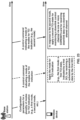
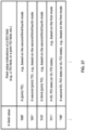
- the method includes receiving - by the wireless device from a base station - one or more radio resource control (RRC) messages indicating a transmission configuration indicator (TCI) indication type among a first TCI indication type and second TCI indication type, wherein: the first TCI indication type indicates one or more first TCI states are for downlink receptions via a cell and one or more second TCI states are for uplink transmissions via the cell, and the second TCI indication type indicates one or more third TCI states are for both downlink receptions and uplink transmissions via the cell.
- RRC radio resource control
- the method further includes receiving a first downlink control information (DCI) comprising a TCI field indicating a TCI state, of the one or more third TCI states, applicable to both uplink transmissions and downlink receptions; receiving - via the cell - downlink receptions based on the TCI state; and transmitting, via the cell, uplink transmissions based on the TCI state.
- DCI downlink control information
- a respective wireless device as well as related apparatuses, devices and methods are described.
- Embodiments may be configured to operate as needed.
- the disclosed mechanism may be performed when certain criteria are met, for example, in a wireless device, a base station, a radio environment, a network, a combination of the above, and/or the like.
- Example criteria may be based, at least in part, on for example, wireless device or network node configurations, traffic load, initial system set up, packet sizes, traffic characteristics, a combination of the above, and/or the like.
- various example embodiments may be applied. Therefore, it may be possible to implement example embodiments that selectively implement disclosed protocols.
- a and B are sets and every element of A is an element of B, A is called a subset of B.
- A is called a subset of B.
- possible subsets of B ⁇ cell1, cell2 ⁇ are: ⁇ cell1 ⁇ , ⁇ cell2 ⁇ , and ⁇ cell1, cell2 ⁇ .
- the phrase "based on” is indicative that the phrase following the term "based on” is an example of one of a multitude of suitable possibilities that may, or may not, be employed to one or more of the various embodiments.
- the phrase "in response to” is indicative that the phrase following the phrase “in response to” is an example of one of a multitude of suitable possibilities that may, or may not, be employed to one or more of the various embodiments.
- the phrase “depending on” is indicative that the phrase following the phrase “depending on” is an example of one of a multitude of suitable possibilities that may, or may not, be employed to one or more of the various embodiments.
- the phrase “employing/using” (or equally “employing/using at least”) is indicative that the phrase following the phrase “employing/using” is an example of one of a multitude of suitable possibilities that may, or may not, be employed to one or more of the various embodiments.
- the term configured may relate to the capacity of a device whether the device is in an operational or non-operational state.
- Configured may refer to specific settings in a device that effect the operational characteristics of the device whether the device is in an operational or non-operational state.
- the hardware, software, firmware, registers, memory values, and/or the like may be "configured” within a device, whether the device is in an operational or nonoperational state, to provide the device with specific characteristics.
- Terms such as "a control message to cause in a device” may mean that a control message has parameters that may be used to configure specific characteristics or may be used to implement certain actions in the device, whether the device is in an operational or non-operational state.
- parameters may comprise one or more information objects, and an information object may comprise one or more other objects.
- an information object may comprise one or more other objects.
- parameter (IE) N comprises parameter (IE) M
- parameter (IE) M comprises parameter (IE) K
- parameter (IE) K comprises parameter (information element) J.
- N comprises K
- N comprises J.
- one or more messages comprise a plurality of parameters
- modules may be implemented as modules.
- a module is defined here as an element that performs a defined function and has a defined interface to other elements.
- the modules described in this disclosure may be implemented in hardware, software in combination with hardware, firmware, wetware (e.g. hardware with a biological element) or a combination thereof, which may be behaviorally equivalent.
- modules may be implemented as a software routine written in a computer language configured to be executed by a hardware machine (such as C, C++, Fortran, Java, Basic, Matlab or the like) or a modeling/simulation program such as Simulink, Stateflow, GNU Script, or LabVIEWMathScript.
- modules may be possible to implement modules using physical hardware that incorporates discrete or programmable analog, digital and/or quantum hardware.
- programmable hardware comprise: computers, microcontrollers, microprocessors, application-specific integrated circuits (ASICs); field programmable gate arrays (FPGAs); and complex programmable logic devices (CPLDs).
- Computers, microcontrollers and microprocessors are programmed using languages such as assembly, C, C++ or the like.
- FPGAs, ASICs and CPLDs are often programmed using hardware description languages (HDL) such as VHSIC hardware description language (VHDL) or Verilog that configure connections between internal hardware modules with lesser functionality on a programmable device.
- HDL hardware description languages
- VHDL VHSIC hardware description language
- Verilog Verilog
- FIG. 1A illustrates an example of a mobile communication network 100 in which embodiments of the present disclosure may be implemented.
- the mobile communication network 100 may be, for example, a public land mobile network (PLMN) run by a network operator.
- PLMN public land mobile network
- the mobile communication network 100 includes a core network (CN) 102, a radio access network (RAN) 104, and a wireless device 106.
- CN core network
- RAN radio access network
- wireless device 106 wireless device
- the CN 102 may provide the wireless device 106 with an interface to one or more data networks (DNs), such as public DNs (e.g., the Internet), private DNs, and/or intra-operator DNs.
- DNs data networks
- the CN 102 may set up end-to-end connections between the wireless device 106 and the one or more DNs, authenticate the wireless device 106, and provide charging functionality.
- the AMF 158A may perform functions such as Non-Access Stratum (NAS) signaling termination, NAS signaling security, Access Stratum (AS) security control, inter-CN node signaling for mobility between 3GPP access networks, idle mode UE reachability (e.g., control and execution of paging retransmission), registration area management, intra-system and intersystem mobility support, access authentication, access authorization including checking of roaming rights, mobility management control (subscription and policies), network slicing support, and/or session management function (SMF) selection.
- NAS may refer to the functionality operating between a CN and a UE
- AS may refer to the functionality operating between the UE and a RAN.
- the 5G-CN 152 may include one or more additional network functions that are not shown in FIG. 1B for the sake of clarity.
- the 5G-CN 152 may include one or more of a Session Management Function (SMF), an NR Repository Function (NRF), a Policy Control Function (PCF), a Network Exposure Function (NEF), a Unified Data Management (UDM), an Application Function (AF), and/or an Authentication Server Function (AUSF).
- SMF Session Management Function
- NRF NR Repository Function
- PCF Policy Control Function
- NEF Network Exposure Function
- UDM Unified Data Management
- AF Application Function
- AUSF Authentication Server Function
- the NG-RAN 154 may connect the 5G-CN 152 to the UEs 156 through radio communications over the air interface.
- the NG-RAN 154 may include one or more gNBs, illustrated as gNB 160A and gNB 160B (collectively gNBs 160) and/or one or more ng-eNBs, illustrated as ng-eNB 162A and ng-eNB 162B (collectively ng-eNBs 162).
- the gNBs 160 and ng-eNBs 162 may be more generically referred to as base stations.
- the gNBs 160 and ng-eNBs 162 may include one or more sets of antennas for communicating with the UEs 156 over an air interface.
- one or more of the gNBs 160 and/or one or more of the ng-eNBs 162 may include three sets of antennas to respectively control three cells (or sectors). Together, the cells of the gNBs 160 and the ng-eNBs 162 may provide radio coverage to the UEs 156 over a wide geographic area to support UE mobility.
- the gNBs 160 and/or the ng-eNBs 162 may be connected to the 5G-CN 152 by means of an NG interface and to other base stations by an Xn interface.
- the NG and Xn interfaces may be established using direct physical connections and/or indirect connections over an underlying transport network, such as an internet protocol (IP) transport network.
- IP internet protocol
- the gNBs 160 and/or the ng-eNBs 162 may be connected to the UEs 156 by means of a Uu interface.
- gNB 160A may be connected to the UE 156A by means of a Uu interface.
- the NG, Xn, and Uu interfaces are associated with a protocol stack.
- the protocol stacks associated with the interfaces may be used by the network elements in FIG. 1B to exchange data and signaling messages and may include two planes: a user plane and a control plane.
- the user plane may handle data of interest to a user.
- the control plane may handle signaling messages of interest to the network elements.
- the gNBs 160 and/or the ng-eNBs 162 may be connected to one or more AMF/UPF functions of the 5G-CN 152, such as the AMF/UPF 158, by means of one or more NG interfaces.
- the gNB 160A may be connected to the UPF 158B of the AMF/UPF 158 by means of an NG-User plane (NG-U) interface.
- the NG-U interface may provide delivery (e.g., non-guaranteed delivery) of user plane PDUs between the gNB 160A and the UPF 158B.
- the gNB 160A may be connected to the AMF 158A by means of an NG-Control plane (NG-C) interface.
- the NG-C interface may provide, for example, NG interface management, UE context management, UE mobility management, transport of NAS messages, paging, PDU session management, and configuration transfer and/or warning message transmission.
- the gNBs 160 may provide NR user plane and control plane protocol terminations towards the UEs 156 over the Uu interface.
- the gNB 160A may provide NR user plane and control plane protocol terminations toward the UE 156A over a Uu interface associated with a first protocol stack.
- the ng-eNBs 162 may provide Evolved UMTS Terrestrial Radio Access (E-UTRA) user plane and control plane protocol terminations towards the UEs 156 over a Uu interface, where E-UTRA refers to the 3GPP 4G radio-access technology.
- E-UTRA refers to the 3GPP 4G radio-access technology.
- the ng-eNB 162B may provide E-UTRA user plane and control plane protocol terminations towards the UE 156B over a Uu interface associated with a second protocol stack.
- the 5G-CN 152 was described as being configured to handle NR and 4G radio accesses. It will be appreciated by one of ordinary skill in the art that it may be possible for NR to connect to a 4G core network in a mode known as "non-standalone operation.” In non-standalone operation, a 4G core network is used to provide (or at least support) control-plane functionality (e.g., initial access, mobility, and paging). Although only one AMF/UPF 158 is shown in FIG. 1B , one gNB or ng-eNB may be connected to multiple AMF/UPF nodes to provide redundancy and/or to load share across the multiple AMF/UPF nodes.
- an interface (e.g., Uu, Xn, and NG interfaces) between the network elements in FIG. 1B may be associated with a protocol stack that the network elements use to exchange data and signaling messages.
- a protocol stack may include two planes: a user plane and a control plane. The user plane may handle data of interest to a user, and the control plane may handle signaling messages of interest to the network elements.
- FIG. 2A and FIG. 2B respectively illustrate examples of NR user plane and NR control plane protocol stacks for the Uu interface that lies between a UE 210 and a gNB 220.
- the protocol stacks illustrated in FIG. 2A and FIG. 2B may be the same or similar to those used for the Uu interface between, for example, the UE 156A and the gNB 160A shown in FIG. 1B .
- FIG. 2A illustrates a NR user plane protocol stack comprising five layers implemented in the UE 210 and the gNB 220.
- PHYs physical layers
- PHYs 211 and 221 may provide transport services to the higher layers of the protocol stack and may correspond to layer 1 of the Open Systems Interconnection (OSI) model.
- the next four protocols above PHYs 211 and 221 comprise media access control layers (MACs) 212 and 222, radio link control layers (RLCs) 213 and 223, packet data convergence protocol layers (PDCPs) 214 and 224, and service data application protocol layers (SDAPs) 215 and 225. Together, these four protocols may make up layer 2, or the data link layer, of the OSI model.
- MACs media access control layers
- RLCs radio link control layers
- PDCPs packet data convergence protocol layers
- SDAPs service data application protocol layers
- FIG. 3 illustrates an example of services provided between protocol layers of the NR user plane protocol stack.
- the SDAPs 215 and 225 may perform QoS flow handling.
- the UE 210 may receive services through a PDU session, which may be a logical connection between the UE 210 and a DN.
- the PDU session may have one or more QoS flows.
- a UPF of a CN e.g., the UPF 158B
- the SDAPs 215 and 225 may perform mapping/de-mapping between the one or more QoS flows and one or more data radio bearers.
- the mapping/de-mapping between the QoS flows and the data radio bearers may be determined by the SDAP 225 at the gNB 220.
- the SDAP 215 at the UE 210 may be informed of the mapping between the QoS flows and the data radio bearers through reflective mapping or control signaling received from the gNB 220.
- the SDAP 225 at the gNB 220 may mark the downlink packets with a QoS flow indicator (QFI), which may be observed by the SDAP 215 at the UE 210 to determine the mapping/de-mapping between the QoS flows and the data radio bearers.
- QFI QoS flow indicator
- the PDCPs 214 and 224 may perform header compression/decompression to reduce the amount of data that needs to be transmitted over the air interface, ciphering/deciphering to prevent unauthorized decoding of data transmitted over the air interface, and integrity protection (to ensure control messages originate from intended sources.
- the PDCPs 214 and 224 may perform retransmissions of undelivered packets, in-sequence delivery and reordering of packets, and removal of packets received in duplicate due to, for example, an intra-gNB handover.
- the PDCPs 214 and 224 may perform packet duplication to improve the likelihood of the packet being received and, at the receiver, remove any duplicate packets. Packet duplication may be useful for services that require high reliability.
- PDCPs 214 and 224 may perform mapping/de-mapping between a split radio bearer and RLC channels in a dual connectivity scenario.
- Dual connectivity is a technique that allows a UE to connect to two cells or, more generally, two cell groups: a master cell group (MCG) and a secondary cell group (SCG).
- MCG master cell group
- SCG secondary cell group
- a split bearer is when a single radio bearer, such as one of the radio bearers provided by the PDCPs 214 and 224 as a service to the SDAPs 215 and 225, is handled by cell groups in dual connectivity.
- the PDCPs 214 and 224 may map/de-map the split radio bearer between RLC channels belonging to cell groups.
- the RLCs 213 and 223 may perform segmentation, retransmission through Automatic Repeat Request (ARQ), and removal of duplicate data units received from MACs 212 and 222, respectively.
- the RLCs 213 and 223 may support three transmission modes: transparent mode (TM); unacknowledged mode (UM); and acknowledged mode (AM). Based on the transmission mode an RLC is operating, the RLC may perform one or more of the noted functions.
- the RLC configuration may be per logical channel with no dependency on numerologies and/or Transmission Time Interval (TTI) durations. As shown in FIG. 3 , the RLCs 213 and 223 may provide RLC channels as a service to PDCPs 214 and 224, respectively.
- TTI Transmission Time Interval
- the MACs 212 and 222 may perform multiplexing/demultiplexing of logical channels and/or mapping between logical channels and transport channels.
- the multiplexing/demultiplexing may include multiplexing/demultiplexing of data units, belonging to the one or more logical channels, into/from Transport Blocks (TBs) delivered to/from the PHYs 211 and 221.
- the MAC 222 may be configured to perform scheduling, scheduling information reporting, and priority handling between UEs by means of dynamic scheduling. Scheduling may be performed in the gNB 220 (at the MAC 222) for downlink and uplink.
- the MACs 212 and 222 may be configured to perform error correction through Hybrid Automatic Repeat Request (HARQ) (e.g., one HARQ entity per carrier in case of Carrier Aggregation (CA)), priority handling between logical channels of the UE 210 by means of logical channel prioritization, and/or padding.
- HARQ Hybrid Automatic Repeat Request
- the MACs 212 and 222 may support one or more numerologies and/or transmission timings. In an example, mapping restrictions in a logical channel prioritization may control which numerology and/or transmission timing a logical channel may use.
- the MACs 212 and 222 may provide logical channels as a service to the RLCs 213 and 223.
- the PHYs 211 and 221 may perform mapping of transport channels to physical channels and digital and analog signal processing functions for sending and receiving information over the air interface. These digital and analog signal processing functions may include, for example, coding/decoding and modulation/demodulation.
- the PHYs 211 and 221 may perform multi-antenna mapping. As shown in FIG. 3 , the PHYs 211 and 221 may provide one or more transport channels as a service to the MACs 212 and 222.
- FIG. 4A illustrates an example downlink data flow through the NR user plane protocol stack.
- FIG. 4A illustrates a downlink data flow of three IP packets ( n, n+1, and m ) through the NR user plane protocol stack to generate two TBs at the gNB 220.
- An uplink data flow through the NR user plane protocol stack may be similar to the downlink data flow depicted in FIG. 4A .
- the downlink data flow of FIG. 4A begins when SDAP 225 receives the three IP packets from one or more QoS flows and maps the three packets to radio bearers.
- the SDAP 225 maps IP packets n and n+1 to a first radio bearer 402 and maps IP packet m to a second radio bearer 404.
- An SDAP header (labeled with an "H" in FIG. 4A ) is added to an IP packet.
- the data unit from/to a higher protocol layer is referred to as a service data unit (SDU) of the lower protocol layer and the data unit to/from a lower protocol layer is referred to as a protocol data unit (PDU) of the higher protocol layer.
- SDU service data unit
- PDU protocol data unit
- the data unit from the SDAP 225 is an SDU of lower protocol layer PDCP 224 and is a PDU of the SDAP 225.
- FIG. 4B illustrates an example format of a MAC subheader in a MAC PDU.
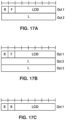
- the MAC subheader includes: an SDU length field for indicating the length (e.g., in bytes) of the MAC SDU to which the MAC subheader corresponds; a logical channel identifier (LCID) field for identifying the logical channel from which the MAC SDU originated to aid in the demultiplexing process; a flag (F) for indicating the size of the SDU length field; and a reserved bit (R) field for future use.
- SDU length field for indicating the length (e.g., in bytes) of the MAC SDU to which the MAC subheader corresponds
- LCID logical channel identifier
- F flag
- R reserved bit
- FIG. 4B further illustrates MAC control elements (CEs) inserted into the MAC PDU by a MAC, such as MAC 223 or MAC 222.
- a MAC such as MAC 223 or MAC 222.
- FIG. 4B illustrates two MAC CEs inserted into the MAC PDU.
- MAC CEs may be inserted at the beginning of a MAC PDU for downlink transmissions (as shown in FIG. 4B ) and at the end of a MAC PDU for uplink transmissions.
- MAC CEs may be used for in-band control signaling.
- Example MAC CEs include: scheduling-related MAC CEs, such as buffer status reports and power headroom reports; activation/deactivation MAC CEs, such as those for activation/deactivation of PDCP duplication detection, channel state information (CSI) reporting, sounding reference signal (SRS) transmission, and prior configured components; discontinuous reception (DRX) related MAC CEs; timing advance MAC CEs; and random access related MAC CEs.
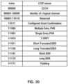
- a MAC CE may be preceded by a MAC subheader with a similar format as described for MAC SDUs and may be identified with a reserved value in the LCID field that indicates the type of control information included in the MAC CE.
- logical channels, transport channels, and physical channels are first described as well as a mapping between the channel types.
- One or more of the channels may be used to carry out functions associated with the NR control plane protocol stack described later below.
- FIG. 5A and FIG. 5B illustrate, for downlink and uplink respectively, a mapping between logical channels, transport channels, and physical channels.
- Information is passed through channels between the RLC, the MAC, and the PHY of the NR protocol stack.
- a logical channel may be used between the RLC and the MAC and may be classified as a control channel that carries control and configuration information in the NR control plane or as a traffic channel that carries data in the NR user plane.
- a logical channel may be classified as a dedicated logical channel that is dedicated to a specific UE or as a common logical channel that may be used by more than one UE.
- a logical channel may also be defined by the type of information it carries.
- the set of logical channels defined by NR include, for example:
- Transport channels are used between the MAC and PHY layers and may be defined by how the information they carry is transmitted over the air interface.
- the set of transport channels defined by NR include, for example:
- the PHY may use physical channels to pass information between processing levels of the PHY.
- a physical channel may have an associated set of time-frequency resources for carrying the information of one or more transport channels.
- the PHY may generate control information to support the low-level operation of the PHY and provide the control information to the lower levels of the PHY via physical control channels, known as L1/L2 control channels.
- the set of physical channels and physical control channels defined by NR include, for example:
- the physical layer Similar to the physical control channels, the physical layer generates physical signals to support the low-level operation of the physical layer.
- the physical layer signals defined by NR include: primary synchronization signals (PSS), secondary synchronization signals (SSS), channel state information reference signals (CSI-RS), demodulation reference signals (DMRS), sounding reference signals (SRS), and phase-tracking reference signals (PT-RS). These physical layer signals will be described in greater detail below.
- FIG. 2B illustrates an example NR control plane protocol stack.
- the NR control plane protocol stack may use the same/similar first four protocol layers as the example NR user plane protocol stack. These four protocol layers include the PHYs 211 and 221, the MACs 212 and 222, the RLCs 213 and 223, and the PDCPs 214 and 224.
- the NR control plane stack has radio resource controls (RRCs) 216 and 226 and NAS protocols 217 and 237 at the top of the NR control plane protocol stack.
- RRCs radio resource controls
- the NAS protocols 217 and 237 may provide control plane functionality between the UE 210 and the AMF 230 (e.g., the AMF 158A) or, more generally, between the UE 210 and the CN.
- the NAS protocols 217 and 237 may provide control plane functionality between the UE 210 and the AMF 230 via signaling messages, referred to as NAS messages. There is no direct path between the UE 210 and the AMF 230 through which the NAS messages can be transported.
- the NAS messages may be transported using the AS of the Uu and NG interfaces.
- NAS protocols 217 and 237 may provide control plane functionality such as authentication, security, connection setup, mobility management, and session management.
- the RRCs 216 and 226 may provide control plane functionality between the UE 210 and the gNB 220 or, more generally, between the UE 210 and the RAN.
- the RRCs 216 and 226 may provide control plane functionality between the UE 210 and the gNB 220 via signaling messages, referred to as RRC messages.
- RRC messages may be transmitted between the UE 210 and the RAN using signaling radio bearers and the same/similar PDCP, RLC, MAC, and PHY protocol layers.
- the MAC may multiplex control-plane and user-plane data into the same transport block (TB).
- the RRCs 216 and 226 may provide control plane functionality such as: broadcast of system information related to AS and NAS; paging initiated by the CN or the RAN; establishment, maintenance and release of an RRC connection between the UE 210 and the RAN; security functions including key management; establishment, configuration, maintenance and release of signaling radio bearers and data radio bearers; mobility functions; QoS management functions; the UE measurement reporting and control of the reporting; detection of and recovery from radio link failure (RLF); and/or NAS message transfer.
- RRCs 216 and 226 may establish an RRC context, which may involve configuring parameters for communication between the UE 210 and the RAN.
- FIG. 6 is an example diagram showing RRC state transitions of a UE.
- the UE may be the same or similar to the wireless device 106 depicted in FIG. 1A , the UE 210 depicted in FIG. 2A and FIG. 2B , or any other wireless device described in the present disclosure.
- a UE may be in at least one of three RRC states: RRC connected 602 (e.g., RRC_CONNECTED), RRC idle 604 (e.g., RRC_IDLE), and RRC inactive 606 (e.g., RRC_INACTIVE).
- RRC connected 602 e.g., RRC_CONNECTED
- RRC idle 604 e.g., RRC_IDLE
- RRC inactive 606 e.g., RRC_INACTIVE
- the UE has an established RRC context and may have at least one RRC connection with a base station.
- the base station may be similar to one of the one or more base stations included in the RAN 104 depicted in FIG. 1A , one of the gNBs 160 or ng-eNBs 162 depicted in FIG. 1B , the gNB 220 depicted in FIG. 2A and FIG. 2B , or any other base station described in the present disclosure.
- the base station with which the UE is connected may have the RRC context for the UE.
- the RRC context referred to as the UE context, may comprise parameters for communication between the UE and the base station.
- These parameters may include, for example: one or more AS contexts; one or more radio link configuration parameters; bearer configuration information (e.g., relating to a data radio bearer, signaling radio bearer, logical channel, QoS flow, and/or PDU session); security information; and/or PHY, MAC, RLC, PDCP, and/or SDAP layer configuration information.
- bearer configuration information e.g., relating to a data radio bearer, signaling radio bearer, logical channel, QoS flow, and/or PDU session
- security information e.g., relating to a data radio bearer, signaling radio bearer, logical channel, QoS flow, and/or PDU session
- PHY e.g., MAC, RLC, PDCP, and/or SDAP layer configuration information
- the RAN e.g., the RAN 104 or the NG-RAN 154
- the UE may measure the signal levels (e.g., reference signal levels) from a serving cell
- the UE's serving base station may request a handover to a cell of one of the neighboring base stations based on the reported measurements.
- the RRC state may transition from RRC connected 602 to RRC idle 604 through a connection release procedure 608 or to RRC inactive 606 through a connection inactivation procedure 610.
- RRC idle 604 an RRC context may not be established for the UE.
- the UE may not have an RRC connection with the base station.
- the UE may be in a sleep state for the majority of the time (e.g., to conserve battery power).
- the UE may wake up periodically (e.g., once in every discontinuous reception cycle) to monitor for paging messages from the RAN.
- Mobility of the UE may be managed by the UE through a procedure known as cell reselection.
- the RRC state may transition from RRC idle 604 to RRC connected 602 through a connection establishment procedure 612, which may involve a random access procedure as discussed in greater detail below.
- a base station may configure a UE with one or more control resource sets (CORESETs) for at least one search space.
- CORESETs control resource sets
- a search space is a set of locations in the time and frequency domains where the UE may find control information.
- the search space may be a UE-specific search space or a common search space (potentially usable by a plurality of UEs).
- a base station may configure a UE with a common search space, on a PCell or on a primary secondary cell (PSCell), in an active downlink BWP.
- CA carrier aggregation
- the aggregated carriers in CA may be referred to as component carriers (CCs).
- CCs component carriers
- the CCs may have three configurations in the frequency domain.
- up to 32 CCs may be aggregated.
- the aggregated CCs may have the same or different bandwidths, subcarrier spacing, and/or duplexing schemes (TDD or FDD).
- a serving cell for a UE using CA may have a downlink CC.
- one or more uplink CCs may be optionally configured for a serving cell.
- the ability to aggregate more downlink carriers than uplink carriers may be useful, for example, when the UE has more data traffic in the downlink than in the uplink.
- one of the aggregated cells for a UE may be referred to as a primary cell (PCell).
- the PCell may be the serving cell that the UE initially connects to at RRC connection establishment, reestablishment, and/or handover.
- the PCell may provide the UE with NAS mobility information and the security input.
- UEs may have different PCells.
- the carrier corresponding to the PCell may be referred to as the downlink primary CC (DL PCC).
- the carrier corresponding to the PCell may be referred to as the uplink primary CC (UL PCC).
- SCells secondary cells
- the SCells may be configured after the PCell is configured for the UE.
- an SCell may be configured through an RRC Connection Reconfiguration procedure.
- the carrier corresponding to an SCell may be referred to as a downlink secondary CC (DL SCC).
- DL SCC downlink secondary CC
- UL SCC uplink secondary CC
- Configured SCells for a UE may be activated and deactivated based on, for example, traffic and channel conditions. Deactivation of an SCell may mean that PDCCH and PDSCH reception on the SCell is stopped and PUSCH, SRS, and CQI transmissions on the SCell are stopped. Configured SCells may be activated and deactivated using a MAC CE with respect to FIG. 4B . For example, a MAC CE may use a bitmap (e.g., one bit per SCell) to indicate which SCells (e.g., in a subset of configured SCells) for the UE are activated or deactivated. Configured SCells may be deactivated in response to an expiration of an SCell deactivation timer (e.g., one SCell deactivation timer per SCell).
- an SCell deactivation timer e.g., one SCell deactivation timer per SCell.
- Downlink control information such as scheduling assignments and scheduling grants, for a cell may be transmitted on the cell corresponding to the assignments and grants, which is known as self-scheduling.
- the DCI for the cell may be transmitted on another cell, which is known as cross-carrier scheduling.
- Uplink control information e.g., HARQ acknowledgments and channel state feedback, such as CQI, PMI, and/or RI
- CQI, PMI, and/or RI channel state feedback
- FIG. 10B illustrates an example of how aggregated cells may be configured into one or more PUCCH groups.
- a PUCCH group 1010 and a PUCCH group 1050 may include one or more downlink CCs, respectively.
- the PUCCH group 1010 includes three downlink CCs: a PCell 1011, an SCell 1012, and an SCell 1013.
- the PUCCH group 1050 includes three downlink CCs in the present example: a PCell 1051, an SCell 1052, and an SCell 1053.
- One or more uplink CCs may be configured as a PCell 1021, an SCell 1022, and an SCell 1023.
- One or more other uplink CCs may be configured as a primary Scell (PSCell) 1061, an SCell 1062, and an SCell 1063.
- Uplink control information (UCI) related to the downlink CCs of the PUCCH group 1010 shown as UCI 1031, UCI 1032, and UCI 1033, may be transmitted in the uplink of the PCell 1021.
- Uplink control information (UCI) related to the downlink CCs of the PUCCH group 1050, shown as UCI 1071, UCI 1072, and UCI 1073, may be transmitted in the uplink of the PSCell 1061.
- a cell comprising a downlink carrier and optionally an uplink carrier, may be assigned with a physical cell ID and a cell index.
- the physical cell ID or the cell index may identify a downlink carrier and/or an uplink carrier of the cell, for example, depending on the context in which the physical cell ID is used.
- a physical cell ID may be determined using a synchronization signal transmitted on a downlink component carrier.
- a cell index may be determined using RRC messages.
- a physical cell ID may be referred to as a carrier ID
- a cell index may be referred to as a carrier index.
- the disclosure may mean the first physical cell ID is for a cell comprising the first downlink carrier.
- the same/similar concept may apply to, for example, a carrier activation.
- the disclosure indicates that a first carrier is activated
- the specification may mean that a cell comprising the first carrier is activated.
- a multi-carrier nature of a PHY may be exposed to a MAC.
- a HARQ entity may operate on a serving cell.
- a transport block may be generated per assignment/grant per serving cell.
- a transport block and potential HARQ retransmissions of the transport block may be mapped to a serving cell.
- a base station may transmit (e.g., unicast, multicast, and/or broadcast) one or more Reference Signals (RSs) to a UE (e.g., PSS, SSS, CSI-RS, DMRS, and/or PT-RS, as shown in FIG. 5A ).
- RSs Reference Signals
- the UE may transmit one or more RSs to the base station (e.g., DMRS, PT-RS, and/or SRS, as shown in FIG. 5B ).
- the PSS and the SSS may be transmitted by the base station and used by the UE to synchronize the UE to the base station.
- the PSS and the SSS may be provided in a synchronization signal (SS) / physical broadcast channel (PBCH) block that includes the PSS, the SSS, and the PBCH.
- the base station may periodically transmit a burst of SS/PBCH blocks.
- FIG. 11A illustrates an example of an SS/PBCH block's structure and location.
- a burst of SS/PBCH blocks may include one or more SS/PBCH blocks (e.g., 4 SS/PBCH blocks, as shown in FIG. 11A ). Bursts may be transmitted periodically (e.g., every 2 frames or 20 ms). A burst may be restricted to a half-frame (e.g., a first half-frame having a duration of 5 ms). It will be understood that FIG.
- 11A is an example, and that these parameters (number of SS/PBCH blocks per burst, periodicity of bursts, position of burst within the frame) may be configured based on, for example: a carrier frequency of a cell in which the SS/PBCH block is transmitted; a numerology or subcarrier spacing of the cell; a configuration by the network (e.g., using RRC signaling); or any other suitable factor.
- the UE may assume a subcarrier spacing for the SS/PBCH block based on the carrier frequency being monitored, unless the radio network configured the UE to assume a different subcarrier spacing.
- the SS/PBCH block may span one or more OFDM symbols in the time domain (e.g., 4 OFDM symbols, as shown in the example of FIG. 11A ) and may span one or more subcarriers in the frequency domain (e.g., 240 contiguous subcarriers).
- the PSS, the SSS, and the PBCH may have a common center frequency.
- the PSS may be transmitted first and may span, for example, 1 OFDM symbol and 127 subcarriers.
- the SSS may be transmitted after the PSS (e.g., two symbols later) and may span 1 OFDM symbol and 127 subcarriers.
- the PBCH may be transmitted after the PSS (e.g., across the next 3 OFDM symbols) and may span 240 subcarriers.
- the location of the SS/PBCH block in the time and frequency domains may not be known to the UE (e.g., if the UE is searching for the cell).
- the UE may monitor a carrier for the PSS. For example, the UE may monitor a frequency location within the carrier. If the PSS is not found after a certain duration (e.g., 20 ms), the UE may search for the PSS at a different frequency location within the carrier, as indicated by a synchronization raster. If the PSS is found at a location in the time and frequency domains, the UE may determine, based on a known structure of the SS/PBCH block, the locations of the SSS and the PBCH, respectively.
- the SS/PBCH block may be a cell-defining SS block (CD-SSB).
- a primary cell may be associated with a CD-SSB.
- the CD-SSB may be located on a synchronization raster.
- a cell selection/search and/or reselection may be based on the CD-SSB.
- the SS/PBCH block may be used by the UE to determine one or more parameters of the cell. For example, the UE may determine a physical cell identifier (PCI) of the cell based on the sequences of the PSS and the SSS, respectively. The UE may determine a location of a frame boundary of the cell based on the location of the SS/PBCH block. For example, the SS/PBCH block may indicate that it has been transmitted in accordance with a transmission pattern, wherein a SS/PBCH block in the transmission pattern is a known distance from the frame boundary.
- PCI physical cell identifier
- the PBCH may use a QPSK modulation and may use forward error correction (FEC).
- FEC forward error correction
- the FEC may use polar coding.
- One or more symbols spanned by the PBCH may carry one or more DMRSs for demodulation of the PBCH.
- the PBCH may include an indication of a current system frame number (SFN) of the cell and/or a SS/PBCH block timing index. These parameters may facilitate time synchronization of the UE to the base station.
- the PBCH may include a master information block (MIB) used to provide the UE with one or more parameters.
- the MIB may be used by the UE to locate remaining minimum system information (RMSI) associated with the cell.
- the RMSI may include a System Information Block Type 1 (SIB1).
- the SIB1 may contain information needed by the UE to access the cell.
- the UE may use one or more parameters of the MIB to monitor PDCCH, which may be used to schedule PDSCH.
- the PDSCH may include the SIB1.
- the SIB1 may be decoded using parameters provided in the MIB.
- the PBCH may indicate an absence of SIB1. Based on the PBCH indicating the absence of SIB1, the UE may be pointed to a frequency. The UE may search for an SS/PBCH block at the frequency to which the UE is pointed.
- the UE may assume that one or more SS/PBCH blocks transmitted with a same SS/PBCH block index are quasi co-located (QCLed) (e.g., having the same/similar Doppler spread, Doppler shift, average gain, average delay, and/or spatial Rx parameters).
- QCL quasi co-located
- SS/PBCH blocks may be transmitted in spatial directions (e.g., using different beams that span a coverage area of the cell).
- a first SS/PBCH block may be transmitted in a first spatial direction using a first beam
- a second SS/PBCH block may be transmitted in a second spatial direction using a second beam.
- a base station may transmit a plurality of SS/PBCH blocks.
- a first PCI of a first SS/PBCH block of the plurality of SS/PBCH blocks may be different from a second PCI of a second SS/PBCH block of the plurality of SS/PBCH blocks.
- the PCIs of SS/PBCH blocks transmitted in different frequency locations may be different or the same.
- the CSI-RS may be transmitted by the base station and used by the UE to acquire channel state information (CSI).
- the base station may configure the UE with one or more CSI-RSs for channel estimation or any other suitable purpose.
- the base station may configure a UE with one or more of the same/similar CSI-RSs.
- the UE may measure the one or more CSI-RSs.
- the UE may estimate a downlink channel state and/or generate a CSI report based on the measuring of the one or more downlink CSI-RSs.
- the UE may provide the CSI report to the base station.
- the base station may use feedback provided by the UE (e.g., the estimated downlink channel state) to perform link adaptation.
- the base station may semi-statically configure the UE with one or more CSI-RS resource sets.
- a CSI-RS resource may be associated with a location in the time and frequency domains and a periodicity.
- the base station may selectively activate and/or deactivate a CSI-RS resource.
- the base station may indicate to the UE that a CSI-RS resource in the CSI-RS resource set is activated and/or deactivated.
- the base station may configure the UE to report CSI measurements.
- the base station may configure the UE to provide CSI reports periodically, aperiodically, or semi-persistently.
- periodic CSI reporting the UE may be configured with a timing and/or periodicity of a plurality of CSI reports.
- the base station may request a CSI report.
- the base station may command the UE to measure a configured CSI-RS resource and provide a CSI report relating to the measurements.
- the base station may configure the UE to transmit periodically, and selectively activate or deactivate the periodic reporting.
- the base station may configure the UE with a CSI-RS resource set and CSI reports using RRC signaling.
- the CSI-RS configuration may comprise one or more parameters indicating, for example, up to 32 antenna ports.
- the UE may be configured to employ the same OFDM symbols for a downlink CSI-RS and a control resource set (CORESET) when the downlink CSI-RS and CORESET are spatially QCLed and resource elements associated with the downlink CSI-RS are outside of the physical resource blocks (PRBs) configured for the CORESET.
- the UE may be configured to employ the same OFDM symbols for downlink CSI-RS and SS/PBCH blocks when the downlink CSI-RS and SS/PBCH blocks are spatially QCLed and resource elements associated with the downlink CSI-RS are outside of PRBs configured for the SS/PBCH blocks.
- Downlink DMRSs may be transmitted by a base station and used by a UE for channel estimation.
- the downlink DMRS may be used for coherent demodulation of one or more downlink physical channels (e.g., PDSCH).
- An NR network may support one or more variable and/or configurable DMRS patterns for data demodulation.
- At least one downlink DMRS configuration may support a front-loaded DMRS pattern.
- a front-loaded DMRS may be mapped over one or more OFDM symbols (e.g., one or two adjacent OFDM symbols).
- a base station may semi-statically configure the UE with a number (e.g. a maximum number) of front-loaded DMRS symbols for PDSCH.
- a DMRS configuration may support one or more DMRS ports.
- a DMRS configuration may support up to eight orthogonal downlink DMRS ports per UE.
- a DMRS configuration may support up to 4 orthogonal downlink DMRS ports per UE.
- a radio network may support (e.g., at least for CP-OFDM) a common DMRS structure for downlink and uplink, wherein a DMRS location, a DMRS pattern, and/or a scrambling sequence may be the same or different.
- the base station may transmit a downlink DMRS and a corresponding PDSCH using the same precoding matrix.
- the UE may use the one or more downlink DMRSs for coherent demodulation/channel estimation of the PDSCH.
- a transmitter may use a precoder matrices for a part of a transmission bandwidth.
- the transmitter may use a first precoder matrix for a first bandwidth and a second precoder matrix for a second bandwidth.
- the first precoder matrix and the second precoder matrix may be different based on the first bandwidth being different from the second bandwidth.
- the UE may assume that a same precoding matrix is used across a set of PRBs.
- the set of PRBs may be denoted as a precoding resource block group (PRG).
- PRG precoding resource block group
- a PDSCH may comprise one or more layers.
- the UE may assume that at least one symbol with DMRS is present on a layer of the one or more layers of the PDSCH.
- a higher layer may configure up to 3 DMRSs for the PDSCH.
- Downlink PT-RS may be transmitted by a base station and used by a UE for phase-noise compensation. Whether a downlink PT-RS is present or not may depend on an RRC configuration. The presence and/or pattern of the downlink PT-RS may be configured on a UE-specific basis using a combination of RRC signaling and/or an association with one or more parameters employed for other purposes (e.g., modulation and coding scheme (MCS)), which may be indicated by DCI. When configured, a dynamic presence of a downlink PT-RS may be associated with one or more DCI parameters comprising at least MCS.
- An NR network may support a plurality of PT-RS densities defined in the time and/or frequency domains.
- a frequency domain density may be associated with at least one configuration of a scheduled bandwidth.
- the UE may assume a same precoding for a DMRS port and a PT-RS port.
- a number of PT-RS ports may be fewer than a number of DMRS ports in a scheduled resource.
- Downlink PT-RS may be confined in the scheduled time/frequency duration for the UE.
- Downlink PT-RS may be transmitted on symbols to facilitate phase tracking at the receiver.
- the UE may transmit an uplink DMRS to a base station for channel estimation.
- the base station may use the uplink DMRS for coherent demodulation of one or more uplink physical channels.
- the UE may transmit an uplink DMRS with a PUSCH and/or a PUCCH.
- the uplink DM-RS may span a range of frequencies that is similar to a range of frequencies associated with the corresponding physical channel.
- the base station may configure the UE with one or more uplink DMRS configurations. At least one DMRS configuration may support a front-loaded DMRS pattern.
- the front-loaded DMRS may be mapped over one or more OFDM symbols (e.g., one or two adjacent OFDM symbols).
- One or more uplink DMRSs may be configured to transmit at one or more symbols of a PUSCH and/or a PUCCH.
- the base station may semi-statically configure the UE with a number (e.g. maximum number) of front-loaded DMRS symbols for the PUSCH and/or the PUCCH, which the UE may use to schedule a single-symbol DMRS and/or a double-symbol DMRS.
- An NR network may support (e.g., for cyclic prefix orthogonal frequency division multiplexing (CP-OFDM)) a common DMRS structure for downlink and uplink, wherein a DMRS location, a DMRS pattern, and/or a scrambling sequence for the DMRS may be the same or different.
- CP-OFDM cyclic prefix orthogonal frequency division multiplexing
- a PUSCH may comprise one or more layers, and the UE may transmit at least one symbol with DMRS present on a layer of the one or more layers of the PUSCH.
- a higher layer may configure up to three DMRSs for the PUSCH.
- an SRS resource in a SRS resource set of the one or more SRS resource sets may be transmitted at a time instant (e.g., simultaneously).
- the UE may transmit one or more SRS resources in SRS resource sets.
- An NR network may support aperiodic, periodic and/or semi-persistent SRS transmissions.
- the UE may transmit SRS resources based on one or more trigger types, wherein the one or more trigger types may comprise higher layer signaling (e.g., RRC) and/or one or more DCI formats.
- At least one DCI format may be employed for the UE to select at least one of one or more configured SRS resource sets.
- An SRS trigger type 0 may refer to an SRS triggered based on a higher layer signaling.
- An SRS trigger type 1 may refer to an SRS triggered based on one or more DCI formats.
- the UE when PUSCH and SRS are transmitted in a same slot, the UE may be configured to transmit SRS after a transmission of a PUSCH and a corresponding uplink DMRS.
- the base station may semi-statically configure the UE with one or more SRS configuration parameters indicating at least one of following: a SRS resource configuration identifier; a number of SRS ports; time domain behavior of an SRS resource configuration (e.g., an indication of periodic, semi-persistent, or aperiodic SRS); slot, mini-slot, and/or subframe level periodicity; offset for a periodic and/or an aperiodic SRS resource; a number of OFDM symbols in an SRS resource; a starting OFDM symbol of an SRS resource; an SRS bandwidth; a frequency hopping bandwidth; a cyclic shift; and/or an SRS sequence ID.
- SRS resource configuration identifier e.g., an indication of periodic, semi-persistent, or aperiodic SRS
- slot, mini-slot, and/or subframe level periodicity e.g., an indication of periodic, semi-persistent, or aperiodic SRS
- An antenna port is defined such that the channel over which a symbol on the antenna port is conveyed can be inferred from the channel over which another symbol on the same antenna port is conveyed. If a first symbol and a second symbol are transmitted on the same antenna port, the receiver may infer the channel (e.g., fading gain, multipath delay, and/or the like) for conveying the second symbol on the antenna port, from the channel for conveying the first symbol on the antenna port.
- a first antenna port and a second antenna port may be referred to as quasi co-located (QCLed) if one or more large-scale properties of the channel over which a first symbol on the first antenna port is conveyed may be inferred from the channel over which a second symbol on a second antenna port is conveyed.
- the one or more large-scale properties may comprise at least one of: a delay spread; a Doppler spread; a Doppler shift; an average gain; an average delay; and/or spatial Receiving (Rx) parameters.
- Beam management may comprise beam measurement, beam selection, and beam indication.
- a beam may be associated with one or more reference signals.
- a beam may be identified by one or more beamformed reference signals.
- the UE may perform downlink beam measurement based on downlink reference signals (e.g., a channel state information reference signal (CSI-RS)) and generate a beam measurement report.
- CSI-RS channel state information reference signal
- the UE may perform the downlink beam measurement procedure after an RRC connection is set up with a base station.
- FIG. 11B illustrates an example of channel state information reference signals (CSI-RSs) that are mapped in the time and frequency domains.
- CSI-RSs channel state information reference signals
- a square shown in FIG. 11B may span a resource block (RB) within a bandwidth of a cell.
- a base station may transmit one or more RRC messages comprising CSI-RS resource configuration parameters indicating one or more CSI-RSs.
- One or more of the following parameters may be configured by higher layer signaling (e.g., RRC and/or MAC signaling) for a CSI-RS resource configuration: a CSI-RS resource configuration identity, a number of CSI-RS ports, a CSI-RS configuration (e.g., symbol and resource element (RE) locations in a subframe), a CSI-RS subframe configuration (e.g., subframe location, offset, and periodicity in a radio frame), a CSI-RS power parameter, a CSI-RS sequence parameter, a code division multiplexing (CDM) type parameter, a frequency density, a transmission comb, quasi co-location (QCL) parameters (e.g., QCL-scramblingidentity, crs-portscount, mbsfn-subframeconfiglist, csi-rs-configZPid, qcl-csi-rs-configNZPid), and/or other radio resource parameters.
- the three beams illustrated in FIG. 11B may be configured for a UE in a UE-specific configuration. Three beams are illustrated in FIG. 11B (beam #1, beam #2, and beam #3), more or fewer beams may be configured.
- Beam #1 may be allocated with CSI-RS 1101 that may be transmitted in one or more subcarriers in an RB of a first symbol.
- Beam #2 may be allocated with CSI-RS 1102 that may be transmitted in one or more subcarriers in an RB of a second symbol.
- Beam #3 may be allocated with CSI-RS 1103 that may be transmitted in one or more subcarriers in an RB of a third symbol.
- a base station may use other subcarriers in a same RB (for example, those that are not used to transmit CSI-RS 1101) to transmit another CSI-RS associated with a beam for another UE.
- FDM frequency division multiplexing
- TDM time domain multiplexing
- CSI-RSs such as those illustrated in FIG. 11B (e.g., CSI-RS 1101, 1102, 1103) may be transmitted by the base station and used by the UE for one or more measurements.
- the UE may measure a reference signal received power (RSRP) of configured CSI-RS resources.
- the base station may configure the UE with a reporting configuration and the UE may report the RSRP measurements to a network (for example, via one or more base stations) based on the reporting configuration.
- the base station may determine, based on the reported measurement results, one or more transmission configuration indication (TCI) states comprising a number of reference signals.
- TCI transmission configuration indication
- the base station may indicate one or more TCI states to the UE (e.g., via RRC signaling, a MAC CE, and/or a DCI).
- the UE may receive a downlink transmission with a receive (Rx) beam determined based on the one or more TCI states.
- the UE may or may not have a capability of beam correspondence. If the UE has the capability of beam correspondence, the UE may determine a spatial domain filter of a transmit (Tx) beam based on a spatial domain filter of the corresponding Rx beam. If the UE does not have the capability of beam correspondence, the UE may perform an uplink beam selection procedure to determine the spatial domain filter of the Tx beam.
- the UE may perform the uplink beam selection procedure based on one or more sounding reference signal (SRS) resources configured to the UE by the base station.
- the base station may select and indicate uplink beams for the UE based on measurements of the one or more SRS resources transmitted by the UE.
- SRS sounding reference signal
- a UE may assess (e.g., measure) a channel quality of one or more beam pair links, a beam pair link comprising a transmitting beam transmitted by a base station and a receiving beam received by the UE. Based on the assessment, the UE may transmit a beam measurement report indicating one or more beam pair quality parameters comprising, e.g., one or more beam identifications (e.g., a beam index, a reference signal index, or the like), RSRP, a precoding matrix indicator (PMI), a channel quality indicator (CQI), and/or a rank indicator (RI).
- beam identifications e.g., a beam index, a reference signal index, or the like
- PMI precoding matrix indicator
- CQI channel quality indicator
- RI rank indicator
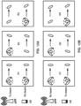
- FIG. 12A illustrates examples of three downlink beam management procedures: P1, P2, and P3.
- Procedure P1 may enable a UE measurement on transmit (Tx) beams of a transmission reception point (TRP) (or multiple TRPs), e.g., to support a selection of one or more base station Tx beams and/or UE Rx beams (shown as ovals in the top row and bottom row, respectively, of P1).
- Beamforming at a TRP may comprise a Tx beam sweep for a set of beams (shown, in the top rows of P1 and P2, as ovals rotated in a counter-clockwise direction indicated by the dashed arrow).
- Beamforming at a UE may comprise an Rx beam sweep for a set of beams (shown, in the bottom rows of P1 and P3, as ovals rotated in a clockwise direction indicated by the dashed arrow).
- Procedure P2 may be used to enable a UE measurement on Tx beams of a TRP (shown, in the top row of P2, as ovals rotated in a counter-clockwise direction indicated by the dashed arrow).
- the UE and/or the base station may perform procedure P2 using a smaller set of beams than is used in procedure P1, or using narrower beams than the beams used in procedure P1. This may be referred to as beam refinement.
- the UE may perform procedure P3 for Rx beam determination by using the same Tx beam at the base station and sweeping an Rx beam at the UE.
- the RS resource and the one or more DMRSs of the channel may be QCLed when the channel characteristics (e.g., Doppler shift, Doppler spread, average delay, delay spread, spatial Rx parameter, fading, and/or the like) from a transmission via the RS resource to the UE are similar or the same as the channel characteristics from a transmission via the channel to the UE.
- the channel characteristics e.g., Doppler shift, Doppler spread, average delay, delay spread, spatial Rx parameter, fading, and/or the like
- a network e.g., a gNB and/or an ng-eNB of a network
- the UE may initiate a random access procedure.
- a UE in an RRC_IDLE state and/or an RRC_INACTIVE state may initiate the random access procedure to request a connection setup to a network.
- the UE may initiate the random access procedure from an RRC_CONNECTED state.
- the UE may initiate the random access procedure to request uplink resources (e.g., for uplink transmission of an SR when there is no PUCCH resource available) and/or acquire uplink timing (e.g., when uplink synchronization status is non-synchronized).
- the UE may initiate the random access procedure to request one or more system information blocks (SIBs) (e.g., other system information such as SIB2, SIB3, and/or the like).
- SIBs system information blocks
- the UE may initiate the random access procedure for a beam failure recovery request.
- a network may initiate a random access procedure for a handover and/or for establishing time alignment for an SCell addition.
- FIG. 13A illustrates a four-step contention-based random access procedure.
- a base station may transmit a configuration message 1310 to the UE.
- the procedure illustrated in FIG. 13A comprises transmission of four messages: a Msg 1 1311, a Msg 2 1312, a Msg 3 1313, and a Msg 4 1314.
- the Msg 1 1311 may include and/or be referred to as a preamble (or a random access preamble).
- the Msg 2 1312 may include and/or be referred to as a random access response (RAR).
- RAR random access response
- the configuration message 1310 may be transmitted, for example, using one or more RRC messages.
- the one or more RRC messages may indicate one or more random access channel (RACH) parameters to the UE.
- the one or more RACH parameters may comprise at least one of following: general parameters for one or more random access procedures (e.g., RACH-configGeneral); cell-specific parameters (e.g., RACH-ConfigCommon); and/or dedicated parameters (e.g., RACH-configDedicated).
- the base station may broadcast or multicast the one or more RRC messages to one or more UEs.
- the one or more RRC messages may be UE-specific (e.g., dedicated RRC messages transmitted to a UE in an RRC_CONNECTED state and/or in an RRC_INACTIVE state).
- the UE may determine, based on the one or more RACH parameters, a time-frequency resource and/or an uplink transmit power for transmission of the Msg 1 1311 and/or the Msg 3 1313. Based on the one or more RACH parameters, the UE may determine a reception timing and a downlink channel for receiving the Msg 2 1312 and the Msg 4 1314.
- the UE may determine the preamble based on the one or more RACH parameters provided in the configuration message 1310. For example, the UE may determine the preamble based on a pathloss measurement, an RSRP measurement, and/or a size of the Msg 3 1313.
- the one or more RACH parameters may indicate: a preamble format; a maximum number of preamble transmissions; and/or one or more thresholds for determining one or more preamble groups (e.g., group A and group B).
- a base station may use the one or more RACH parameters to configure the UE with an association between one or more preambles and one or more reference signals (e.g., SSBs and/or CSI-RSs).
- the UE may determine the preamble to include in Msg 1 1311 based on the association.
- the Msg 1 1311 may be transmitted to the base station via one or more PRACH occasions.
- the UE may use one or more reference signals (e.g., SSBs and/or CSI-RSs) for selection of the preamble and for determining of the PRACH occasion.
- One or more RACH parameters e.g., ra-ssb-OccasionMskIndex and/or ra-OccasionList
- ra-ssb-OccasionMskIndex and/or ra-OccasionList may indicate an association between the PRACH occasions and the one or more reference signals.
- the UE may perform a preamble retransmission if no response is received following a preamble transmission.
- the UE may increase an uplink transmit power for the preamble retransmission.
- the UE may select an initial preamble transmit power based on a pathloss measurement and/or a target received preamble power configured by the network.
- the UE may determine to retransmit a preamble and may ramp up the uplink transmit power.
- the UE may receive one or more RACH parameters (e.g., PREAMBLE_POWER_RAMPING_STEP) indicating a ramping step for the preamble retransmission.
- the ramping step may be an amount of incremental increase in uplink transmit power for a retransmission.
- the UE may ramp up the uplink transmit power if the UE determines a reference signal (e.g., SSB and/or CSI-RS) that is the same as a previous preamble transmission.
- the UE may count a number of preamble transmissions and/or retransmissions (e.g., PREAMBLE_TRANSMISSION_COUNTER).
- the UE may determine that a random access procedure completed unsuccessfully, for example, if the number of preamble transmissions exceeds a threshold configured by the one or more RACH parameters (e.g., preambleTransMax).
- the Msg 2 1312 received by the UE may include an RAR.
- the Msg 2 1312 may include multiple RARs corresponding to multiple UEs.
- the Msg 2 1312 may be received after or in response to the transmitting of the Msg 1 1311.
- the Msg 2 1312 may be scheduled on the DL-SCH and indicated on a PDCCH using a random access RNTI (RA-RNTI).
- RA-RNTI random access RNTI
- the Msg 2 1312 may include a time-alignment command that may be used by the UE to adjust the UE's transmission timing, a scheduling grant for transmission of the Msg 3 1313, and/or a Temporary Cell RNTI (TC-RNTI).
- TC-RNTI Temporary Cell RNTI
- the UE may start a time window (e.g., ra-ResponseWindow) to monitor a PDCCH for the Msg 2 1312.
- the UE may determine when to start the time window based on a PRACH occasion that the UE uses to transmit the preamble.
- the UE may start the time window one or more symbols after a last symbol of the preamble (e.g., at a first PDCCH occasion from an end of a preamble transmission).
- the one or more symbols may be determined based on a numerology.
- the PDCCH may be in a common search space (e.g., a Type1-PDCCH common search space) configured by an RRC message.
- the UE may identify the RAR based on a Radio Network Temporary Identifier (RNTI). RNTIs may be used depending on one or more events initiating the random access procedure.
- the UE may use random access RNTI (RA-RNTI).
- the RA-RNTI may be associated with PRACH occasions in which the UE transmits a preamble.
- the UE may determine the RA-RNTI based on: an OFDM symbol index; a slot index; a frequency domain index; and/or a UL carrier indicator of the PRACH occasions.
- s_id may be an index of a first OFDM symbol of the PRACH occasion (e.g., 0 ⁇ s_id ⁇ 14)
- t_id may be an index of a first slot of the PRACH occasion in a system frame (e.g., 0 ⁇ t_id ⁇ 80)
- f_id may be an index of the PRACH occasion in the frequency domain (e.g., 0 ⁇ f_id ⁇ 8)
- the UE may transmit the Msg 3 1313 in response to a successful reception of the Msg 2 1312 (e.g., using resources identified in the Msg 2 1312).
- the Msg 3 1313 may be used for contention resolution in, for example, the contention-based random access procedure illustrated in FIG. 13A .
- a plurality of UEs may transmit a same preamble to a base station and the base station may provide an RAR that corresponds to a UE. Collisions may occur if the plurality of UEs interpret the RAR as corresponding to themselves.
- Contention resolution (e.g., using the Msg 3 1313 and the Msg 4 1314) may be used to increase the likelihood that the UE does not incorrectly use an identity of another the UE.
- the UE may include a device identifier in the Msg 3 1313 (e.g., a C-RNTI if assigned, a TC RNTI included in the Msg 2 1312, and/or any other suitable identifier).
- the Msg 4 1314 may be received after or in response to the transmitting of the Msg 3 1313. If a C-RNTI was included in the Msg 3 1313, the base station will address the UE on the PDCCH using the C-RNTI. If the UE's unique C-RNTI is detected on the PDCCH, the random access procedure is determined to be successfully completed. If a TC-RNTI is included in the Msg 3 1313 (e.g., if the UE is in an RRC_IDLE state or not otherwise connected to the base station), Msg 4 1314 will be received using a DL-SCH associated with the TC-RNTI.
- a MAC PDU is successfully decoded and a MAC PDU comprises the UE contention resolution identity MAC CE that matches or otherwise corresponds with the CCCH SDU sent (e.g., transmitted) in Msg 3 1313, the UE may determine that the contention resolution is successful and/or the UE may determine that the random access procedure is successfully completed.
- the UE may be configured with a supplementary uplink (SUL) carrier and a normal uplink (NUL) carrier.
- An initial access (e.g., random access procedure) may be supported in an uplink carrier.
- a base station may configure the UE with two separate RACH configurations: one for an SUL carrier and the other for an NUL carrier.
- the network may indicate which carrier to use (NUL or SUL).
- the UE may determine the SUL carrier, for example, if a measured quality of one or more reference signals is lower than a broadcast threshold.
- Uplink transmissions of the random access procedure (e.g., the Msg 1 1311 and/or the Msg 3 1313) may remain on the selected carrier.
- the UE may switch an uplink carrier during the random access procedure (e.g., between the Msg 1 1311 and the Msg 3 1313) in one or more cases. For example, the UE may determine and/or switch an uplink carrier for the Msg 1 1311 and/or the Msg 3 1313 based on a channel clear assessment (e.g., a listen-before-talk).
- a channel clear assessment e.g., a listen-before-talk.
- FIG. 13B illustrates a two-step contention-free random access procedure. Similar to the four-step contention-based random access procedure illustrated in FIG. 13A , a base station may, prior to initiation of the procedure, transmit a configuration message 1320 to the UE.
- the configuration message 1320 may be analogous in some respects to the configuration message 1310.
- the procedure illustrated in FIG. 13B comprises transmission of two messages: a Msg 1 1321 and a Msg 2 1322.
- the Msg 1 1321 and the Msg 2 1322 may be analogous in some respects to the Msg 1 1311 and a Msg 2 1312 illustrated in FIG. 13A , respectively.
- the contention-free random access procedure may not include messages analogous to the Msg 3 1313 and/or the Msg 4 1314.
- a base station may configure a wireless device with uplink (UL) bandwidth parts (BWPs) and downlink (DL) BWPs to enable bandwidth adaptation (BA) on a PCell. If carrier aggregation is configured, the base station may further configure the wireless device with at least DL BWP(s) (e.g., there may be no UL BWPs in the UL) to enable BA on an SCell.
- BWPs bandwidth parts
- DL BWPs bandwidth adaptation
- the base station may further configure the wireless device with at least DL BWP(s) (e.g., there may be no UL BWPs in the UL) to enable BA on an SCell.
- an initial active BWP may be a first BWP used for initial access.
- a first active BWP may be a second BWP configured for the wireless device to operate on the SCell upon the SCell being activated.
- paired spectrum e.g.
- the at least one of the one more TCI-states may comprise/contain a QCL type (e.g., QCL-TypeD, etc.).
- the wireless device in response to the at least one of the one or more TCI-states scheduled by the search space set containing the QCL type, the wireless device may expect a time offset between a reception of the PDCCH detected in the search space set and the (corresponding) PDSCH is larger than or equal to the threshold (e.g., Threshold-Sched-Offset).
- the threshold e.g., Threshold-Sched-Offset
- the threshold may comprise a minimum number of OFDM symbols required by the wireless device to perform a PDCCH reception with a DCI and to apply a spatial QCL information (e.g., TCI-state, etc.) received in (or indicated by) the DCI for a processing of a PDSCH scheduled by the DCI.
- a spatial QCL information e.g., TCI-state, etc.
- the wireless device may require the minimum number of OFDM symbols between the PDCCH reception and the processing of the PDSCH to apply the spatial QCL information, indicated by the DCI, to the PDSCH.
- a base station may configure a wireless device with one or more sounding reference signal (SRS) resource sets by a higher layer parameter SRS-ResourceSet.
- SRS sounding reference signal
- the base station may configure the wireless device with one or more SRS resources by a higher layer parameter SRS-Resource.
- the wireless device may indicate a maximum value of a number of the one or more SRS resources to the base station (e.g., by SRS_capability).
- the base station may configure an applicability of the SRS resource set by a higher layer parameter usage in the higher layer parameter SRS-ResourceSet.
- the wireless device may transmit, at a given time instant, one SRS resource of the one or more SRS resources in each SRS resource set (e.g., simultaneously).
- the wireless device may determine that the one SRS resource of the one or more SRS resources in each SRS resource set may have the same time domain behaviour in a same BWP (e.g., uplink BWP).
- the wireless device may transmit the one SRS resource of the one or more SRS resources in each SRS resource set in the same BWP simultaneously.
- the wireless device may transmit, at a given time instant, only one SRS resource in each of the one or more SRS resource sets (e.g., simultaneously).
- the wireless device may determine that the only one SRS resource in each of the one or more SRS resource sets may have the same time domain behaviour in a same BWP (e.g., uplink BWP).
- the wireless device may transmit the only one SRS resource in each of the one or more SRS resource sets in the same BWP simultaneously.
- the wireless device may transmit, at a given time instant, one SRS resource in each of one or more SRS resource sets simultaneously.
- the wireless device may determine that the one SRS resource in each of the one or more SRS resource sets may have the same time domain behaviour in a same BWP (e.g., uplink BWP).
- the wireless device may transmit the one SRS resource in each of the one or more SRS resource sets in the same BWP simultaneously.
- the one or more SRS resource sets may comprise a first SRS resource set and a second SRS resource set.
- the first SRS resource set may comprise one or more first SRS resources.
- the one or more first SRS resources may comprise a first SRS resource and a second SRS resource.
- the second SRS resource set may comprise one or more second SRS resources.
- the one or more second SRS resources may comprise a third SRS resource and a fourth SRS resource.
- a first time domain behaviour of the first SRS resource and a third time domain behaviour of the third SRS resource may be the same in a BWP.
- the wireless device may transmit, in a given time instant in the BWP, the first SRS resource of the first SRS resource set and the third SRS resource of the second SRS resource set simultaneously, in response to the first time domain behaviour of the first SRS resource and the third time domain behaviour of the third SRS resource being the same.
- a first time domain behaviour of the first SRS resource and a fourth time domain behaviour of the fourth SRS resource may be different in a BWP.
- the wireless device may not transmit, in a given time instant in the BWP, the first SRS resource of the first SRS resource set and the fourth SRS resource of the second SRS resource set simultaneously in response to the first time domain behaviour of the first SRS resource and the fourth time domain behaviour of the fourth SRS resource being different.
- a second time domain behaviour of the second SRS resource and a fourth time domain behaviour of the fourth SRS resource may be the same in a BWP.
- the wireless device may transmit, in a given time instant in the BWP, the second SRS resource of the first SRS resource set and the fourth SRS resource of the second SRS resource set simultaneously in response to the second time domain behaviour of the second SRS resource and the fourth time domain behaviour of the fourth SRS resource being the same.
- a second time domain behaviour of the second SRS resource and a third time domain behaviour of the third SRS resource may be different in a BWP.
- the wireless device may not transmit, in a given time instant in the BWP, the second SRS resource of the first SRS resource set and the third SRS resource of the second SRS resource set simultaneously in response to the second time domain behaviour of the second SRS resource and the third time domain behaviour of the third SRS resource being different.
- the higher layer parameter SRS-Resource may configure, semi-statically, at least one of: an srs resource index (e.g., provided by a higher layer parameter srs-ResourceId) indicating a configuration of an SRS resource; a time domain behaviour of the configuration of the SRS resource (e.g., indicated by a higher layer parameter resourceType); an SRS sequence ID (e.g., provided by a higher layer parameter sequenceId; and a configuration of a spatial relation between a reference RS and a target SRS.
- the base station may configure the wireless device with a higher layer parameter spatialRelationInfo.
- the higher layer parameter spatialRelationInfo may comprise an index (ID) of the reference RS.
- the time domain behaviour of an SRS resource may be a periodic transmission, a semi-persistent transmission, or an aperiodic SRS transmission.
- a time domain behavior of an SRS resource may comprise a transmission periodicity, a transmission offset of the SRS resource, etc.
- the wireless device may determine that a higher layer parameter servingCellId indicating a serving cell may be present in the higher layer parameter spatialRelationInfo.
- the wireless device may determine that the reference RS may be a first RS (e.g., SS/PBCH block, CSI-RS) configured on the serving cell.
- the wireless device may determine that a higher layer parameter uplinkBWP indicating an uplink BWP and a higher layer parameter servingCellId indicating a serving cell may be present in the higher layer parameter spatialRelationInfo.
- the wireless device may determine that the reference RS may be a first RS (e.g., SRS) configured on the uplink BWP of the serving cell.
- the base station may configure the target SRS on a serving cell.
- the wireless device may determine that a higher layer parameter servingCellId may be absent in the higher layer parameter spatialRelationInfo.
- the wireless device may determine that the reference RS may be a first RS (e.g., SS/PBCH block, CSI-RS) configured on the serving cell.
- the base station may configure the target SRS on a serving cell.
- the wireless device may determine that a higher layer parameter servingCellId is absent and a higher layer parameter uplinkBWP indicating an uplink BWP is present in the higher layer parameter spatialRelationInfo.
- the wireless device may determine that the reference RS may be a first RS (e.g., SRS) configured on the uplink BWP the serving cell.
- a wireless device may transmit PUSCH and SRS in a same slot.
- the base station may configure the wireless device to transmit the SRS after the transmission of the PUSCH (and the corresponding DM-RS).
- a base station may configure a wireless device with one or more SRS resource configurations.
- a higher layer parameter resourceType in a higher layer parameter SRS-Resource may be set to "periodic".
- the base station may configure the wireless device with a higher layer parameter spatialRelationInfo.
- the higher layer parameter spatialRelationInfo may comprise an ID of a reference RS (e.g., ssb-Index, csi-RS-Index, srs).
- the reference RS may be a SS/PBCH block.
- the reference RS may be a CSI-RS (e.g., periodic CSI-RS, semi-persistent CSI-RS, aperiodic CSI-RS).
- the wireless device may use a spatial domain reception (Rx) filter to receive the reference RS.
- the wireless device in response to the higher layer parameter spatialRelationInfo indicating the reference RS (e.g., by the ID of the reference RS) being the SS/PBCH block or the CSI-RS, the wireless device may transmit a target SRS resource with a spatial domain transmission (Tx) filter same as the spatial domain reception (Rx) filter.
- the wireless device in response to the higher layer parameter spatialRelationInfo indicating the reference RS (e.g., by the ID of the reference RS), the wireless device may transmit a target SRS resource with the spatial domain Rx filter.
- an SRS resource of an SRS resource set may have a first time domain behavior (e.g., periodic, semi-persistent, or aperiodic, etc.).
- the SRS resource set may have a second time domain behavior (e.g., periodic, semi-persistent, or aperiodic, etc.).
- the wireless device in response to the SRS resource being associated with the SRS resource set, the wireless device may expect that the first time domain behavior and the second time behavior are the same.
- the wireless device in response to the SRS resource and the SRS resource set being associated, the wireless device may not expect that the first time domain behavior and the second time behavior are different.
- the SRS resource being associated with the SRS resource set may comprise that the SRS resource set comprises the SRS resource.
- the SRS resource being associated with the SRS resource set may comprise that the SRS resource is an element of the SRS resource set.
- a wireless device may monitor one or more PDCCH candidates in a UE-specific search space (USS) set on an active DL BWP of a serving cell.
- a base station may not configure the wireless device with a carrier indicator field.
- the wireless device may monitor the one or more PDCCH candidates without the carrier indicator field.
- a wireless device may monitor one or more PDCCH candidates on an active DL BWP of a serving cell. In response to the monitoring the one or more PDCCH candidates on the active DL BWP of the serving cell, the wireless device may monitor the one or more PDCCH candidates for the serving cell.
- the wireless device may monitor one or more PDCCH candidates in overlapping PDCCH monitoring occasions in a plurality of CORESETs on active DL BWP(s) of the one or more cells.
- the plurality of the CORESETs may have a different QCL-TypeD property.
- a first PDCCH monitoring occasion in a first CORESET, of the plurality of CORESETs, of a first cell of the one or more cells may overlap with a second PDCCH monitoring occasion in a second CORESET, of the plurality of CORESETs, of a second cell of the one or more cells.
- the wireless device may monitor at least one first PDCCH candidate in the first PDCCH monitoring occasion on a first active DL BWP, of the active DL BWP(s), of the first cell.
- the wireless device may monitor at least one second PDCCH candidate in the second PDCCH monitoring occasion on a second active DL BWP, of the active DL BWP(s), of the second cell.
- a first QCL type property (e.g., QCL-TypeD) of the first CORESET may be different from a second QCL type property (e.g., QCL-TypeD) of the second CORESET.
- the first CORESET may be associated with a first CSS set.
- the first CORESET may be associated with a first USS set.
- the second CORESET may be associated with a second CSS set.
- the second CORESET may be associated with a second USS set.
- a CORESET (e.g., the first CORESET, the second CORESET) being associated with a CSS set (e.g., first CSS set, second CSS set) may comprise that at least one search space of the CORESET is the CSS set.
- the one or more CORESETs may comprise the first CORESET and the second CORESET.
- the one or more selected cells may comprise the first cell and the second cell in response to the first CORESET being configured in the first cell and the second CORESET being configured in the second cell.
- the first cell may be identified by a first cell-specific index.
- the second cell may be identified by a second cell-specific index.
- the first cell-specific index may be lower than the second cell-specific index.
- the wireless device may select the first cell in response to the first cell-specific index being lower than the second cell-specific index.
- the one or more CORESETs may comprise the first CORESET.
- the one or more selected cells may comprise the first cell in response to the first CORESET being configured in the first cell.
- the one or more CORESETs may comprise the second CORESET.
- the one or more selected cells may comprise the first cell in response to the second CORESET being configured in the first cell.
- the one or more selected cells may comprise the second cell in response to the second CORESET being configured in the second cell.
- the wireless device may determine that the one or more CORESETs are associated with one or more selected cells of the one or more cells.
- the base station may configure a first CORESET of the one or more CORESETs in a first cell of the one or more selected cells.
- the base station may configure a second CORESET of the one or more CORESETs in the first cell.
- the base station may configure a third CORESET of the one or more CORESETs in a second cell of the one or more selected cells.
- the first cell and the second cell may be different.
- the wireless device may receive, from the base station, one or more configuration parameters.
- the one or more configuration parameters may indicate cell-specific indices (e.g., provided by a higher layer parameter servCellIndex) for the one or more cells.
- each cell of the one or more cells may be identified by a respective one cell-specific index of the cell-specific indices.
- a cell-specific index of a cell of the one or more selected cells may be lowest among the cell-specific indices of the one or more selected cells.
- the wireless device may select the cell in response to the cell-specific index of the cell being lowest among the cell-specific indices of the one or more selected cells.
- the base station may configure at least one CORESET of the one or more CORESETs in the (selected) cell.
- at least one search space set of the at least one CORESET may have at least one PDCCH candidate in the overlapping PDCCH monitoring occasions and/or may be a CSS set.
- the one or more configuration parameters may indicate search space set specific indices (e.g., provided by a higher layer parameter searchSpaceId) for the at least one search space set of the cell.
- each search space set of the at least one search space set may be identified by a respective one search space set specific index of the search space set specific indices.
- the wireless device may determine that a search space specific index of a search space set of the at least one search space set may be the lowest among the search space set specific indices of the at least one search space set.
- the selected CORESET may have a first QCL-TypeD property.
- a second CORESET of the plurality of the CORESETs may have a second QCL-TypeD property.
- the selected CORESET and the second CORESET may be different.
- the first QCL-TypeD property and the second QCL-TypeD property may be different.
- the wireless device may stop monitoring at least one second PDCCH candidate (in the overlapping PDCCH monitoring occasions) in the second CORESET of the plurality of the CORESETs in response to the first QCL-TypeD property of the selected CORESET and the second QCL-TypeD property of the second CORESET being different.
- the wireless device may drop monitoring at least one second PDCCH candidate (in the overlapping PDCCH monitoring occasions) in the second CORESET of the plurality of the CORESETs in response to the first QCL-TypeD property of the selected CORESET and the second QCL-TypeD property of the second CORESET being different.
- the at least one search space set may be a CSS set.
- a cell-specific index of the cell may be lowest among cell-specific indices of the one or more cells comprising the cell.
- at least two second CORESETs of the cell may comprise a CSS set.
- the wireless device may select a selected CORESET of the at least two second CORESETs in response to a search space specific index of a search space set associated with the selected CORESET being the lowest among search space specific indices of search space sets associated with the at least two second CORESETs.
- the wireless device may monitor the search space set in the at least two monitoring occasions.
- the wireless device may select a selected CORESET of the at least two second CORESETs in response to a search space specific index of a search space set associated with the selected CORESET being the lowest among search space specific indices of search space sets associated with the at least two second CORESETs.
- the wireless device monitors the search space set in the at least two monitoring occasions.
- a base station may indicate, to a wireless device, a TCI-state for a PDCCH reception for a CORESET of a serving cell by sending a TCI-state indication for UE-specific PDCCH MAC-CE.
- the MAC entity may indicate to lower layers (e.g., PHY) the information regarding the TCI-state indication for the UE-specific PDCCH MAC-CE.
- an aperiodic CSI-RS resource of the one or more CSI-RS resources may be associated with a first TCI state of the one or more TCI-State configurations.
- the first TCI state may indicate at least one first RS.
- the first TCI state may indicate at least one first QCL type.
- the aperiodic CSI-RS resource being associated with the first TCI state may comprise that the wireless device receives an aperiodic CSI-RS of the aperiodic CSI-RS resource with the at least one first RS (indicated by the first TCI state) with respect to the at least one first QCL type indicated by the first TCI state.
- the downlink signal and the aperiodic CSI-RS may overlap in a time duration.
- the time duration may be at least one symbol.
- the time duration may be at least one slot.
- the time duration may be at least one subframe.
- the time duration may be at least one mini-slot.
- the time duration may be the one or more second symbols.
- the time duration may be the one or more first symbols.
- the downlink signal may be a PDSCH scheduled with an offset larger than or equal to a first threshold (e.g., Threshold-Sched-Offset, timeDurationForQCL).
- a first threshold e.g., Threshold-Sched-Offset, timeDurationForQCL
- the downlink signal may be a second aperiodic CSI-RS scheduled with an offset larger than or equal a second threshold (e.g., beamSwitchTiming ) when the second threshold is a first value (e.g., 14, 28, 48 symbols).
- the downlink signal may be an RS (e.g., periodic CSI-RS, semi-persistent CSI-RS, SS/PBCH block etc.).
- the wireless device may apply a QCL assumption provided/indicated by the second TCI state when receiving the aperiodic CSI-RS.
- the applying the QCL assumption (provided/indicated by the second TCI state) when receiving the aperiodic CSI may comprise that the wireless device receives the aperiodic CSI-RS with the at least one second RS (indicated by the second TCI state) with respect to the at least one second QCL type indicated by the second TCI state.
- a scheduling offset between a last symbol of the PDCCH carrying the DCI and a first symbol of the one or more CSI-RS resources in the report configuration may be equal to or larger than a second threshold (e.g., beamSwitchTiming ) .
- the wireless device may report the second threshold.
- the second threshold may be a first value (e.g., 14, 28, 48 symbols). Based on the scheduling offset being equal to or larger than the second threshold, the wireless device may apply a QCL assumption (provided by the first TCI state) for the aperiodic CSI-RS resource of the one or more CSI-RS resources in the report configuration.
- two transmission schemes for uplink may be supported for physical uplink shared channel (PUSCH): codebook based transmission and non-codebook based transmission.
- a wireless device may be configured with codebook based transmission when the higher layer parameter txConfig in pusch-Config is set to 'codebook'.
- the wireless device may be configured with non-codebook based transmission when the higher layer parameter txConfig is set to 'nonCodebook'.
- the wireless device may not expect to be scheduled by DCI format 0_1 or 0_2.
- the PUSCH transmission may be based on a single antenna port.
- the wireless device may not expect PUSCH scheduled by DCI format 0_0 in a BWP without configured PUCCH resource with PUCCH-SpatialRelationInfo in frequency range 2 in RRC connected mode.
- PUSCH may be scheduled by DCI format 0_0, DCI format 0_1, DCI format 0_2 or semi-statically configured.
- the wireless device may determine its PUSCH transmission precoder based on a SRS resource indicator (SRI), a transmit precoding matrix indicator (TPMI) and a transmission rank, where the SRI, the TPMI and the transmission rank may be given by DCI fields of 'SRS resource indicator' and 'Precoding information and number of layers' for DCI format 0_1 and 0_2 or given by srs-ResourceIndicator and precodingAndNumberOfLayers.
- SRI SRS resource indicator
- TPMI transmit precoding matrix indicator
- the transmission rank may be given by DCI fields of 'SRS resource indicator' and 'Precoding information and number of layers' for DCI format 0_1 and 0_2 or given by srs-ResourceIndicator and precodingAndNumberOfLayers.
- the SRS-ResourceSet(s) applicable for PUSCH scheduled by DCI format 0_1 and DCI format 0_2 may be defined by the entries of the higher layer parameter srs-ResourceSetToAddModList and srs-ResourceSetToAddModList-ForDCIFormat0_ 2 in SRS-Config, respectively.
- the TPMI may be used to indicate the precoder to be applied over the layers ⁇ 0... v -1 ⁇ and that corresponds to an SRS resource selected by the SRI when multiple SRS resources are configured, or when a single SRS resource is configured TPMI is used to indicate the precoder to be applied over the layers ⁇ 0... ⁇ -1 ⁇ and that corresponds to the SRS resource.
- the transmission precoder may be selected from the uplink codebook that has a number of antenna ports equal to higher layer parameter nrofSRS-Ports in SRS-Config.
- the wireless device When the wireless device is configured with the higher layer parameter txConfig set to 'codebook', the wireless device may be configured with at least one SRS resource.
- the indicated SRI in slot n may be associated with the most recent transmission of an SRS resource identified by the SRI, where the SRS resource is prior to the PDCCH carrying the SRI.
- PUSCH may be scheduled by DCI format 0_0, DCI format 0_1, DCI format 0_2 or semi-statically configured.
- the wireless device may determine its PUSCH precoder and transmission rank based on an SRI when multiple SRS resources are configured, where the SRI is given by a DCI field of 'SRS resource indicator' in DCI for DCI format 0_1 and DCI format 0_2, or the SRI is given by srs-ResourceIndicator.
- the SRS-ResourceSet(s) applicable for PUSCH scheduled by DCI format 0_1 and DCI format 0_2 may be defined by the entries of the higher layer parameter srs-ResourceSetToAddModList and srs-ResourceSetToAddModList-ForDCIFormat0_ 2 in SRS-Config, respectively.
- the wireless device may use one or multiple SRS resources for SRS transmission, where, in a SRS resource set, the maximum number of SRS resources which may be configured to the wireless device for simultaneous transmission in the same symbol and the maximum number of SRS resources may the wireless device's capabilities.
- the SRS resources transmitted simultaneously may occupy the same RBs.
- at least one SRS port for an SRS resource may be configured.
- one SRS resource set may be configured with higher layer parameter usage in SRS-ResourceSet set to 'nonCodebook'.
- the indicated SRI in slot n may be associated with the most recent transmission of SRS resource(s) identified by the SRI, where the SRS transmission is prior to the PDCCH carrying the SRI.
- the wireless device may perform one-to-one mapping from the indicated SRI(s) to the indicated demodulation RS (DMRS) ports(s) and their corresponding PUSCH layers ⁇ 0 ... ⁇ -1 ⁇ given by DCI format 0_1 or by configuredGrantConfig in increasing order.
- DMRS demodulation RS
- FIG. 22 shows an example of transmission and reception with multiple transmission reception points (TRPs) and/or multiple panels.
- a base station may be equipped with more than one TRP (e.g., TRP 1 and TRP 2).
- a wireless device may be equipped with more than one panel (e.g., Panel 1 and Panel 2). Transmission and reception with multiple TRPs and/or multiple panels may improve system throughput and/or transmission robustness for a wireless communication in a high frequency (e.g., above 6GHz).
- a high frequency e.g., above 6GHz
- a TRP of multiple TRPs of the base station may be identified by at least one of: a TRP identifier (ID), a cell index, or a reference signal index.
- a TRP ID of a TRP may comprise a control resource set group (or pool) index (e.g., CORESETPoolIndex) of a control resource set group from which a DCI is transmitted from the base station on a control resource set.
- a TRP ID of a TRP may comprise a TRP index indicated in the DCI.
- a TRP ID of a TRP may comprise a TCI state group index of a TCI state group.
- a TCI state group may comprise at least one TCI state with which the wireless device receives the downlink transport blocks (TBs), or with which the base station transmits the downlink TBs.
- a base station may be equipped with multiple TRPs.
- the base station may transmit to a wireless device one or more RRC messages comprising configuration parameters of a plurality of CORESETs on a cell (or a BWP of the cell).
- a CORESET of the plurality of CORESETs may be identified with a CORESET index and may be associated with (or configured with) a CORESET pool (or group) index.
- One or more CORESETs, of the plurality of CORESETs, having a same CORESET pool index may indicate that DCIs received on the one or more CORESETs are transmitted from a same TRP of a plurality of TRPs of the base station.
- the wireless device may determine receiving beams (or spatial domain filters) for PDCCHs/PDSCHs based on a TCI indication (e.g., DCI) and a CORESET pool index associated with a CORESET for the DCI.
- TCI indication e.g., DCI
- LAA may employ a mechanism to adaptively change the energy detection threshold, e.g., LAA may employ a mechanism to adaptively lower the energy detection threshold from an upper bound.
- Adaptation mechanism may not preclude static or semi-static setting of the threshold.
- Category 4 LBT mechanism or other type of LBT mechanisms may be implemented.
- the size of the contention window may be fixed.
- the random number N may be employed in the LBT procedure to determine the duration of time that the channel is sensed to be idle before the transmitting entity transmits on the channel.
- Category 4 e.g. LBT with random back-off with a contention window of variable size
- the transmitting entity may draw a random number N within a contention window.
- the size of contention window may be specified by the minimum and maximum value of N.
- the transmitting entity may vary the size of the contention window when drawing the random number N.
- the random number N is used in the LBT procedure to determine the duration of time that the channel is sensed to be idle before the transmitting entity transmits on the channel.
- LAA may employ an uplink (UL) LBT at a wireless device.
- the UL LBT may be different from a downlink (DL) LBT scheme (e.g. by using different LBT mechanisms or parameters) for example, since the LAA UL is based on scheduled access which affects a wireless device's channel contention opportunities.
- DL LBT downlink
- Other considerations motivating a different UL LBT scheme include, but are not limited to, multiplexing of multiple UEs in a single subframe.
- a DL transmission burst may be a continuous transmission from a DL transmitting node with no transmission immediately before or after from the same node on the same CC.
- a UL transmission burst from a wireless device perspective may be a continuous transmission from a wireless device with no transmission immediately before or after from the same wireless device on the same CC.
- a UL transmission burst may be defined from a wireless device's perspective.
- a UL transmission burst may be defined from a base station's perspective.
- DL transmission burst(s) and UL transmission burst(s) on LAA may be scheduled in a TDM manner over the same unlicensed carrier.
- an instant in time may be part of a DL transmission burst or a UL transmission burst.
- single and multiple DL to UL and UL to DL switching within a shared gNB may be supported.
- gap length and/or single or multiple switching points may have different LBT requirements.
- LBT may not be used for a gap less than 16us.
- One-shot LBT may be used for a gap above 16us and less than 25us.
- one-shot LBT may be used for multiple switching points, for the gap from DL transmission to UL transmission which exceeds 25us.
- a signal that is detected by a wireless device with low complexity may be useful for at least one of: power saving of the wireless device, improved coexistence with other systems, achieving spatial reuse at least within the same operator network, and/or performing serving cell transmission burst acquisition, etc.
- operation of new radio on unlicensed bands may employ a signal that may contain at least SS/PBCH block burst set transmission.
- other channels and signals may be transmitted together as part of the signal.
- the design of this signal may consider there is no gap within a time span the signal is transmitted at least within a beam. In an example, gaps may be needed for beam switching.
- a block-interlaced based PUSCH may be employed.
- the same interlace structure for PUCCH and PUSCH may be used.
- interlaced based PRACH may be used.
- a wireless device may transmit one or more HARQ ACK/NACK bits corresponding to a data packet in a COT same as when the wireless receives the data packet. In an example, a wireless device may transmit one or more HARQ ACK/NACK bits corresponding to a data packet in a first COT different from a second COT when the wireless device receives the data packet.
- dependencies of HARQ process information to a configured/predefined timing relative to a received data packet may be removed.
- UCI on PUSCH may carry HARQ process identification (ID), new data indication (NDI), redundancy version identification (RVID).
- DFI Downlink Feedback Information
- DFI may be used for transmission of HARQ feedback for configured grant.
- a gNB e.g., a base station
- a wireless device may support both contention-based random access (CBRA) and contention-free random access (CFRA) on a NR-U cell, e.g., a NR-U SpCell.
- CBRA contention-based random access
- CFRA contention-free random access
- CFRA may be supported on NR-U SCells.
- RAR may be transmitted via SpCell.
- carrier aggregation between a primary NR cell in licensed band (e.g., NR PCell) and a secondary NR cell in unlicensed band (e.g., NR-U SCell) may be supported.
- NR-U SCell may have both DL and UL, or DL-only.
- dual connectivity between a primary LTE cell in licensed band (e.g., LTE PCell) and a primary secondary NR cell in unlicensed band (e.g., NR-U PSCell) may be supported.
- Stand-alone NR-U where all carriers are in unlicensed spectrum may be supported.
- an NR cell with DL in unlicensed band and UL in licensed band may be supported.
- dual connectivity between a primary NR cell in licensed band licensed band (e.g., NR PCell) and a primary secondary NR cell in unlicensed band (e.g., NR-U PSCell) may be supported.
- a gNB e.g., base station
- a wireless device may perform LBT prior to transmitting data packets on the PUSCH.
- Such procedure may increase latency of data transmission especially when the channel is occupied by other devices (e.g., Wi-Fi terminals, etc.).
- a mechanism of autonomous uplink transmission may be used to improve the latency of data transmission.
- a wireless device may be pre-allocated a resource for transmission similar to UL semi-persistent-scheduling (SPS) and may perform LBT prior to using the resource.
- SPS semi-persistent-scheduling
- autonomous uplink may be based on one or more configured grants (e.g., a type 1 configured grant and/or a type 2 configured grant, etc.).
- a HARQ process identity may be transmitted by the wireless device (e.g., as UCI). This may enable a wireless device to use the first available transmission opportunity irrespective of the HARQ process.
- UCI on PUSCH may be used to carry HARQ process ID, NDI, and/or RVID, etc.
- UL dynamic grant scheduled transmission may increase a transmission delay and/or transmission failure possibility due to at least a first LBT of a gNB and a second LBT of a wireless device.
- Pre-configured grant such as configured grant in NR may be used for NR-U, which may decrease the number of LBTs performed and control signaling overhead.
- an uplink grant is provided by RRC, and stored as configured uplink grant.
- an uplink grant is provided by PDCCH, and stored or cleared as configured uplink grant based on L1 signalling indicating configured grant activation or deactivation.
- UCI on PUSCH may carry HARQ process ID, NDI, RVID, etc.
- a wireless device may autonomously select one HARQ process ID which is informed to gNB by UCI.
- a wireless device may perform non-adaptive retransmission with the configured uplink grant.
- the wireless device may try to transmit in the next available resource with configured grant.
- Downlink Feedback Information may be transmitted (e.g., using DCI) may include HARQ feedback for configured grant transmission.
- the wireless device may perform transmission/retransmission using configured grant according to DFI including HARQ feedback.
- wideband carrier with more than one channels is supported on NR-based unlicensed cell.
- a BWP with multiple channels may be activated.
- LBT may be performed in units of 20 MHz.
- the actual transmission bandwidth may be subject to subband with LBT success, which may result in dynamic bandwidth transmission within this active wideband BWP.
- multiple active BWPs may be supported.
- the BWP bandwidth may be the same as the bandwidth of subband for LBT, e.g., LBT is carried out on each BWP.
- the network may activate/deactivate the BWPs based on data volume to be transmitted.
- multiple non-overlapped BWPs may be activated for a wireless device within a wide component carrier, which may be similar as carrier aggregation in LTE LAA.
- the BWP bandwidth may be the same as the bandwidth of subband for LBT, i.e. LBT is carrier out on each BWP.
- LBT is carrier out on each BWP.
- a single wideband BWP may be activated for a wireless device within a component carrier.
- the bandwidth of wideband BWP may be in the unit of subband for LBT. For example, if the subband for LBT is 20MHz in 5GHz band, the wideband BWP bandwidth may consist of multiple 20MHz.
- the actual transmission bandwidth may be subject to subband with LBT success, which may result in dynamic bandwidth transmission within this active wideband BWP.
- active BWP switching may be achieved by use of scheduling DCI.
- the network may indicate to the wireless device a new active BWP to use for an upcoming, and any subsequent, data transmission/reception.
- a wireless device may monitor multiple, configured BWPs to determine which has been acquired for DL transmissions by the gNB. For example, a wireless device may be configured with monitoring occasion periodicity and offset for each configured BWP. The wireless device may attempt to determine if a BWP has been acquired by the gNB during those monitoring occasions. In an example, upon successfully determining that the channel is acquired, the wireless device may continue with that BWP as its active BWP, at least until indicated otherwise or Maximum Channel Occupancy Time (MCOT) has been reached. In an example, when a wireless device has determined that a BWP is active, it may attempt blind detection of PDCCH in configured CORESETs and it might also perform measurements on aperiodic or SPS resources.
- MCOT Maximum Channel Occupancy Time
- a wireless device may be configured with multiple UL resources, possibly in different BWPs.
- the wireless device may have multiple LBT configurations, each tied to a BWP and possibly a beam pair link.
- the wireless device may be granted UL resources tied to one or more LBT configurations.
- the wireless device may be provided with multiple Autonomous Uplink (AUL)/grant-free resources each requiring the use of different LBT configurations.
- AUL Autonomous Uplink
- Providing a wireless device with multiple AUL resources over multiple BWPs may ensure that if LBT fails using a first LBT configuration for one AUL resource in one BWP, a wireless device can attempt transmission in another AUL resource in another BWP. This may reduce the channel access latency and make better use of the over-all unlicensed carrier.
- a wireless device may receive, e.g., from a base station, a TCI indication (e.g., a beam indication, an indication of spatial relation, or an indication of transmission configuration, etc.) for one channel or for one signal (e.g., per channel or per signal), via an individual (e.g., separated) control signaling based on the one channel or the one signal.
- the one channel may comprise a PDSCH, a PDCCH, a PUSCH, or a PUCCH.
- the one signal may comprise a CSI-RS, a DMRS, or an SRS, etc.
- the wireless device may receive a DCI, as the individual control signaling, comprising/indicating a TCI indication for a PDSCH and a resource assignment for the PDSCH.
- the DCI may comprise a TCI field indicating the TCI indication for the PDSCH.
- the wireless device may receive a MAC-CE message for a TCI indication of a CORESET, where the MAC-CE message may consume a separate set of time-frequency resource per CORESET.
- the wireless device may determine a TCI state of the CORESET based on the TCI indication.
- the wireless device may determine a TCI state for a PDCCH transmitted/carried via the CORESET based on the TCI state of the CORESET.
- the wireless device may receive a (beam) indication by SRI (as the individual control signaling e.g., for the TCI indication) for a PUSCH, via an SRI field in an uplink DCI.
- the wireless device may receive a (beam) indication (e.g., the TCI indication), based on a higher-layer parameter (e.g., spatialRelationInfo ) for a PUCCH via a MAC-CE message, where the MAC-CE message consumes a separate set of time-frequency resource per PUCCH resource and it may cause large signaling overhead, e.g., when a large number of PUCCH resources are configured.
- a higher-layer parameter e.g., spatialRelationInfo
- the wireless device may receive a (beam) indication (e.g., for the TCI indication), via a higher-layer parameter as the individual control signaling for periodic/semi-persistent CSI-RS (or SRS), and via a DCI indication as the individual control signaling for aperiodic CSI-RS (or SRS), where the individual control signaling may cause large signaling overhead as the number of configured RS (e.g., CSI-RS, or SRS, etc.) resources are large.
- a (beam) indication e.g., for the TCI indication
- a higher-layer parameter as the individual control signaling for periodic/semi-persistent CSI-RS (or SRS)
- DCI indication as the individual control signaling for aperiodic CSI-RS (or SRS) resources are large.
- TCI indication e.g., for multi-beam operation, or DL/UL beam management, etc.
- existing technologies based on the one channel (or one signal) specific TCI indication may require large signaling overhead, e.g., for the multi-beam operation.
- Some existing technologies may reduce the signaling overhead.
- a single default beam as a DL beam may be used for a wireless device for uplink transmission (e.g., for dedicated PUCCH/SRS transmissions).
- the enabling the single default beam may be based on a configuration parameter (e.g., by RRC signaling from a base station) indicating the applying the single default beam.
- Using the single default beam may reduce the signaling overhead.
- a wireless device and/or a base station by using the single default beam may result in loss of beam configuration flexibility, and/or result in reduced system throughput.
- Example embodiments may improve a flexibility and efficiency in communication between the wireless device and the base station by selectively applying a mode for TCI indication, e.g., among one or more modes (e.g., behaviors, configuration modes, (feature) enablers, features (by RRC enabler(s)), (feature) operations, methods, schemes, (configuration) parameters, options, states, types, indication mechanisms, and/or the like) for TCI indication.
- the one or more modes for TCI indication may comprise at least one of: a first mode, and a second mode, etc.
- the wireless device may determine a TCI state or a beam reference of a channel or a signal based on a separate DCI signaling or a MAC CE signaling.
- the wireless device may determine a TCI state or a beam reference of a channel/signal based on a scheduling DCI.
- the wireless device may determine a TCI state or a beam reference of one or more channels/signals based on a unified/single DCI signaling or a unified/single MAC-CE signaling.
- the wireless device may determine a TCI state or a beam reference of a channel/signal based on a DCI or a MAC-CE that does not comprise a resource assignment for a transmission of the channel/signal.
- the base station may determine a mode for TCI indication (of the one or more modes for TCI indication) to be applied (e.g., configured, activated, or indicated, etc.) to the wireless device, based on the wireless device's capability which may be reported to the base station, DL/UL control/data traffic conditions, mobility management, and/or efficient resource/beam management for the wireless device, etc.
- a mode for TCI indication of the one or more modes for TCI indication
- the wireless device may be applied (e.g., configured, activated, or indicated, etc.) to the wireless device, based on the wireless device's capability which may be reported to the base station, DL/UL control/data traffic conditions, mobility management, and/or efficient resource/beam management for the wireless device, etc.
- the wireless device may be selectively configured (e.g., enabled (for a set of features), feature-enabled, activated, operated, or indicated) with a mode (e.g., behaviors, configuration modes, (feature) enablers, features (by RRC enabler(s)), (feature) operations, methods, schemes, (configuration) parameters, options, states, types, indication mechanisms, and/or the like) for TCI indication, e.g., among the one or more modes for TCI indication (e.g., at least the first mode and the second mode, etc.).
- the first mode for TCI indication may improve a flexibility in beam management based on the individual TCI-state or beam reference applied to a separate channel or signal.
- the second mode for TCI indication may reduce an overhead and a latency in control signaling for TCI indication, based on applying a single TCI-state over multiple channels/signals (e.g., a control channel and a shared channel, etc.).
- Example embodiments may improve an efficiency in communication by switching between the modes for TCI indication, e.g., based on the base station's efficient operational strategy.
- the base station may, to a wireless device, enable (e.g., configure, activate, or indicate, etc.) the first mode for TCI indication based on determining different (Tx) beams (e.g., a first (e.g., narrower) Tx beam for a downlink data channel and a second (e.g., wider) Tx beam for a downlink control channel, etc.) to be used for the wireless device, e.g., based on capability, configuration, and/or location of the wireless device, etc.
- Tx different
- the base station may, to a wireless device, enable (e.g., configure, activate, or indicate, etc.) the second mode for TCI indication based on determining a common (Tx) beam (e.g., a third Tx beam for both a downlink data channel and a downlink control channel, etc.) to be used for the wireless device, e.g., based on capability, configuration, and/or location of the wireless device, etc.
- a wireless device may receive, e.g., from the base station, a control command indicating (e.g., switching to, changing to, or updating with, etc.) a first mode for TCI indication to be applied for the wireless device.
- the first mode may be different from a second mode for TCI indication.
- the second mode may be a mode for TCI indication being used so far (e.g., and/or currently being used, or before receiving indication of the first mode, etc.).
- FIG. 23 shows an example of a mode for TCI indication.
- a wireless device may selectively apply a TCI-state, based on the mode, over at least one channel (e.g., a control channel, a data channel, and a shared channel, etc.) in accordance with embodiments of the present disclosure.
- a channel e.g., a control channel, a data channel, and a shared channel, etc.
- the wireless device may apply a first TCI-state, e.g., indicated by a first downlink control information (DCI), for receiving a scheduled downlink data (e.g., by the first DCI).
- DCI downlink control information
- the wireless device e.g., the first wireless device, or a second wireless device
- the wireless device may apply a second TCI-state for monitoring a downlink control channel, e.g., via one or more control resource set (CORESET)s, and for receiving downlink data (e.g., via a downlink shared channel).
- the receiving downlink data e.g., via a downlink shared channel
- the receiving downlink data may comprise receiving downlink data (e.g., via a downlink shared channel) scheduled by a higher-layer signaling (e.g., as a configured-grant PDSCH, as a semi-persistent scheduling (SPS)-PDSCH, as a semi-persistent (SP)-PDSCH, etc.).
- a higher-layer signaling e.g., as a configured-grant PDSCH, as a semi-persistent scheduling (SPS)-PDSCH, as a semi-persistent (SP)-PDSCH, etc.
- control command may be a DCI scheduling an uplink data transmission (e.g., a UL-grant, DCI format 0_0, and/or DCI format 0_1, etc.), e.g., comprising a CRC parity bits scrambled with a first RNTI (e.g., C-RNTI).
- the control command may be a dedicated control message (e.g., a device-specific DCI, a user-specific DCI, a user-equipment(UE)-specific DCI, or a UE-specific MAC-CE command, etc.) for a wireless device.
- the control command may comprise a CRC parity bits scrambled with a second radio network temporary identifier (RNTI), e.g., a TCI-RNTI, a TCImode-RNTI, a TCImodel-RNTI, a TCImode2-RNTI, a TCImode3-RNTI, or an (existing) RNTI other than the C-RNTI, etc.), e.g., different, independent, or separated from a first RNTI (e.g., C-RNTI for a (dynamically) scheduled unicast transmission, etc.).
- RNTI radio network temporary identifier
- the control command may be a group-common (GC) control message (e.g., a GC-DCI, a broadcast DCI, a multicast DCI, a broadcast MAC-CE command, or a multicast MAC-CE command, etc.), where the GC control message is transmitted to one or more wireless devices.
- the GC control message may further indicate a channel occupancy time (COT) duration (e.g., as a COT), along with indicating a mode for TCI indication, where the mode for TCI indication may be applied for a wireless device of the one or more wireless devices during a time duration based on the COT duration (e.g., during a COT interval, etc.) indicated by the GC control message.
- COT channel occupancy time
- control command may comprise a CRC parity bits scrambled with a third RNTI which is the same as (e.g., reused with, tied to, linked to, or shared with, etc.) an existing RNTI, e.g., at least one of: a SFI-RNTI, SP-CSI-RNTI, MCS-C-RNTI, CS-RNTI, TPC-PUCCH-RNTI, TPC-PUSCH-RNTI, TPC-SRS-RNTI, INT-RNTI, P-RNTI, SI-RNTI, RA-RNTI, and/or the like.
- a third RNTI which is the same as (e.g., reused with, tied to, linked to, or shared with, etc.) an existing RNTI, e.g., at least one of: a SFI-RNTI, SP-CSI-RNTI, MCS-C-RNTI, CS-RNTI, TPC-PUCCH-RNTI, TPC-PUSCH-RNTI, T
- the control command may comprise a CRC parity bits scrambled with a fourth RNTI, e.g., a TCI-RNTI, a TCImode-RNTI, a TCImode1-RNTI, a TCImode2-RNTI, a TCImode3-RNTI, etc.), e.g., different, independent, or separated from a fifth RNTI (e.g., SFI-RNTI, SP-CSI-RNTI, MCS-C-RNTI, CS-RNTI, TPC-PUCCH-RNTI, TPC-PUSCH-RNTI, TPC-SRS-RNTI, INT-RNTI, P-RNTI, SI-RNTI, RA-RNTI, C-RNTI, and/or the like).
- a fourth RNTI e.g., a TCI-RNTI, a TCImode-RNTI, a TCImode1-RNTI, a TCImode2-RNTI, a TCImode3-RNTI, etc.
- an information content (e.g., comprised in the control command), indicating a mode for TCI indication, may be pre-determined (e.g., identified, defined, or pre-set, etc.) for a wireless device (without the control command, etc.), e.g., based on a pre-defined (or prespecified, etc.) rule, or based on the wireless device's capability-related information (e.g., and based on the wireless device's capability reporting, etc.).
- the mode for TCI indication may not be explicitly configured, activated, or indicated to the wireless device, where a functionality based on the mode for TCI indication may be applied to the wireless device without explicit signaling, based on example embodiments.
- the wireless device may determine (e.g., identify, apply, or set, etc.) a mode for TCI indication based on performing a capability reporting, from the wireless device, indicating one or more modes for TCI indication which the wireless device support, e.g., based on a pre-defined rule to apply a mode (e.g., a default one, e.g., a lowest-indexed mode or a highest-indexed mode, etc.) of the plurality of modes for TCI indication.
- a mode e.g., a default one, e.g., a lowest-indexed mode or a highest-indexed mode, etc.
- FIG. 24 shows an example embodiment based on examples of FIG. 23 .
- a base station may configure a wireless device (e.g., the first wireless device), e.g., based on the first mode for TCI indication, with (a list of) one or more TCI-state configurations by a higher layer parameter (e.g., PDSCH-Config ) for a serving cell.
- a number of the one or more TCI-states may depend on a capability of the wireless device.
- the wireless device may use the one or more TCI-states to decode a PDSCH according to a detected PDCCH with a DCI.
- the DCI may be intended for the wireless device and a serving cell of the wireless device.
- a TCI-state of the one or more TCI-state configurations may contain one or more parameters.
- the wireless device may use the one or more parameters to configure a quasi co-location relationship between one or more downlink (e.g., and/or uplink) reference signals (e.g., first RS and second RS) and DM-RS ports of a PDSCH.
- the quasi co-location (e.g., or spatial) relationship may be configured by a higher layer parameter (e.g., qcl-Type1, or spatialRelation1, etc.) for the first RS.
- the quasi co-location (e.g., or spatial) relationship may be configured by a higher layer parameter (e.g., qcl-Type2, or spatialRelation2, etc.) for the second RS (e.g., if configured), etc.
- the wireless device may receive an activation command (e.g., via a MAC-CE).
- the activation command may be used to map one or more TCI-states to one or more codepoints of a DCI field (e.g., TCI field).
- the base station may configure a CORESET with a higher layer parameter (e.g., TCI-PresentInDCI ).
- the higher layer parameter (e.g., TCI-PresentInDCI ) may be enabled (e.g. set as "enabled", or turned on, etc.).
- the wireless device may receive a DCI (e.g., DCI format 1_1, etc.) via the CORESET.
- the DCI may schedule a PDSCH of a wireless device.
- a TCI field may be present in the DCI.
- a time offset between a reception of the DCI and the (corresponding scheduled) PDSCH may be equal to or greater than a threshold (e.g., Threshold-Sched-Offset ) .
- the threshold may be based on a reported UE capability.
- the wireless device may, in order to determine antenna port quasi co-location for the PDSCH, use a TCI-state according to a value of the TCI field in a detected PDCCH with the DCI, e.g., in response to the TCI field being present in the DCI scheduling the PDSCH and the higher layer parameter (e.g., TCI-PresentinDCT ) being set as 'enabled' for the CORESET.
- the wireless device may, in order to determine antenna port quasi co-location for the PDSCH, use a TCI-state according to a value of the TCI field in a detected PDCCH with the DCI, e.g., in response to the TCI field being present in the DCI scheduling the PDSCH and the higher layer parameter (e.g., TCI-PresentinDCT ) being set as 'enabled' for the CORESET.
- the higher layer parameter e.g., TCI-PresentinDCT
- the uplink spatial reference may comprise at least one of: an SRS resource indicator (SRI), a higher-layer parameter for spatial-relation information (e.g., spatialRelationInfo, or PUCCH-SpatialRelationInfo, etc.), and/or a UL-TCI state, etc.
- the SRI may comprise an SRS resource.
- the higher-layer parameter for spatial-relation information may comprise at least one of: a downlink RS (e.g., an SSB index or a CSI-RS resource, etc.), and an uplink RS (e.g., an SRS resource), etc.
- the uplink signal may comprise at least one of: a PUSCH (associated with a DMRS), a PUCCH (associated with a DMRS), and an SRS resource, etc.
- the at least one joint TCI may be based on a unified (e.g., common, or joint, etc.) TCI framework (e.g., structure, or mechanism, etc.).
- the at least one joint TCI may comprise at least one source RS, where the at least one source RS may provide a reference (e.g., a spatial-domain reference, a reference for a QCL type and/or a spatial relation, or a QCL assumption for the wireless device, etc.) for determining a QCL (relationship) and/or a spatial (domain) filter.
- a reference e.g., a spatial-domain reference, a reference for a QCL type and/or a spatial relation, or a QCL assumption for the wireless device, etc.
- the at least one joint TCI may indicate (e.g., be associated with, or comprise, etc.) at least one TRP ID (e.g., a cell index, a reference signal index, a CORESET group (or pool) index (e.g., CORESETPoollndex ) , or a CORESET group (or pool) index of a CORESET group from which the at least one joint TCI is indicated/signaled, etc.), where the at least one source RS (e.g., transmitted from a TRP identified by the at least one TRP ID) may provide a reference (e.g., a spatial-domain reference, a reference for a QCL type and/or a spatial relation, or a QCL assumption for the wireless device, etc.) for determining a QCL (relationship) and/or a spatial (domain) filter.
- TRP ID e.g., a cell index, a reference signal index, a CORESET group (or pool) index (e.
- source RS(s) in M (joint) TCIs of the at least one joint TCI, where M is one or an integer greater than zero may provide common QCL information at least for reception (e.g., device-dedicated reception, UE-dedicated reception, etc.) on a PDSCH and one or more CORESETs in a serving cell (e.g., an activated serving-cell (configured with a PDCCH monitoring), or a component carrier (CC), etc.).
- a serving cell e.g., an activated serving-cell (configured with a PDCCH monitoring), or a component carrier (CC), etc.
- source RS(s) in M (joint) TCIs of the at least one joint TCI may provide common QCL information at least for reception (e.g., device-dedicated reception, UE-dedicated reception, etc.) on a PDSCH and one or more CORESETs, transmitted from a TRP identified by the at least one TRP ID, in a serving cell.
- the common QCL information may be applied to at least one CSI-RS resource, e.g., for CSI feedback/reporting, for beam management (configured with a parameter, e.g., repetition ) , for tracking (configured with a parameter, e.g., trs-Info ).
- the common QCL information may be applied to determining a PDSCH default beam, e.g., in response to a mode (e.g., the second mode, etc.) for TCI indication (being configured/indicated, etc.) based on the at least one joint TCI.
- the wireless device may determine a PDSCH default beam as identical to an indicated (e.g., configured, activated, updated, or selected, etc.) (joint) TCI, e.g., of the M (joint) TCIs, e.g., in response to a mode (e.g., the second mode, etc.) for TCI indication (being configured/indicated, etc.) based on the at least one joint TCI.
- the PDSCH default beam may be used for a PDSCH reception based on certain condition(s), e.g., when a time offset between a reception of a DCI scheduling a PDSCH and a reception of the PDSCH is equal to or lower than a threshold (e.g., Threshold-Sched-Offset ), when a CORESET delivering a DCI scheduling a PDSCH is not configured with a higher layer parameter (e.g., TCI-PresentInDCI ), when a higher layer parameter (e.g., TCI-PresentInDCI ) associated with a CORESET delivering a DCI scheduling a PDSCH is not enabled (e.g.
- a threshold e.g., Threshold-Sched-Offset
- the PDSCH default beam (e.g., for the second mode for TCI indication), as identical to an indicated (e.g., configured, activated, updated, or selected, etc.) (joint) TCI, e.g., of the M (joint) TCIs, may be different (e.g., independent, or separated, etc.) from a first PDSCH default beam for the first mode which may be as identical to a second TCI-state or a second QCL assumption applied for a CORESET with a lowest ID (e.g., CORESET-specific index being the lowest) or as identical to a third TCI-state with a lowest ID (e.g., among activated TCI-states in a BWP), e.g., TCI-state ID being the lowest among
- a wireless device may receive an indication, e.g., from the base station, etc., of applying a method for determining a PDSCH default beam, where the method may comprise at least one of: a first method for determining a PDSCH default beam, based on the performing the default PDSCH RS selection, etc., e.g., as identical to a second TCI-state or a second QCL assumption applied for a CORESET with a lowest ID (e.g., CORESET-specific index being the lowest) or as identical to a third TCI-state with a lowest ID (e.g., among activated TCI-states in a BWP), e.g., TCI-state ID being the lowest among active TCI-states in a BWP, e.g., as applied based on the first mode for TCI indication, and a second method for determining a PDSCH default beam
- the indication of applying a method for determining a PDSCH default beam may be received via an RRC message.
- the indication of applying a method for determining a PDSCH default beam e.g., where the indication may select one method among at least the first method, and the second method, etc., may be received via a MAC-CE message (e.g., and/or a dynamic indication via a DCI, etc.).
- Example embodiments may improve a flexibility and efficiency in a communication network (e.g., comprising at least a base station and a wireless device, etc.) by selectively applying a mode for TCI indication over at least one channel (e.g., a control channel, a data channel, and a shared channel, etc.) for a wireless device, and/or by selectively applying a method for determining a PDSCH default beam, e.g., based on the base station's efficient operational strategy.
- a mode for TCI indication over at least one channel (e.g., a control channel, a data channel, and a shared channel, etc.) for a wireless device, and/or by selectively applying a method for determining a PDSCH default beam, e.g., based on the base station's efficient operational strategy.
- Example embodiments may reduce an overhead and a latency in control signaling for TCI indication, based on applying a single TCI-state over multiple channels (e.g., a downlink control channel and a downlink shared channel, etc.), e.g., based on the second mode for TCI indication.
- a single TCI-state over multiple channels (e.g., a downlink control channel and a downlink shared channel, etc.), e.g., based on the second mode for TCI indication.
- source RS(s) in N (joint) TCIs may provide a reference for determining common uplink Tx spatial (domain) filter(s) at least for dynamic-grant-based (or configured-grant based) PUSCH and one or more (device-dedicated, e.g., UL-dedicated) PUCCH resources in a CC (e.g., a serving-cell, etc.).
- a CC e.g., a serving-cell, etc.
- a PUCCH resource in the CC may be protected (e.g., restricted, or kept, etc.) from being affected by the reference for determining common uplink Tx spatial (domain) filter(s).
- the common uplink Tx spatial (domain) filter(s) may not be applied (e.g., used, etc.) for the PUCCH resource.
- the PUCCH resource in the CC may be a pre-defined PUCCH resource (e.g., the lowest indexed PUCCH resource) in the CC, which may be used for a special purpose, e.g., as a secured fallback (or default) PUCCH resource, e.g., when an ambiguity situation (e.g., due to a re-configuration of a control signaling, etc.) arises between a wireless device (e.g., the first wireless device, or the second wireless device, etc.) and the base station.
- a pre-defined PUCCH resource e.g., the lowest indexed PUCCH resource
- a special purpose e.g., as a secured fallback (or default) PUCCH resource, e.g., when an ambiguity situation (e.g., due to a re-configuration of a control signaling, etc.) arises between a wireless device (e.g., the first wireless device, or the second wireless device, etc
- the common uplink Tx spatial (domain) filter(s) may be applied to at least one SRS resource in an SRS resource set configured for beam management (via a parameter, e.g., usage, set to 'beamManagement', etc.), in response to receiving an explicit signaling from the base station for enabling the applying the common uplink Tx spatial (domain) filter(s) to the at least one SRS resource for beam management, or based on a pre-defined/pre-configured rule, etc.
- a parameter e.g., usage, set to 'beamManagement', etc.
- a third mode for TCI indication based on the common uplink Tx spatial (domain) filter(s) may be indicated (e.g., configured, defined, determined, identified, set, activated, or applied, etc.), from a base station to a wireless device, where the third mode may be different (e.g., separated, or independent, etc.) from the second mode based on the common QCL information (e.g., for downlink reception).
- the N (joint) TCIs (e.g., UL-TCIs, or UL-TCI states, etc.) for the third mode (and the respective configuration/indication from the base station) may be different (e.g., separated, or independent, etc.) from the M (joint) TCIs for the second mode (and the respective configuration/indication from the base station).
- the N (joint) TCIs (e.g., UL-TCIs, or UL-TCI states, etc.) for the third mode (and the respective configuration/indication from the base station) may be (e.g., partly) shared (e.g., reused, or referred from a same TCI pool comprising the at least one (joint) TCI, etc.) with the M (joint) TCIs for the second mode (and the respective configuration/indication from the base station).
- a base station may configure to a wireless device a joint (e.g., unified, or common, etc.) TCI pool comprising the at least one joint (e.g., common, or unified, etc.) TCI (state).
- the joint TCI pool may be used for downlink-dedicated TCI indication (for the wireless device, e.g., the second wireless device, etc.), e.g., based on the second mode for TCI indication.
- Example embodiments may reduce an overhead and a latency in control signaling for TCI indication, based on applying a single TCI-state over multiple channels/signals (e.g., an uplink control channel, an uplink shared channel, and an uplink RS, etc.), e.g., based on the third mode for TCI indication.
- channels/signals e.g., an uplink control channel, an uplink shared channel, and an uplink RS, etc.
- the joint TCI pool may be used, e.g., for a wireless device for both downlink TCI indication and uplink TCI indication, as shown in FIG. 26 based on examples of FIG. 23 , FIG. 24 , and FIG. 25 , e.g., based on a fourth mode which may be based on both the second mode and the third mode for TCI indication.
- the wireless device may receive a control command (e.g., being the control command to deliver an information content indicating a mode for TCI indication, etc.) to identify (e.g., switch from a current mode to, determine, activate, set, or apply, etc.) which purpose (e.g., applicable downlink and/or uplink channel(s)/signal(s), etc.) among the both downlink TCI indication and uplink TCI indication purposes.
- a control command e.g., being the control command to deliver an information content indicating a mode for TCI indication, etc.
- identify e.g., switch from a current mode to, determine, activate, set, or apply, etc.
- which purpose e.g., applicable downlink and/or uplink channel(s)/signal(s), etc.
- the purpose may indicate (e.g., comprise, etc.) a list of applicable downlink and/or uplink channel(s)/signal(s) which may be at least one of: SRS, PUCCH (with associated DMRS), PUSCH (with associated DMRS), CSI-RS, PDCCH (with associated DMRS), PDSCH (with associated DMRS), phase-tracking reference signal (PTRS), tracking reference signal (TRS), and PRACH.
- the SRS may imply a pre-defined/configured set of SRS resources (in a given/configured BWP/CC).
- the PUCCH may imply a pre-defined/configured set of PUCCH resources (in a given/configured BWP/CC).
- the PUSCH may correspond to a PUSCH in a given/configured BWP/CC.
- the CSI-RS may imply a pre-defined/configured set of CSI-RS resources (in a given/configured BWP/CC).
- the PDCCH may correspond to a PDCCH in a given/configured BWP/CC.
- the PDSCH may correspond to a PDSCH in a given/configured BWP/CC.
- the PTRS may correspond to a PTRS in a given/configured BWP/CC (in order for the wireless device to track phases over wireless channels in the time domain, especially in high frequency region).
- the TRS may imply a pre-defined/configured set of CSI-RS resources configured with trs-Info (in a given/configured BWP/CC).
- the PRACH may imply a PDCCH-ordered PRACH transmission (in a given/configured BWP/CC).
- a first bit width (e.g., 2-bit, or a positive integer bit, etc.) of the first joint TCI field may be identical to (e.g., the same as, etc.) a second bit width (e.g., 2-bit, or a positive integer bit, etc.) of the second joint TCI field.
- a third bit width (e.g., 2-bit, or a positive integer bit, etc.) of the joint TCI field may be identical to (e.g., the same as, etc.) a fourth bit width (e.g., 2-bit, or a positive integer bit, etc.) of the first joint TCI field and/or the second joint TCI field.
Landscapes
- Engineering & Computer Science (AREA)
- Signal Processing (AREA)
- Computer Networks & Wireless Communication (AREA)
- Quality & Reliability (AREA)
- Mobile Radio Communication Systems (AREA)
Applications Claiming Priority (3)
| Application Number | Priority Date | Filing Date | Title |
|---|---|---|---|
| US202063086281P | 2020-10-01 | 2020-10-01 | |
| PCT/US2021/053172 WO2022072830A1 (en) | 2020-10-01 | 2021-10-01 | Transmission configuration indicator configuration |
| EP21801314.2A EP4208952B1 (de) | 2020-10-01 | 2021-10-01 | Konfiguration eines übertragungskonfigurationsindikators |
Related Parent Applications (1)
| Application Number | Title | Priority Date | Filing Date |
|---|---|---|---|
| EP21801314.2A Division EP4208952B1 (de) | 2020-10-01 | 2021-10-01 | Konfiguration eines übertragungskonfigurationsindikators |
Publications (2)
| Publication Number | Publication Date |
|---|---|
| EP4576637A2 true EP4576637A2 (de) | 2025-06-25 |
| EP4576637A3 EP4576637A3 (de) | 2025-10-08 |
Family
ID=78463936
Family Applications (2)
| Application Number | Title | Priority Date | Filing Date |
|---|---|---|---|
| EP21801314.2A Active EP4208952B1 (de) | 2020-10-01 | 2021-10-01 | Konfiguration eines übertragungskonfigurationsindikators |
| EP25175282.0A Pending EP4576637A3 (de) | 2020-10-01 | 2021-10-01 | Konfiguration eines übertragungskonfigurationsindikators |
Family Applications Before (1)
| Application Number | Title | Priority Date | Filing Date |
|---|---|---|---|
| EP21801314.2A Active EP4208952B1 (de) | 2020-10-01 | 2021-10-01 | Konfiguration eines übertragungskonfigurationsindikators |
Country Status (3)
| Country | Link |
|---|---|
| US (3) | US11950306B2 (de) |
| EP (2) | EP4208952B1 (de) |
| WO (1) | WO2022072830A1 (de) |
Cited By (1)
| Publication number | Priority date | Publication date | Assignee | Title |
|---|---|---|---|---|
| US20240023090A1 (en) * | 2021-01-11 | 2024-01-18 | Qualcomm Incorporated | Configuring uplink transmission configuration indicator list |
Families Citing this family (30)
| Publication number | Priority date | Publication date | Assignee | Title |
|---|---|---|---|---|
| US11510082B2 (en) | 2019-03-29 | 2022-11-22 | Qualcomm Incorporated | Beam indication reuse |
| JP7724277B2 (ja) * | 2020-08-05 | 2025-08-15 | インターデイジタル パテント ホールディングス インコーポレイテッド | Tci状態グループに基づくビーム指示 |
| US11930532B2 (en) * | 2020-10-16 | 2024-03-12 | Samsung Electronics Co., Ltd | Beam management and beam failure recovery in new radio-unlicensed at 60 Gigahertz |
| US12082184B2 (en) * | 2020-10-21 | 2024-09-03 | Mediatek Inc. | TCI state activation for downlink transmission and uplink transmission |
| CN114390689B (zh) * | 2020-10-21 | 2026-01-27 | 展讯半导体(南京)有限公司 | 资源标识确定方法及相关装置 |
| US12512896B2 (en) * | 2020-11-05 | 2025-12-30 | Qualcomm Incorporated | Techniques for signaling a common downlink and uplink beam |
| EP4272363B1 (de) * | 2021-01-04 | 2025-06-18 | Guangdong Oppo Mobile Telecommunications Corp., Ltd. | Verfahren und systeme für downlink- und uplink-übertragungskonfigurationsindikator (tci) |
| KR20220102487A (ko) * | 2021-01-13 | 2022-07-20 | 삼성전자주식회사 | 무선 통신 시스템에서 채널 측정 및 보고 방법 및 장치 |
| CN117063563A (zh) * | 2021-01-14 | 2023-11-14 | 株式会社Ntt都科摩 | 终端、无线通信方法以及基站 |
| WO2022153491A1 (ja) * | 2021-01-15 | 2022-07-21 | 株式会社Nttドコモ | 端末、無線通信方法及び基地局 |
| KR102514448B1 (ko) * | 2021-01-18 | 2023-03-29 | 엘지전자 주식회사 | 무선 통신 시스템에서 무선 신호 송수신 방법 및 장치 |
| WO2022220538A1 (ko) * | 2021-04-13 | 2022-10-20 | 엘지전자 주식회사 | 무선 통신 시스템에서 csi를 송수신하는 방법 및 이를 위한 장치 |
| KR20240031363A (ko) * | 2021-08-05 | 2024-03-07 | 베이징 시아오미 모바일 소프트웨어 컴퍼니 리미티드 | 참조 셀을 사용한 빔 관리 |
| US20230039220A1 (en) * | 2021-08-06 | 2023-02-09 | Qualcomm Incorporated | Measurement report triggered by beam switch indication |
| WO2023031806A1 (en) * | 2021-08-30 | 2023-03-09 | Telefonaktiebolaget Lm Ericsson (Publ) | Common spatial filter indication for reference signals in multi-transmission reception point systems |
| CN118056369A (zh) * | 2021-09-30 | 2024-05-17 | Oppo广东移动通信有限公司 | 多个物理下行共享信道pdsch的无线通信装置及方法 |
| US12426084B2 (en) * | 2021-10-04 | 2025-09-23 | Qualcomm Incorporated | Channel occupancy time contention grant for sidelink communications |
| US20240224027A1 (en) * | 2021-10-29 | 2024-07-04 | Cable Television Laboratories, Inc. | Network awareness of atsss capable devices by ue signaling |
| US11909496B2 (en) * | 2021-11-23 | 2024-02-20 | Qualcomm Incorporated | Beam switching in near-field operations |
| US12155468B2 (en) * | 2021-12-14 | 2024-11-26 | Qualcomm Incorporated | Communications state switching of a base station |
| US12052691B2 (en) * | 2022-02-04 | 2024-07-30 | Qualcomm Incorporated | Default beam for multi-downlink control information based multi-transmit receive point with unified transmission configuration indicator |
| CN116980008A (zh) * | 2022-04-28 | 2023-10-31 | 大唐移动通信设备有限公司 | 波束确定方法、装置及可读存储介质 |
| US20230362930A1 (en) * | 2022-05-05 | 2023-11-09 | Acer Incorporated | Method and user equipment for reception of physical downlink shared channel and transmission of physical uplink control channel |
| EP4546688A4 (de) * | 2022-06-23 | 2025-07-30 | Beijing Xiaomi Mobile Software Co Ltd | Verfahren und vorrichtung zur anzeige eines tci-status, vorrichtung und medium |
| CN119054345A (zh) * | 2022-07-18 | 2024-11-29 | Oppo广东移动通信有限公司 | 一种无线通信方法及装置、通信设备、存储介质 |
| CN119769151A (zh) * | 2022-08-01 | 2025-04-04 | 高通股份有限公司 | 每个发送接收点的默认功率参数 |
| US20240057081A1 (en) * | 2022-08-12 | 2024-02-15 | Qualcomm Incorporated | DEFAULT BEAM RULE FOR UNIFIED TRANSMISSION CONFIGURATION INDICATION (TCI) IN MULTIPLE DOWNLINK CONTROL INFORMATION MESSAGE (mDCI), MULTIPLE TRANSMIT AND RECEIVE POINT (mTRP) SCENARIO |
| US20240340998A1 (en) * | 2023-04-05 | 2024-10-10 | Qualcomm Incorporated | Dynamic indication to skip channel reception or transmission |
| US20240349297A1 (en) * | 2023-04-12 | 2024-10-17 | Qualcomm Incorporated | Sounding reference signal resource set configuration |
| KR20260035204A (ko) * | 2023-07-14 | 2026-03-12 | 인터디지탈 패튼 홀딩스, 인크 | gNB로부터의 명시적 표시에 기초한 빔 표시와 빔 쌍 표시 간의 동적 모드 스위칭 및 UL TCI 활성화 |
Citations (1)
| Publication number | Priority date | Publication date | Assignee | Title |
|---|---|---|---|---|
| WO2018232090A1 (en) | 2017-06-14 | 2018-12-20 | Idac Holdings, Inc. | Unified beam management in a wireless network |
Family Cites Families (5)
| Publication number | Priority date | Publication date | Assignee | Title |
|---|---|---|---|---|
| US20190297603A1 (en) * | 2018-03-23 | 2019-09-26 | Samsung Electronics Co., Ltd. | Method and apparatus for beam management for multi-stream transmission |
| CN111010890B (zh) * | 2018-08-06 | 2022-07-08 | Lg电子株式会社 | 在无线通信系统的coreset中接收信号的方法和使用该方法的设备 |
| US11438887B2 (en) * | 2019-01-11 | 2022-09-06 | Qualcomm Incorporated | Default beam identification and beam failure detection in cross carrier scheduling |
| EP3954072B1 (de) * | 2019-05-10 | 2024-05-22 | Samsung Electronics Co., Ltd. | Verfahren und vorrichtungen zur datenübertragung in einem drahtloskommunikationssystem |
| US11497021B2 (en) | 2019-11-04 | 2022-11-08 | Samsung Electronics Co., Ltd. | Method and apparatus for fast beam management |
-
2021
- 2021-10-01 EP EP21801314.2A patent/EP4208952B1/de active Active
- 2021-10-01 EP EP25175282.0A patent/EP4576637A3/de active Pending
- 2021-10-01 WO PCT/US2021/053172 patent/WO2022072830A1/en not_active Ceased
-
2023
- 2023-03-23 US US18/125,392 patent/US11950306B2/en active Active
-
2024
- 2024-03-22 US US18/613,727 patent/US12438592B2/en active Active
-
2025
- 2025-10-06 US US19/350,217 patent/US20260031892A1/en active Pending
Patent Citations (1)
| Publication number | Priority date | Publication date | Assignee | Title |
|---|---|---|---|---|
| WO2018232090A1 (en) | 2017-06-14 | 2018-12-20 | Idac Holdings, Inc. | Unified beam management in a wireless network |
Cited By (1)
| Publication number | Priority date | Publication date | Assignee | Title |
|---|---|---|---|---|
| US20240023090A1 (en) * | 2021-01-11 | 2024-01-18 | Qualcomm Incorporated | Configuring uplink transmission configuration indicator list |
Also Published As
| Publication number | Publication date |
|---|---|
| US20230232481A1 (en) | 2023-07-20 |
| WO2022072830A1 (en) | 2022-04-07 |
| EP4576637A3 (de) | 2025-10-08 |
| US11950306B2 (en) | 2024-04-02 |
| US20260031892A1 (en) | 2026-01-29 |
| EP4208952A1 (de) | 2023-07-12 |
| US20240349375A1 (en) | 2024-10-17 |
| EP4208952B1 (de) | 2025-05-28 |
| US12438592B2 (en) | 2025-10-07 |
Similar Documents
| Publication | Publication Date | Title |
|---|---|---|
| US12438592B2 (en) | Transmission configuration indicator configuration | |
| US12381615B2 (en) | Beam update for search space set specific control resource sets | |
| US12058700B2 (en) | Common beam indication based on link selection | |
| US12431955B2 (en) | Reception of channel based on time for applying transmission configuration indictor state | |
| US12096429B2 (en) | Joint beam indication based on a unified reference pool | |
| US20250185005A1 (en) | Common transmission configuration indicator state for a resource set | |
| US12309867B2 (en) | Beam failure recovery with multiple cells | |
| US12232172B2 (en) | Channel access for wireless communication | |
| US12323996B2 (en) | Beam-based downlink monitoring | |
| US20230413281A1 (en) | Selective Reinterpretation of DCI Fields | |
| CA3156295A1 (en) | Uplink transmission in new radio unlicensed band | |
| US20240064814A1 (en) | Beam-Based Multiplexing on Uplink Transmissions | |
| US20240064813A1 (en) | Beam-Based Multiplexing on Channel Access |
Legal Events
| Date | Code | Title | Description |
|---|---|---|---|
| PUAI | Public reference made under article 153(3) epc to a published international application that has entered the european phase |
Free format text: ORIGINAL CODE: 0009012 |
|
| STAA | Information on the status of an ep patent application or granted ep patent |
Free format text: STATUS: THE APPLICATION HAS BEEN PUBLISHED |
|
| AC | Divisional application: reference to earlier application |
Ref document number: 4208952 Country of ref document: EP Kind code of ref document: P |
|
| AK | Designated contracting states |
Kind code of ref document: A2 Designated state(s): AL AT BE BG CH CY CZ DE DK EE ES FI FR GB GR HR HU IE IS IT LI LT LU LV MC MK MT NL NO PL PT RO RS SE SI SK SM TR |
|
| REG | Reference to a national code |
Ref country code: DE Ref legal event code: R079 Free format text: PREVIOUS MAIN CLASS: H04L0005000000 Ipc: H04B0007060000 |
|
| PUAL | Search report despatched |
Free format text: ORIGINAL CODE: 0009013 |
|
| AK | Designated contracting states |
Kind code of ref document: A3 Designated state(s): AL AT BE BG CH CY CZ DE DK EE ES FI FR GB GR HR HU IE IS IT LI LT LU LV MC MK MT NL NO PL PT RO RS SE SI SK SM TR |
|
| RIC1 | Information provided on ipc code assigned before grant |
Ipc: H04B 7/06 20060101AFI20250903BHEP Ipc: H04B 7/08 20060101ALI20250903BHEP Ipc: H04L 1/00 20060101ALI20250903BHEP Ipc: H04L 1/1829 20230101ALI20250903BHEP Ipc: H04L 5/00 20060101ALI20250903BHEP Ipc: H04L 27/00 20060101ALN20250903BHEP Ipc: H04W 52/02 20090101ALN20250903BHEP Ipc: H04L 1/1607 20230101ALN20250903BHEP Ipc: H04L 1/1812 20230101ALN20250903BHEP Ipc: H04L 1/1822 20230101ALN20250903BHEP |
|
| STAA | Information on the status of an ep patent application or granted ep patent |
Free format text: STATUS: REQUEST FOR EXAMINATION WAS MADE |