EP4578467A2 - Verfahren zur durchführung validierter sterilisationsverfahrensmessungen - Google Patents
Verfahren zur durchführung validierter sterilisationsverfahrensmessungen Download PDFInfo
- Publication number
- EP4578467A2 EP4578467A2 EP25177275.2A EP25177275A EP4578467A2 EP 4578467 A2 EP4578467 A2 EP 4578467A2 EP 25177275 A EP25177275 A EP 25177275A EP 4578467 A2 EP4578467 A2 EP 4578467A2
- Authority
- EP
- European Patent Office
- Prior art keywords
- container
- sterilization
- sensor module
- sensor
- sterilization process
- Prior art date
- Legal status (The legal status is an assumption and is not a legal conclusion. Google has not performed a legal analysis and makes no representation as to the accuracy of the status listed.)
- Pending
Links
Images

















Classifications
-
- A—HUMAN NECESSITIES
- A61—MEDICAL OR VETERINARY SCIENCE; HYGIENE
- A61L—METHODS OR APPARATUS FOR STERILISING MATERIALS OR OBJECTS IN GENERAL; DISINFECTION, STERILISATION OR DEODORISATION OF AIR; CHEMICAL ASPECTS OF BANDAGES, DRESSINGS, ABSORBENT PADS OR SURGICAL ARTICLES; MATERIALS FOR BANDAGES, DRESSINGS, ABSORBENT PADS OR SURGICAL ARTICLES
- A61L2/00—Disinfection or sterilisation of materials or objects, in general; Accessories therefor
- A61L2/24—Apparatus using programmed or automatic operation
-
- A—HUMAN NECESSITIES
- A61—MEDICAL OR VETERINARY SCIENCE; HYGIENE
- A61L—METHODS OR APPARATUS FOR STERILISING MATERIALS OR OBJECTS IN GENERAL; DISINFECTION, STERILISATION OR DEODORISATION OF AIR; CHEMICAL ASPECTS OF BANDAGES, DRESSINGS, ABSORBENT PADS OR SURGICAL ARTICLES; MATERIALS FOR BANDAGES, DRESSINGS, ABSORBENT PADS OR SURGICAL ARTICLES
- A61L2/00—Disinfection or sterilisation of materials or objects, in general; Accessories therefor
- A61L2/02—Disinfection or sterilisation of materials or objects, in general; Accessories therefor using physical processes
- A61L2/04—Heat
- A61L2/06—Hot gas
- A61L2/07—Steam
-
- A—HUMAN NECESSITIES
- A61—MEDICAL OR VETERINARY SCIENCE; HYGIENE
- A61L—METHODS OR APPARATUS FOR STERILISING MATERIALS OR OBJECTS IN GENERAL; DISINFECTION, STERILISATION OR DEODORISATION OF AIR; CHEMICAL ASPECTS OF BANDAGES, DRESSINGS, ABSORBENT PADS OR SURGICAL ARTICLES; MATERIALS FOR BANDAGES, DRESSINGS, ABSORBENT PADS OR SURGICAL ARTICLES
- A61L2/00—Disinfection or sterilisation of materials or objects, in general; Accessories therefor
- A61L2/16—Disinfection or sterilisation of materials or objects, in general; Accessories therefor using chemical substances
- A61L2/20—Gaseous substances, e.g. vapours
- A61L2/208—Hydrogen peroxide
-
- A—HUMAN NECESSITIES
- A61—MEDICAL OR VETERINARY SCIENCE; HYGIENE
- A61L—METHODS OR APPARATUS FOR STERILISING MATERIALS OR OBJECTS IN GENERAL; DISINFECTION, STERILISATION OR DEODORISATION OF AIR; CHEMICAL ASPECTS OF BANDAGES, DRESSINGS, ABSORBENT PADS OR SURGICAL ARTICLES; MATERIALS FOR BANDAGES, DRESSINGS, ABSORBENT PADS OR SURGICAL ARTICLES
- A61L2/00—Disinfection or sterilisation of materials or objects, in general; Accessories therefor
- A61L2/26—Accessories
-
- A—HUMAN NECESSITIES
- A61—MEDICAL OR VETERINARY SCIENCE; HYGIENE
- A61L—METHODS OR APPARATUS FOR STERILISING MATERIALS OR OBJECTS IN GENERAL; DISINFECTION, STERILISATION OR DEODORISATION OF AIR; CHEMICAL ASPECTS OF BANDAGES, DRESSINGS, ABSORBENT PADS OR SURGICAL ARTICLES; MATERIALS FOR BANDAGES, DRESSINGS, ABSORBENT PADS OR SURGICAL ARTICLES
- A61L2/00—Disinfection or sterilisation of materials or objects, in general; Accessories therefor
- A61L2/26—Accessories
- A61L2/28—Devices for testing the effectiveness or completeness of sterilisation or disinfection, e.g. indicators which change colour
-
- A—HUMAN NECESSITIES
- A61—MEDICAL OR VETERINARY SCIENCE; HYGIENE
- A61L—METHODS OR APPARATUS FOR STERILISING MATERIALS OR OBJECTS IN GENERAL; DISINFECTION, STERILISATION OR DEODORISATION OF AIR; CHEMICAL ASPECTS OF BANDAGES, DRESSINGS, ABSORBENT PADS OR SURGICAL ARTICLES; MATERIALS FOR BANDAGES, DRESSINGS, ABSORBENT PADS OR SURGICAL ARTICLES
- A61L2103/00—Materials or objects being the target of disinfection or sterilisation
- A61L2103/15—Laboratory, medical or dentistry appliances, e.g. catheters or sharps
-
- A—HUMAN NECESSITIES
- A61—MEDICAL OR VETERINARY SCIENCE; HYGIENE
- A61L—METHODS OR APPARATUS FOR STERILISING MATERIALS OR OBJECTS IN GENERAL; DISINFECTION, STERILISATION OR DEODORISATION OF AIR; CHEMICAL ASPECTS OF BANDAGES, DRESSINGS, ABSORBENT PADS OR SURGICAL ARTICLES; MATERIALS FOR BANDAGES, DRESSINGS, ABSORBENT PADS OR SURGICAL ARTICLES
- A61L2202/00—Aspects relating to methods or apparatus for disinfecting or sterilising materials or objects
- A61L2202/10—Apparatus features
- A61L2202/14—Means for controlling sterilisation processes, data processing, presentation and storage means, e.g. sensors, controllers, programs
-
- A—HUMAN NECESSITIES
- A61—MEDICAL OR VETERINARY SCIENCE; HYGIENE
- A61L—METHODS OR APPARATUS FOR STERILISING MATERIALS OR OBJECTS IN GENERAL; DISINFECTION, STERILISATION OR DEODORISATION OF AIR; CHEMICAL ASPECTS OF BANDAGES, DRESSINGS, ABSORBENT PADS OR SURGICAL ARTICLES; MATERIALS FOR BANDAGES, DRESSINGS, ABSORBENT PADS OR SURGICAL ARTICLES
- A61L2202/00—Aspects relating to methods or apparatus for disinfecting or sterilising materials or objects
- A61L2202/10—Apparatus features
- A61L2202/18—Aseptic storing means
- A61L2202/182—Rigid packaging means
Definitions
- This invention relates generally to sterilization systems for surgical instruments. More particularly, this invention relates to a container and electronic sensor module for monitoring and verifying appropriate sterilization measurements have been met during a sterilization process and a method for using an electronic sensor module for determining if surgical instruments within the container have been properly exposed to a set of required process measurements during a sterilization process cycle.
- Sterilization of instruments and equipment used in medical and surgical procedures is important to prevent post-surgical infections in patients.
- Hospitals and medical facilities utilize a variety of cleaning and sterilization techniques and methods to re-process soiled or previously used surgical instruments.
- a hospital or medical center typically includes a sterile processing department that handles the cleaning and sterilization of medical instruments of the facility.
- the sterile processing department commonly has several sections including a cleaning section, a sterilization section and a sterile storage section.
- Surgical equipment used during medical procedures return from the operating room to the cleaning section.
- the surgical instruments are cleaned of any visible liquid or solid medical waste and processed through a manual or an automated washing process.
- the automated washer uses high pressure streams of water and detergent to remove debris and residue from instrument surfaces.
- the washer exposes surgical instruments to high temperature water and sometimes damaging chemicals for a period of time.
- the surgical instruments undergo a functional equipment inspection to check for broken parts or defects in the surgical equipment. Defective parts are repaired or replaced.
- the individual surgical instruments are prepared for sterilization by placement of the surgical instruments in containers. Some surgical instruments are required to have a certain geometrical orientation during the sterilization process so that sterilant may effectively enter, contact and leave the surgical equipment during processing.
- the instruments can be grouped together by procedure to form a surgical tool set.
- microbial barriers sterile barrier systems
- SBSs sterile barrier systems
- One popular container system in use today is one that is constructed with two types of materials, one material being a "rigid" impermeable material and the other material that is a microbial filter.
- the microbial filter is constructed to allow the sterilizing agent, typically a vapor or gas, to penetrate during sterilization but prevents microorganisms such as mycobacterium, vegetative bacteria, viruses, fungi, and bacterial spores from entering the container.
- Another container system is formed by using a perforated "rigid” material such as aluminum or stainless steel and the entire perforated container is wrapped with a microbial filter like material.
- the perforated "rigid” material provides structure to transport, handle and stack the containers of surgical instruments, but by itself does not prevent microorganisms from entering the container.
- the sterile barrier material protects the surgical instruments from contamination during post sterilization handling and storage.
- the outer sterile wrap can be a spun polypropylene wrap and is permeable to sterilizing fluids or gases while forming a microbial barrier.
- individual surgical instruments can be packed in a flexible envelope material such as Tyvek typically constructed of a semi-permeable Tyvek on one side to allow the sterilizing agent to ingress and egress, and a non- permeable Mylar on the other side that allows the contents to be viewed.
- chemical indicators may be added to the inside and/or the outside of the sterile barrier system prior to undergoing the sterilization process.
- Chemical indicators are specifically designed for the type of sterilizing agent, gas or vapor used.
- the Class I Chemical Indicator is a chemical indicator system recognized by the FDA and JCAHO for use in hospitals in the United States. European regulatory agencies currently recognize proof of exposure chemical indicators, which provide parametric release, as well as Class I chemical indicators.
- a Class I chemical indicator provides a visual indication that it has been exposed to a sterilization agent, but does not indicate the level of exposure or amount of time of exposure.
- External chemical indicators are typically used so the hospital sterile processing department personnel can determine where the individual containers of equipment are in the workflow within the department and the internal chemical indicators are used to indicate to the hospital personnel setting up for a surgical procedure that the equipment inside of the sterile barrier has been exposed to a sterilization agent. If the external chemical indicator does not indicate exposure to the sterilization agent within the Sterile Processing Department, the surgical tool set must be processed to insure sterility. If the internal chemical indicator does not indicate exposure to the sterilization agent when the container is opened, the container and equipment must be returned to the Sterile Processing Department for reprocessing, typically beginning with the cleaning process.
- the surgical tool sets are processed through a sterilization process to destroy microorganisms.
- Various sterilization methods and agents have been used to sterilize surgical instruments.
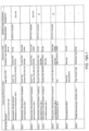
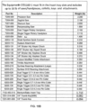
- Container ID 1605 indentifies and describes the specific type of container 90-4600 that was previously subjected to a sterilization validation process. When the sterilization process results are known to or are suspected to be affected by the type of container or the type of sterile barrier used for an equipment load, container ID may be associated with either content ID or VSPM data sets or both. If the type of container or sterile barrier used during a sterilization process is known to not affect sterilization results, container ID may not be associated with content ID or VSPM data sets.
- a container identified identifies a specific container serial number provided by an OEM or within the medical facility.
- the container ID can identify and translate to the container type, sterile barrier used, the electronic sensor module 200, 460, 560, 660, 760, 1000, 1050, 1080 type or sensor module configuration.
- Other data associated with content ID 1610 or VSPM 1150 data or both listed in figure 19 can be useful, but not necessary when using different embodiments of this invention.
- VSPM 1150 are transmitted from the docking station to the electronic sensor module and are stored in module memory 1022 ( FIG. 14 ). For example, if the container is being loaded and programmed with content ID 1610-1 and tray ID Stryker 7102- 450-010, only the VSPM 1150-S-l associated with content ID 1610-1 and associated sterilization process are transmitted from memory 1412 to memory 1022.
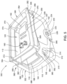
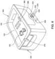
- Container assembly 1700 is employed when the efficiency of the sterilizing process is reduced or rendered ineffective as a result of the presence of a filter over the through openings in the container.
- a filter may have this affect on the sterilizing process is because owing to the composition of the filter and the composition of the sterilant, the presence of the filter inhibits the flow of sterilant through the filter.
- the presence of a filter may adversely also affect sterilization is because, the sterilant when exposed to the material forming the filter, undergoes a chemical reaction that reduces the efficacy of the sterilant.
- a filter container assembly 1700 typically does not include a filter.
- the vent is open and flow through the vent is unrestricted at least for the time period the container and the contents therein are undergoing a sterilization cycle.
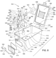
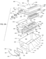
- Container cover 1710 and container vent assembly 1720 can be retrofitted to any the previously described containers 100, 402, 502 and 802 in order to provide the containers with a cover that automatically closes after the completion of a sterilization process cycle. While container vent assembly 1720 is shown mounted to cover 1710, container vent assembly 1720 alternatively can be mounted to any of the side panels of container 402. By relocation the container vent to a different panel it may allow steriliant to enter and exit more efficiently to affect sterilization of the contents of the container. Also, more than one container vent 1720 positioned on one or more panels may be used on a single container.
- Container vent assembly 1720 is mounted to top panel 1712. More specifically, container vent assembly 1720 is received by opening 1718.
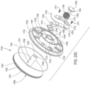
- Container vent assembly 1720 comprises a circular carriage 1722, cap 1760, circuit board 1770 and linear solenoid 1780.
- Carriage 1722 includes an outer ring 1728 connected to a central drum 1734 by cross members 1724. Outer ring 1728 is perpendicular to cross members 1724. A peripheral rim 1726 extends perpendicularly away from and surrounds ring 1728. A recess 1730 is defined between ring 1728 and cross members 1724.
- Carriage 1722 and container vent 1760 are formed from injection molded plastic.
- Carriage 1722 is mounted in opening 1718. Rim 1726 rests on top surface 1714 supporting carriage 1722. The outer surface of ring 1728 abuts the annular portion of panel 1712 defined by opening 1718. In one embodiment, carriage 1722 is press fit into opening 1718. In another embodiment, carriage 1722 is sealingly affixed to panel 1712 using an adhesive or sealed mechanical fasteners.
- Central drum 1734 is cylindrical in shape and has a base 1736.
- An outer wall 1738 and an inner hub 1740 extend perpendicularly away from base 1736.
- Base 1736, outer wall 1738 and inner hub 1740 define a groove 1742 therein.
- a central bore 1744 extends entirely through base 1736 and inner hub 1740.
- Another bore 1746 extends perpendicularly through inner hub 1740 approximately midway along the length of inner hub 1740. Bore 1746 extends between groove 1742 and bore 1744.
- Several mounting bosses 1748 are affixed to base 1736 adjacent wall 1738. Mounting bosses 1748 extend perpendicularly away from base 1736 into groove 1742. Mounting bosses 1748 are used to attach circuit board 1770 to carriage 1722.
- Cap 1760 includes a circular disc 1761 that is attached to a cylindrical shaft 1765.
- Disc 1761 has an outer annular side 1762.
- An annular groove 1763 is defined in side 1762. Groove 1763 is dimensioned to receive a circular elastomeric O-ring 1764.
- Cylindrical shaft 1765 extends perpendicularly away from the bottom side of disc 1761.
- Shaft 1765 has a central bore 1766 that extends partially into shaft 1765 parallel to the axis of shaft 1765.
- Shaft 1765 also has two bores 1767 and 1768 that extend partially into shaft 1765 perpendicular to the axis of shaft 1765. Bores 1767 and 1768 have a length that is approximately one half the diameter of shaft 1765. Bore 1767 is spaced from the bottom side of disc 1761 and bore 1768 is spaced from the terminal end of central bore 1766.
- a printed circuit board 1770 is affixed in groove 1742 by fasteners 1771.
- Groove 1742 is dimensioned to receive printed circuit board 1770.
- Fasteners 1771 extend through circuit board 1770 and are threaded into mounting bosses 1748.
- Several electrical components are mounted to circuit board 1770.
- a battery 1772, wireless transceiver 1773, solenoid housing 1774 and solenoid driver 1775 are mounted to circuit board 1770.
- Linear solenoid 1780 is mounted in and held by solenoid housing 1774.
- Battery 1772 is either a rechargeable or replaceable battery or supplies power to the components of circuit board 1770.
- Printed circuit board 1770 is in communication with one of electronic sensor modules 200, 460, 560, 660, 760 and 850.
- wireless transceiver 1773 receives wireless communications from one of the electronic sensor modules 200-850.
- an electrical cable 1779 is connected between circuit board 1770 and one of the electronic sensor modules 200-850.
- Solenoid driver 1775 is in communication with linear solenoid 1780 and causes linear solenoid 1780 to move an attached rod 1782.
- Rod 1782 is linearly movable between an extended position and a retracted position.
- a coil spring 1790 surrounds shaft 1765.
- a spring retainer 1792 is mounted over coil spring 1790 and includes a boss 1793 that extends into bore 1766.
- Spring retainer 1792 retains coil spring 1790 to shaft 1765.
- Spring retainer 1792 has an annular lip 1794 that extends over and abuts a distal end of spring 1790. The proximal end of spring 1790 abuts the terminal end of inner hub 1740.
- Spring retainer 1792 is either press fit into bore 1766 or is affixed in bore 1766 using an adhesive.
- Coil spring 1790 biases container vent 1760 to move towards carriage 1722. In an open position, as shown in FIG. 20B , a passage 1996 is formed between carriage 1722 and the bottom of disc 1761.
- Container vent 1760 is retained in the open position, by solenoid rod 1782 extending through inner hub bore 1746 and into container vent bore 1768. In this position, coil spring 1790 is compressed. Container vent 1760 is opened from a closed position in a two step process.
- a user uses an input device to trigger the retraction of solenoid rod 1782 out of bore 1767 by solenoid 1780.
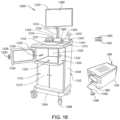
- the input device is the touch screen 1230 ( FIG. 15 ) of docking station 1200.
- the user manually grasps container vent 1760 and pulls upwardly on container vent 1760 moving container vent 1760 away from carriage 1722.
- Solenoid rod 1782 is outwardly biased by a spring (not shown) such that when container vent bore 1768 moves into axial alignment with inner hub bore 1746, rod 1782 automatically extends into container vent bore 1768 thereby holding container vent 1760 in the open position.
- lip cap assembly 1720 and container cover 1710 are part of the container assembly that undergoes a sterilization process cycle in a sterilization chamber.
- sensor module 200-850 After electronic sensor module 200-850 determines that the environment within container 402 during sterile processing were sufficient to meet or exceed a required set of environmental characteristics (VSPM 1150) to insure sterility of the surgical instruments being sterilized, sensor module 200-850 transmits an electrical signal via wireless transceiver 1773 or electrical cable 1779 to solenoid driver 1775 instructing solenoid driver 1772 to close container vent 1760.
- VSPM 1150 required set of environmental characteristics
- Solenoid driver 1775 causes solenoid 1780 to retract solenoid rod 1782.
- spring 1790 biases container vent 1760 to move into recess 1730 thereby closing passage 1796.
- the travel of container vent 1760 is limited by the abutment of the bottom of disc 1761 against cross members 1724.
- O-ring 1764 is compressed between the disc outer side 1762 and the inner surface of ring 1728 forming a seal.
- rod 1782 when container vent bore 1767 moves into axial alignment with inner hub bore 1746, rod 1782 automatically extends into container vent bore 1767 thereby holding container vent 1760 in the closed position.
- sensor module 200-850 transmits an electrical signal via wireless transceiver 1773 or electrical cable 1779 to solenoid driver 1775 instructing solenoid driver 1772 to cause solenoid 1780 to extend solenoid rod 1782.
- the distal end of rod 1782 In the extended position, the distal end of rod 1782 is received by and engaged with bore 1767, thereby locking container vent 1760 to carriage 1722.
- automatic closing container assembly 1700 and automatic closing lip cap assembly 1720 allows existing containers to be retrofitted with an automatic closing device that eliminates the need for filters or filter assemblies.
- passage 1796 is open, sterilant is able to readily enter and permeate container 402 without interference.
- passage 1796 is held open for an additional time period. This is to allow residual sterilant that may be in the container to evaporate and vent from the container.
- a benefit of allowing this venting of the sterilant is that, if the sterilant is potentially hazardous to tissue, the likelihood of residual sterilant contacting a patient or hospital personnel is substantially eliminated.
- the processor integral with the sensor module closes cap 1760 over passage 1796 when the sensor measurements indicate that the container environment has been at a select temperature or pressure for a select period of time. In other versions of the invention the processor closes the cap when the sensor measurements indicate that the container has been cycled through a set number of pressure set points.
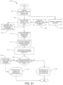
- Method 2100 illustrates an exemplary method by which the container assemblies 90, 300, 400, 500, 600, 700 800, 2900 and 4600 (90-4600) and electronic sensor modules 200, 460, 560, 660, 760, 850, 950, 1000, 1050, 1080 and 3500 (200-3500) presented within the preceding figures perform different aspects of the processes that enable one or more embodiments of the disclosure.
- Method 2100 is described specifically as being performed using container assembly 400 ( FIG. 7A ) and sensor module 1050 ( FIG. 12B ).
- method 2100 can be performed using any of container assemblies 90-800 and electronic sensor modules 200-3500.
- the description of the method is provided with general reference to the specific components illustrated within the preceding figures. In the discussion of FIG. 21 , reference will also be made to components from FIGS. 1-20 .
- Method 2100 begins at step 2102 where the equipment load of surgical instruments 180 is prepared for sterilization processing by an operator.
- Step 2102 includes the positioning of container 402 onto docking station 1200 or 1300 and if the container has a connector, connecting the corresponding connector 485, 1032 to the docking station. In an alternate embodiment, connecting the sensor module to the docking station can be made through a wireless communication system.
- handheld reader 1240 is used to scan the equipment load to be sterilized.
- equipment load or contents ID can be entered into the docking station or selected from a list or menu containing all equipment loads or content IDs that have associated VSPM data.
- Step 2102 further includes the placement of the equipment load into container 402 and enclosing the container with cover 450.
- the operator refers to the display screen 1260 shown by docking station 1200 or 1300 to view the correct equipment load items and instrument loading orientation. This display can help the operator in setting up the same equipment load and orientation that was used when validating and associated VSPM data to the equipment load.
- the sensors of electronic sensor module 460, 1050 are calibrated prior to use. Electronic sensor modules 460, 1050 are calibrated using docking station 1300.
- the surgical instruments 180 and/or tray 160 and/or container 402 are wrapped in a sterile barrier material prior to sterilization processing.
- sensor module memory 471, 1022 is programmed with validated sterilization process measurements (VSPM) data 1150 associated with the equipment load or content ID 1610.
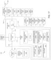
- Container programming software 1461 ( FIG. 17 ) acting on docking station processor 1410 ( FIG. 17 ) identifies the specific VSPM 1150 associated with the container equipment load, using the data obtained from step 2102, and transmits the VSPM 1150 via the connector 485 for storage on the sensor module memory 471, 1022.
- the transmitted VSPM 1150 are specific to the equipment load (content ID) to be sterilized.
- VSPM 1150 are transmitted via wireless means from the docking station to the container memory for storage.
- step 2108 confirms that the current VSPM data residing in sensor memory is proper for the container equipment load and transmitting of new VSPM 1150 from docking station to sensor memory is not performed.
- This alternate embodiment may be used for sensor modules that are repeatedly used for the same equipment load for example sensor module 760 that is mounted to a customized instrument rack 720 or dedicated container assembly.
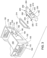
- sterilization verification software 1152 acting on processor 1020 turns on a yellow light emitting diode (LED) of LEDS 1030 (also shown as yellow LED 233 in FIG. 3 ) indicating to a user that the container assembly has not yet been processed through a sterilization process cycle.
- LED yellow light emitting diode
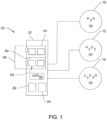
- the container 402 is placed into the sterilization chamber 52 ( FIG. 1 ) at step 2112.
- the container and its contents are subjected to a sterilization process, step 2114.
- the chamber is heated, pressurized and a sterilant, such as steam or hydrogen peroxide vapor is into the sterilization chamber.
- a sterilant such as steam or hydrogen peroxide vapor
- the sterilization process may include a cool down phase, drying phase or drawing a vacuum on the chamber to remove any residual condensed sterilant.
- the sterilization chamber is set to operate using a set of nominal chamber process parameters (CPP) 66 ( FIG. 1 ).
- CPP nominal chamber process parameters
- sterilization verification software 1152 acting on processor 1020 monitors and collects measurements from the respective electronic sensors with which it is in communication during the sterilization process cycle.
- the sensors measure the characteristics of the environment in the container.
- the software 1152 running on processor 1020 receives the signals representative of these environmental characteristics. These measures are stored as data 1156 in memory 1022.
- step 2116 compares the measurement data 1156 collected during the sterilization process, to the VSPM data 1150.
- sterilization verification software 1152 acting on processor 1020 determines if the measurements data 1156 during the performed sterilization process meets or exceeds the VSPM data 1150 values within the VSPM data set to insure sterilization of the container contents. For example, if VSPM 1150 has a minimum temperature and time value of 250 degrees Fahrenheit for 20 minutes, sterilization verification software 1152 compares these values to the recorded time and temperate measurement values in data 1156.
- step 2120 for containers that include closeable passages or vents.
- Step 2120 is the closing of the vent or passage. It should be understood that step 2120 is not executed immediately after the evaluation of step 2118 determines that the container environment met the requirements for a validated sterilization process. Instead, step 2120 is executed after the programmed time period, or detection of the set trigger event. This is ensure that between the completion of the actually sterilizing phases of the sterilization cycle and the closing of the vent there is sufficient time for the residual sterilant to vent from the container. For containers that do not contain closeable passages, step 2120 is of course, not executed. Method 2100 proceeds to step 2122.
- step 2122 processor 1020 indicates that the container contents were successfully sterilized by turning on a green LED such as LED 230 ( FIG. 3 ) or a green LED of LEDS 1030 ( FIG. 12B ) at step 2122.
- a green LED such as LED 230 ( FIG. 3 ) or a green LED of LEDS 1030 ( FIG. 12B ) at step 2122.
- step 2118 testing false is interpreted as indication that the contents of the container have not been sterilized to the desired levels.
- the processor proceeds to a step 2126.
- the processor 1020 presents an indication the contents of the container were not successfully sterilized by turning on or flashing a red LED such as LED 232 ( FIG. 3 ) or a red LED of LEDS 1030 ( FIG. 12B ). Not shown is the opening of the vent or port in versions of the invention with a cap that is selectively closed and open.
- step 2122 or step 2126 is the end of a single sterilization cycle.
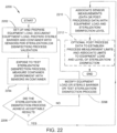
- Method 2200 begins at step 2202 where an equipment load of surgical instruments 180 is prepared for a Sterilization Validation by an operator.
- the surgical equipment load is selected and prepared to be validated for a selected sterilization modality.
- the surgical equipment load includes all items inside of the sterile barrier that are desired to be validated for sterilization.
- the equipment load may include surgical instruments 180 and an instrument tray or rack 160 when desired.
- Step 2202 may further include the placement of the surgical equipment load into container 402.
- all contents of the container that make up the equipment load are documented. Documentation can include a written bill of materials, an electronic bill of material, descriptions and part numbers of the contents, photographs taken of the contents or a combination of these types of documentation.
- Step 2202 also includes the placement of a biological challenge or inoculation of the equipment with biological challenge microorganisms in accordance with standard practices for sterilization assurance level validation or disinfection validation.
- One standard practice for inoculation of the equipment with microorganisms for steam sterilization can be found in ANSI/AAMI/ISO TIR17665-2 : 2009 , Sterilization of health care products-Moist heat-Part 2: Guidance on the application of ANSI/AAMI/ISO 17665-1 .
- Step 2202 includes completing the sterile barrier for the container which may be wrapping the container in a sterile barrier material, installing new filters, setting the container vents appropriately or other appropriate methods of completing the sterile barrier for the container, sterile barrier type and sterilization modality.
- For container assembly 400 installing new filters 440 and latching the lid assembly 450 to seal with container 402 completes the sterile barrier.
- data recording software 1155 stored on memory 471, 1022 is triggered to operate on processor 1020.
- Data recording software 1155 monitors and records evaluation process measurements, as measured by the sensor module, during a test sterilization process cycle for storage on the sensor module memory 471, 1022.
- the container 402 is placed into the sterilization chamber 52 ( FIG. 1 ) and the test sterilization process cycle within sterilization chamber 52 is started (step 2204).
- the sterilization chamber is typically set to operate using a set of nominal chamber test process parameters.
- a sterilant such as steam or hydrogen peroxide vapor is introduced into the sterilization chamber.
- the sterilization process cycle typically includes a cool down phase or an evacuation phase to remove any residual and/or condensed sterilant.
- data recording software 1155 acting on processor 1020 monitors and collects measurement data from the respective electronic sensors with which it is in communication during the test sterilization process.
- the sensors record the evaluation process measurements and conditions within the sterile barrier.
- the collected measurement data is stored in memory 1022 as data 1156.
- data recording software 1155 acting on processor 1020 collects water vapor data from water vapor sensor 1024, pressure data from pressure sensor 1026, temperature data from temperature sensor 1028 and hydrogen peroxide concentration data from hydrogen peroxide gas sensor 1052. In some embodiments, these data are simultaneously tracked and recorded as a function of time so as to capture the evaluation process measurements experienced inside of the sterile barrier on a time basis.
- container 402 is removed from the sterilization chamber 52 and the equipment load is evaluated for the level of sterilization achieved.
- an operator incubates and reads the biological challenge (or inoculated microorganisms) and determines if the survival rate of the microorganisms is below a pre-determined desired level.
- a 0% survival rate of the microorganisms indicate that the evaluation process measurements are adequate to insure destruction of all pathogens during sterilization processing.
- the operator can modify the equipment load, the nominal sterilization process parameters or the sterile barrier.
- the operator can modify one or more of these items, or any other controllable items that can affect the test sterilization process results.
- the modification of chamber (52) process parameters can include increasing one or more process parameters of the sterilization chamber 52.
- the temperatures level and the lethal portion of the test sterilization process time are increased in step 2208.
- step 2208 includes modifying the contents of container 402. For example, fewer surgical instruments 180 are placed inside the sterile barrier.
- Method 2200 then returns to step 2202 where the container 402 and equipment load is re-processed in sterilization chamber 52 repeating the steps until a desired level of sterilization is achieved at step 2206.
- the recorded sensor measurements are collected from sensor module memory 1022 and the measurements become validated sterilization process measurements (VSPM) associated to the equipment load.
- VSPM 1150 are based on the received evaluation measurement data 1156 that were functionally confirmed to act on the contaminants within the equipment load wherein the evaluation measurements become validated measurements.
- process measurement validation software 1466 acting on docking station processor 1410 reads the recorded evaluation measurement data 1156 from sensor module memory 1022 and stores the data on docking station memory 1412 at step 2210. Also in this embodiment at step 2210, an operator uses the evaluation measurement data 1156 recorded by the sensor module to determine and generate values for validated sterilization process measurements (VSPM) 1150. After the VSPM 1150 are determined, the operator inputs VSPM 1150 to docking station 1200, 1300 and directs VSPM 1150 to be stored to memory 1412.
- process measurement validation software 1466 acting on docking station processor 1410 automatically generates VSPM 1150 from evaluation measurement data 1156 and stores the data on docking station memory 1412 at step 2210.
- correlation of the equipment load to the VSPM completes process step 2210 for the desired level of sterilization.
- the operator establishes measurement limits for VSPM 1150.
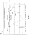
- Measurement limits could include upper and lower limit values for one or more sensor reading included in VSPM 1150 data set. Reading limits could include only an upper or only a lower limit. For example, in one embodiment, an operator can determine that a minimum or lower time limit experienced during the test sterilization processing is 20 minutes and a maximum or upper time limit is 40 minutes. In another embodiment, an operator can determine that a lower temperature limit experienced during the test sterilization process is 270° Fahrenheit.
- the operator sets the measurement limits for VSPM 1150 and directs the measurement limits to be stored to memory 1412.
- Optional step 2212 is completed when the measurement limits for VSPM 1150 are correlated to the equipment load for the desired sterilization level. Method 2200 then ends.
- step 2206 the definition of determining what constitutes whether or not a load of instruments was successfully sterilized in step 2206 is a function of the acceptable degree of sterilization for the instruments. Some instruments are considered adequately sterilized if they are only subjected to disinfection. Disinfection it is understood has a lower sterility assurance level than sterilization. Thus method 2200 as well as the sterilization process and equipment of this invention can be used to provide instruments that are sterile but not as sterile as typically required for instruments applied to tissue below the skin.
- the key difference in the environmental characteristics in the containers will be the rate at which these characteristics change.
- the concentration of the sterilant in the more porous container will rise at a faster rate than the concentration in the less porous container.
- the primary difference will be the time it takes for the concentration of sterilant adjacent the instruments forming the load to reach the desired, the validated levels. As long as the concentration of sterilant is at the validated concentration level for the validated time period, the instruments forming the load will reach the desired sterility level.
- This feature of the invention frees the hospital from having to sterilize a specific load of instrument by always placing those instruments in a specific container. If a container a designed for a set of instruments is not available for use, the instruments can be placed in an alternate container. It is only necessary that sensing unit integral with this container be able to (1) measure the characteristics internal to the container and (2) compare the measured environmental characteristics to the VSPM for the load. When these conditions are met, the alternative container can hold instruments during sterilization and its sensing unit will provide an indication regarding whether or not the instruments were successfully sterilized.
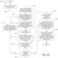
- FIG. 23 a flowchart of another method 2300 of determining, correlating and validating sterilization process measurements (VSPM) 1150 is shown.
- Method 2300 is discussed as being performed using container assembly 400 ( FIG. 7A ) and sensor module 1050 ( FIG. 12B ).
- any of the preceding container assemblies 90-800 and electronic sensor modules 200-1080 can be used to perform method 2300.
- the description of the method is provided with general reference to the specific components illustrated within the preceding figures. In the discussion of FIG. 23 , reference will also be made to components from FIGS. 1-20 .
- Method 2300 describes the steps for an operator to validate and equipment load through a Sterilization Assurance Level Validation.
- the surgical equipment load is selected and prepared to be validated for a selected sterilization modality for example steam, chemical or hydrogen peroxide.
- the surgical equipment load includes all items inside of the sterile barrier that is desired to be validated for sterilization.
- Step 2302 includes the positioning of container 402 onto docking station 1200 or 1300 and if the container has a connector, connecting the corresponding connector 485, 1032 to the docking station.
- all contents of the container that make up the equipment load are documented. Documentation can include a written bill of materials, an electronic bill of material, descriptions and part numbers of the contents, photographs taken of the contents or a combination of these types of documentation.
- handheld reader 1240 can be used to scan container 402, tray 160 and the surgical instruments 180 to aid in the documentation of the equipment load.
- a biological challenge device, biological indicator or a microorganism inoculation process is used to create a biological challenge for Sterilization Assurance Level Validation.
- These biological devices or processes include a known number of microorganisms that have a resistance to the mode of sterilization in use. These biological loads are used to determine if the proper sterilization level with a test sterilization process has been achieved for a given equipment load.
- the equipment load is placed into container 402 that contains electronic sensor module 460 and is enclosed with cover 450 assembly including appropriate sterile barrier filters 440.
- data recording software 1155 stored on memory 471, 1022 is triggered to operate on processor 1020.
- Process measurement validation software 1466 ( FIG. 17 ) acting on docking station processor 1410 ( FIG. 17 ) transmits instructions for data recording software 1155 to monitor and record process measurements during a test sterilization process cycle for storage on the sensor module memory 471, 1022.
- Data recording software 1155 acting on processor 1020 monitors and records the process measurements during the test sterilization process cycle.
- the sterile barrier appropriate for the type of container and sterilization process is completed prior to placing the container into the sterilizer chamber 52.
- the container 402 is placed into the sterilization chamber 52 ( FIG. 1 ) and the test sterilization process cycle within sterilization chamber 52 is started (step 2312).
- the sterilization chamber is heated, pressurized and a sterilant, such as steam or hydrogen peroxide vapor are introduced into the sterilization chamber.
- the sterilization process cycle typically includes a cool down phase and drawing a vacuum on the chamber to remove any residual and/or condensed sterilant.
- the sterilization chamber is set to operate using a nominal set of test process parameters.
- software 1155 monitors and collects time based data from the respective electronic sensors with which it is in communication during the sterilization process cycle.
- the sensors measure the environmental characteristics inside the sterile barrier.
- the collected measurements are stored as data 1156.
- data recording software 1155 acting on processor 1020 collects water vapor or humidity data from humidity sensor 1024, pressure data from pressure sensor 1026, temperature data from temperature sensor 1028 and hydrogen peroxide concentration data from hydrogen peroxide vapor sensor 1052. Measurement data can be stored into memory 1022 until transferred to docking station memory at step 2320.
- step 2314 the appropriate tests are executed to determine whether or not the instruments forming the load are sterile to the acceptable level.
- the means by which theses are performed are not part of the invention.
- step 2316 an operator determines the results of the test of step 2314 indicate whether or not the instruments forming the load were acceptably sterilized. If the evaluation of step 2316 tests false, the instruments are subjected to a subsequent test sterilization process, steps 2306-2312 are reelected. the subsequent sterilization process is, prior to the execution of this process, in a step 2318, modified so there is at least one difference between the just executed test sterilization process and the subsequent test sterilization process.
- This modification to the sterilization process can include increasing one or more process parameters of the sterilization chamber 52. In one embodiment, the temperature level or the process cycle time are increased in step 2318. In another embodiment, step 2318 includes modifying the contents of container 402. For example, fewer surgical instruments 180 are use for the equipment load or a different type of sterile barrier design can be used.
- Step 2314 is reexcuted to determine whether or not the results of the test indicate that the instruments forming the container load were successfully sterilized.
- step 2316 After a sterilization process, the results of the evaluation of step 2316 can test true.
- the operator designates the data 1156 recorded by the sensors to determine values as the validated sterilization process measurements (VSPM) 1150 for the load.
- the VSPM 1150 data are associated to the load in step 2302.
- the operator inputs VSPM 1150 and associated equipment load to docking station 1200, 1300 using keyboard 1426 or an electronic data transfer method and directs VSPM 1150 to be stored to memory 1412 in association with the equipment load.
- process measurement validation software 1466 acting on docking station processor 1410 automatically generates VSPM 1150 from real time measurement data and stores the data on docking station memory 1412 at step 2322.
- correlation of the equipment load to the VSPM completes process step 2322 for the desired level of sterilization.
- the operator establishes measurement limits for VSPM 1150.
- Measurement limits include upper and/or lower limit values for one or more process measurements to be included in VSPM 1150. For example, in one embodiment, an operator can determine that a minimum or lower temperature limit for the desired sterilization level is 270°F for the first 2 minutes and another minimum temperature limit 272 °F for the next 3 minutes. The determination of process limits is performed using data collected from one or more sterilization process validation cycles each with different sterilization processing measurements and conditions. After the process measurement limits are determined, the operator sets the process measurement limits for VSPM 1150 and correlates them to the equipment load using keyboard 1426 or electronic data transfer and directs the process measurement limits to be stored to memory 1412. Additionally, the correlation of VSPM data set to the equipment load is stored to memory 1412. Method 2300 then ends.
- XVIII Operational Method To Determine And Correlate Validated Sterilization Process Measurement Using Overkill Methods.
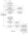
- FIG. 24 a flowchart of an additional method 2400 of determining and correlating validated sterilization process measurements (VSPM) 1150 is shown.
- Method 2400 is discussed as being performed using container assembly 400 ( FIG. 7A ) and sensor module 1050 ( FIG. 12B ).
- any of the preceding container assemblies 90-800 and electronic sensor modules 200-1080 can be used to perform method 2400.
- the description of the method is provided with general reference to the specific components illustrated within the preceding figures. In the discussion of FIG. 24 , reference will also be made to components from FIGS. 1-20 .
- Method 2400 starts at step 2402 where the equipment load of surgical instruments 180 is selected for sterilization.
- the equipment load is defined as all items inside of the sterile barrier which can include not only the surgical instruments 180 but also an instrument rack 160 when present. Instrument racks can aid in affecting sterilization by positioning instruments with difficult to reach locations in preferential orientations for the steriliant to penetrate and perform sterilization.
- a biological test device or biological challenge organisms are placed within the equipment load typically at a difficult to sterilize location (s). For example, if the equipment load has a instrument with a small diameter and a long closed end lumen, a biological challenge can be placed into the hardest to reach location at the closed end. The biological challenge is processed through the test sterilization process cycle along with the surgical instruments.
- the biological challenge carries a biological agent. During a successful sterilization process cycle, the biological agent is typically killed.
- the biological challenge includes a known number of microorganisms that have a know resistance to the mode of sterilization in use. For validation of a disinfection process, a minimum of 3 log reduction in the number of surviving microorganisms is required. For a biological challenge starting with 10A 6 organisms, a 3 log reduction would result in at least 10A 3 organisms killed. For validation of a sterilization process for an equipment load, a minimum of 6 log reduction in the number of surviving microorganisms is required.
- step 2405 an operator documents the type of biological challenge used and the location of the biological challenge within the equipment load.
- the operator may enter this information into the docking station using keyboard 1426 or electronic data transfer (i.e. importing scans or documents).
- step 2405 includes using a camera to take a picture of the biological challenge locations on the equipment load in container 402 and saving the image captured to docking station memory 1412.
- the equipment load is documented and then is placed into container 402 that contains electronic sensor module 460 and is enclosed with cover 450, completing the sterile barrier at step 2406.
- the operator inputs the type and quantity of surgical instruments, the type of tray and other items within the sterile barrier.
- Container 402 is placed on docking station 1200 or 1300 and connected to the docking station using connector 485.
- step 2407 the operator documents the equipment load of surgical instruments to be sterilized and the location of the sensors within container 402 with a photograph.
- the photograph can capture the equipment load, the orientation of the instruments and equipment within the load and the type and location of the sensors within the container.
- Step 2407 includes using a camera to take a picture of the contents and sensors within container 402 and saving the image captured to docking station memory 1412.
- data recording software 1155 stored on memory 471, 1022 is triggered to operate on processor 1020.
- Process measurement validation software 1466 ( FIG. 17 ) acting on docking station processor 1410 ( FIG. 17 ) transmits instructions for data recording software 1155 to monitor and record process measurements during a test sterilization process cycle for storage on the sensor module memory 471, 1022.
- Data recording software 1155 acting on processor 1020 monitors and records the process measurements during the test sterilization process cycle.
- the container 402 is placed into the sterilization chamber 52 by an operator ( FIG. 1 ) and the test sterilization process cycle within sterilization chamber 52 is started (step 2412).
- the test sterilization process cycle at step 2412 is performed using a one-half test sterilization process within the sterilization chamber 52.
- a one-half test sterilization process for a standard 4 minute autoclave steam cycle at 270°F would be a 2 minute autoclave steam cycle at 270°F.
- a one-half test sterilization cycle for Hydrogen Peroxide 4 pulse cycle would be a 2 pulse cycle.
- the sterilization chamber 52 is heated, pressurized and a sterilant, such as steam or hydrogen peroxide vapor is introduced into the sterilization chamber according to the half lethal chamber process parameter values.
- data recording software 1155 acting on processor 1020 monitors and collects time based data from the respective electronic sensors with which it is in communication during the sterilization process cycle.
- the sensors monitor the operating process measurements and conditions within the respective container they are mounted.
- the collected time based measurement data are stored in memory 1022 as data 1156.
- data recording software 1155 acting on processor 1020 collects humidity data from humidity sensor 1024, pressure data from pressure sensor 1026, temperature data from temperature sensor 1028 and hydrogen peroxide concentration data from hydrogen peroxide gas sensor 1052. These measurements are typically taken simultaneously as a function of time.
- step 2414 includes determining if a greater than a 6 log reduction in the number of surviving microorganisms has occurred .
- an operator determines if 100 percent or the desired quantity of the biological challenge microorganisms have been killed.
- the set of test chamber process parameters can be modified at step 2418 by an operator.
- the modification of test chamber process measurements can include increasing one or more process parameters of the sterilization chamber 52.
- the temperature level or the process cycle time are increased in step 2418.
- step 2418 includes modifying the contents of container 402. For example, fewer surgical instruments 180 are placed in tray 160 or a different type of sterile barrier material can be used.
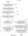
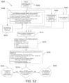
- FIG. 26 a flowchart of a method 2600 of loading surgical instruments into a container prior to sterilization processing is shown.
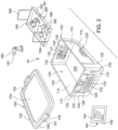
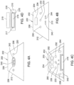
- Method 2600 is explained as being performed using container assembly 100 ( FIGS. 2-4C ) and docking station 1200 ( FIG. 15 ).
- method 2500 can be utilized with any of the described container assemblies with sensor modules or docking stations.
- the description of the method is provided with general reference to the specific components illustrated within the preceding figures. In the discussion of FIG. 26 , reference will also be made to components from FIGS. 2-4C , 15 and 17 .
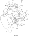
- the operator scans the bar code or RFID tag 135 on container 100 and the bar code or RFID tag 167 on tray 160 using handheld reader 1240.
- container loading software 1464 acting on processor 1410 searches container/tray configuration data 1465, selects a display screen 1260 from data 1465 corresponding to the respective scanned bar codes and RFID tags and causes the display screen 1260 to be shown on display 1230.
- the display screen 1260 illustrates the surgical instruments 180 to be loaded into tray 160 and the correct position and orientation of the surgical instruments 180 to be loaded.
- the operator scans a first surgical instrument bar code or RFID tag 181 at step 2608 using handheld reader 1240.
- container loading software 1464 acting on processor 1410 determines if the scanned surgical instrument 180 is a correct surgical instrument to be loaded into tray 160 using container/tray data 1465.
- container loading software 1464 acting on processor 1410 indicates that the wrong surgical instrument has been selected for loading by changing the video screen 1260 at step 2612.
- a red warning sign is flashed on display 1230 and an alarm sounded instructing the operator that they have selected an incorrect instrument.
- Method 2600 then returns to step 2608 where the next surgical instrument 180 to be loaded is scanned by the operator.
- the operator places the surgical instrument 180 into tray 160 with reference to the position and orientation information illustrated on display screen 1260 (step 2614).
- Display screen 1260 guides the operator during placement of surgical instruments into tray 160.
- the container loading software 1464 running on processor 1410 determines if the tray 160 is fully loaded with surgical instruments 180. If this evaluation tests negative, the operator in a reexcution of step 2608 scans the next instrument 180 to be loaded. When the evaluation determines the tray is full the processor 1410 at step 2618 causes a display screen 1260 to indicate all of the surgical instruments are loaded into tray 160 and that container 100 is ready for further processing .
- container loading software 1464 acting on processor 1410 transmits container/tray data 1465 to hospital computer system 1454 to update database 1456 with the current location and status of the loaded container, tray and surgical instruments.
- container/tray data 1465 updates database 1456 with the location of container 100, the specific surgical instruments 180 contained in tray 160 and that the container and contents are currently not sterile.
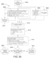
- FIG. 27 a flowchart of a method 2700 of calibrating sensors or verifying sensor accuracy and electronic sensor modules is shown.
- Calibration and sensor accuracy verification is used to check (verify) and/or adjust (calibration) the sensor response to a known set of simulated or generated environment conditions.
- Calibration and sensor accuracy verification methods are used to insure sensor measurements are accurate when used to generate VSPM data or verify VSPM data with sensor modules.
- Method 2700 is explained as being performed using container assembly 400 ( FIGS. 7A-7C ) , sensor module 1050 ( FIGS. 12B , 14 ) and docking station 1300 ( FIGS. 16 , 17 ).
- method 2700 can be utilized with any of the sensor modules described herein. The description of the method is provided with general reference to the specific components illustrated within the preceding figures.
- Method 2700 begins at step 2702 where an operator positions container assembly 400 to rest on docking station shelf 1342 or into calibration chamber 1320 and connects docking station cable 1340 to container connector 485. The operator also connects docking station connectors 1336 and 1338 together such that docking station 1300 is in communication with container assembly 400 for sensor calibration. More specifically, docking station controller 1402 is in communication with electronic sensor module controller 1120.
- sensor calibration software 1460 acting on processor 1410 causes a display screen 1260 to be shown on display 1230. If the sensor module has sensors that require calibration or require sensor performance verification, the display screen 1260 illustrates the container 402 and sensors to be calibrated and operator instructions to affect a proper calibration or sensor verification. If not already positioned, the operator places container assembly 400 into calibration chamber 1320 and closes door 1326.
- sensor calibration software 1460 acting on processor 1410 causes calibration chamber 1320 and electronic sensor module 1050 to execute a sensor calibration process or sensor verification cycle.
- Sensor calibration process at step 2708 may include turning on and operating steam generator 1430, hydrogen peroxide generator 1432, pressure pump 1434, vacuum pump 1436 and heater 1438.
- Steam generator 1430, hydrogen peroxide generator 1432, pressure pump 1434, vacuum pump 1436 and heater 1438 all operate according to a pre- defined set of calibration operating parameters generated by sensor calibration software 1460 acting on processor 1410 and transmitted via input/output interface circuit 1414.
- sensor calibration software 1460 acting on processor 1410 triggers sensor calibration software 1154 acting on processor 1020 to operate one or more generator systems to calibrate water vapor sensor 1024, pressure sensor 1026, temperature sensor 1028 and hydrogen peroxide sensor 1052.
- sensor calibration software 1460 acting on processor 1410 queries and receives feedback from calibration software 1154 acting on processor 1020 as to the success or failure of the calibration process on each sensor.
- Calibration software 1460 acting on processor 1410 determines if all of the sensors have been correctly calibrated or verified to the within specified accuracy.
- Calibration software 1460 acting on processor 1410 causes a display screen 1260 to be shown on docking station 1300 indicating the defective sensor (s).
- calibration software can instruct sensor module to provide a visual indication, for example using flashing LEDs, to the operator that a calibration failure occurred.
- Step 2712 In response to the sensors 1024-1052 being correctly calibrated and/or verified to the specified measurements, the sensors are indicated as being successfully calibrated at step 2712.
- Calibration software 1460 acting on processor 1410 causes a display screen 1260 to be shown on docking station 1300 indicating that all of the sensors 1024-1052 in container assembly 400 have been correctly calibrated or verified and are ready to be used in their appropriate sterilization process. Method 2700 then terminates.
- sensor calibration software 1460 is set to require the calibration of the sensors based on the number of times the sensors are used .
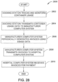
- FIG. 28 a flowchart of a method 2800 of monitoring container usage and billing on a fee per use basis is shown.
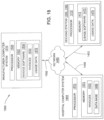
- Method 2800 is explained as being performed using docking station 1200 ( FIG. 18 ), manufacturer computer system 1510 ( FIG. 18 ) and hospital computer system 1454 ( FIG. 18 ).
- Method 2800 is used with any of the previously described containers 90-800.
- Method 2800 is described with reference to FIG. 18 and FIG. 28 .
- invoice software 1530 acting on manufacturer computer system processor 1520 periodically generates invoices 1532 based on usage data 1472.
- the invoices are stored to memory 1522.
- Invoice software 1530 operating on processor 1520 periodically transmits invoices 1532 to hospital computer system 1454 at step 2808.
- invoices 1532 are generated and transmitted on a weekly basis from manufacturer computer system 1510 to hospital computer system 1454.
- hospital computer system 1454 receives invoices 1532 and stores the invoices to memory 1572 for payment processing. Method 2800 then ends.
- Method 2800 is used in conjunction with a business model where docking station 1200, sensor modules or containers 90-800 are leased or rented to a medical facility or hospital.
- the medical facility or hospital pays for using the docking stations, sensor modules and containers on a fee per use basis as determined by usage software 1470 and invoice software 1530.
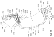
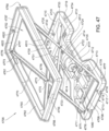
- distal end 3120 Two diametrically opposed portions of distal end 3120 are removed to define diametrically opposed arcuate shaped recesses 3132. The remaining portions of distal end 3120 form two diametrically opposed arcuate shaped shoulders 3134. The inner most edges of shoulders 3134 adjacent inner annular surface 3122 are beveled. Two threaded bores 3136 are defined in the base of each recess 3132. Bores 3136 extend perpendicularly from the base of each recess 3132 partially into sleeve 3118.
- Fingers 3138 and 3140 extend perpendicularly away from inner annular surface 3122 partially into thru bore 3125. Fingers 3138 and 3140 are diametrically opposed to each other on opposite sides of bore 3125 and are located toward the proximal end of bore 3125. Finger 3140 has a larger width than finger 3138.
- Annular groove 3142 is located in body rear surface 3108 spaced from and surrounding the opening of thru bore 3125. Groove 3142 is dimensioned to receive O-ring 3144 ( FIG. 32 ). The O-ring 3144 is seated in groove 3142. The O-ring 3144 forms a seal between receiver housing 3102 and plate 3350. In some versions of the invention an adhesive is used to hold O-ring 3144 in groove 3412.
- a rectangular shaped chamber 3146 is defined in triangular extension 3105 and has an opening towards front surface 3106. Chamber 3146 is dimensioned to receive a printed circuit board as will be described later.
- Terminal assembly 3150 is mounted in receiver housing 3102.
- Terminal assembly 3150 includes several elongated electrically conductive terminals 3152 that are electrically separated by an insulator 3154.
- Terminals 3152 are formed from a conductor material such as a copper alloy.
- Insulator 3154 is a material such as polyimide that is molded around terminals 3152 to form terminal assembly 3150.
- terminal assembly 3150 is placed in the same mold that is used to injection mold receiver housing 3102 from plastic. In another embodiment, terminal assembly 3150 is hermetically sealed to receiver housing 3102. After molding or sealing, terminal assembly 3150 is an integral part of receiver housing 3102. Terminal assembly 3150 defines an internal passage 3155 within sleeve 3118 through which terminals 3152 extend.
- terminal assembly 3150 is a flexible circuit that is inserted into internal passage 3155 within sleeve 3118. The flexible circuit is then held in place using a silicone adhesive or other appropriate curable adhesive or sealant.
- Terminals 3152 further have flush proximal contact ends 3156 that face towards bore 3125. Terminals 3152 also have distal contact ends 3158 that extend perpendicularly away from the sleeve outer surface 3124. Contact ends 3156 and 3158 are electrically connected to other electrical components as will be described later.
- another set of terminals 3160 may extend through passage 3155 and through another passage 3162 defined in extension 3105. Terminals 3160 have ends 3164 that terminates in chamber 3146 and ends 3166 that extends perpendicularly away from sleeve outer surface 3124 and are adjacent to contact ends 3158.
- an optional embodiment may contain an electronic sterile barrier monitoring system with Hall Effect printed circuit board 3170 which has an attached Hall Effect sensor 3172.
- Hall Effect printed circuit board 3170 is mounted in chamber 3146 and is electrically connected to terminal ends 3164 by suitable methods such as soldering or wire bonding.
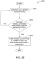
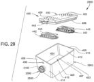
- Hall Effect sensor 3172 detects the presence or absence of magnet 448 ( FIG. 29 ).
- Hall Effect sensor 3172 detects the magnetic field generated by magnet 448 and transmits an electrical signal indicating a detected magnetic field.
- lid latch 496 is pivoted away from Hall Effect sensor 3172 causing sensor 3172 to detect the absence of a magnetic field and transmits an electrical signal indicating no magnetic field.
- Retainer ring 3200 is generally round in shape and has a proximal face 3202, a distal face 3204, an outer annular surface 3206 and an inner annular surface 3208. The outer peripheral edge of distal face 3204 is beveled. Threads 3210 are defined in inner annular surface 3208. Retainer ring threads 3210 mate with receiver housing threads 3129 in order to secure and seal sensor module receiver 3100 to container 2902. Threaded bores 3212 extend perpendicularly from distal face 3204 partially into retainer ring 3200.
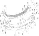
- Cover 3250 is generally round in shape with an extended section 3252.
- Cover 3250 has a distal face 3254, a proximal rim 3255, an outer annular surface 3256 and an inner step 3258.
- Inner step 3258 defines inner annular surface 3262.
- Inner annular surface 3262 terminates at proximal face 3254 and defines an opening 3263.
- a circular skirt 3260 extends in a proximal direction away from step 3258 and terminates at rim 3255. Skirt 3260 and annular surface 3262 defines thru bore 3264. The outer peripheral edge of distal face 3254 is beveled.
- Two diametrically opposed arcuate ribs 3270 extend perpendicularly from inner annular surface 3262 into bore 3264. The inner edges of ribs 3270 are beveled. The distal facing surface of ribs 3270 is flush with proximal face 3254.
- Two holes 3272 are defined in each rib 3270. Holes 3272 extend entirely through rib 3270. Ribs 3270 define two diametrically opposed arcuate gaps 3274 located between each of ribs 3270.
- Extended section 3252 is formed with a rectangular circuit board holder 3280.
- Holder 3280 includes a distal facing opening 3282 and a bottom wall 3284.
- Holder 3280 is open at distal face 3254.
- Apertures 3286 are defined in bottom wall 3284.
- a container printed circuit board (PCB) 3800 is mounted and retained in holder 3280. Opening 3282 is dimensioned to receive PCB 3800. Specifically, PCB 3800 is fastened to bottom wall 3284 by self tapping screws 3290 threaded into apertures 3286. Standoffs 3292 are positioned between bottom wall 3284 and PCB 3800 in order to space PCB 3800 from bottom wall 3284. Screws 3290 also extend through standoffs 3292. The components of container PCB 3800 will be described later.
- a transparent lens 3294 is mounted to distal face 3254 covering opening 3282. Lens 3294 allows a user to visually see light emitting diodes mounted to PCB 3800. Lens 3294 is attached to distal face 3254 using ultrasonic welding or is heat staked.
- PCB 3800 is electrically connected to terminal assembly 3150 ( FIG. 33 ). Specifically, PCB 3800 is connected to terminal ends 3158 and 3166 by suitable methods such as soldering or wire bonding. PCB 3800 is in communication with optional embodiment containing Hall Effect PCB 3170 via terminals 3160 ( FIG. 33 ).
- An annular groove 3532 is defined in outer annular surface 3508. Groove 3532 is dimensioned to receive a circular O-ring 3534. O-ring 3534 is seated in groove 3532. O-ring 3534 forms a seal with the inner annular surface 3122 ( FIG. 33 of sleeve 3118 ( FIG. 33 ).
- Channels 3540 and 3541 are defined in the case outer annular surface 3508. Channels 3540 and 3541 are diametrically opposed to each other on opposite portions of the circumference of case 3502.
- Channel 3540 has an entrance opening 3542 ( FIG. 31 ) that is adjacent proximal end 3504.
- Channel 3541 has an entrance opening 3543 (not shown) that is adjacent proximal end 3504.
- Channel 3541 and entrance opening 3542 are formed to have a larger or wider width than channel 3540 and entrance opening 3542.
- Channel 3540 angles from opening 3542 in a distal direction along the circumference of surface 3508 and terminates in an L- shaped trap 3544.
- Channel 3541 angles from opening 3543 in a distal direction along the circumference of surface 3508 and terminates in another L-shaped trap 3544.
- Case 3502 also includes a connector passage 3550 that is located between one of the traps 3544 and proximal end 3504.
- Connector passage 3550 extends perpendicularly through second skirt 3520 into cavity 3530.
- Connector passage 3550 is dimensioned to receive a connector 3750 that is attached to circuit board assembly.
- Threaded bores 3554 are defined in the proximal face of dividing wall 3510 located at the bottom of cavity 3530. Threaded bores 3554 extend perpendicularly into wall 3510 and are dimensioned to receive the external threaded distal end 3558 of PCB standoffs 3556. PCB standoffs 3556 also have an internal threaded proximal end or head 3560. PCB standoffs 3556 are screwed into bores 3554 forming a support for circuit board assembly 3700.
- Assembly 3700 has a printed circuit board (PCB) 3701 that is generally planar and doughnut shaped.
- PCB 3701 includes a proximal facing side 3702 and a distal facing side 3704 a circular opening 3706 is defined through the center of PCB 3701.
- PCB 3701 is mounted in case cavity 3530.
- PCB distal side 3702 rests on and is supported by standoffs 3556 with side 3702 abutting head 3560.
- Skirt 3520 surrounds the outer circumferential edge of PCB 3700. In this position, head 3523 ( FIG. 36 ) and drum 3522 ( FIG. 36 ) extend through central opening 3706.
- Screws 3710 extend through PCB holes 3712 and are received by internally threaded heads 3560 retaining PCB 3701 to case 3502.
- PCB 3701 is a multi-layer printed circuit board that includes numerous printed circuit lines 3716 for the interconnection of electrical components and sensors mounted on PCB 3701.
- a battery 3720, processor 1020, memory 1022, I/O interface 1124 and wireless transceiver 1138 are mounted to the distal facing side 3704 of PCB 3701.
- Battery 3720 supplies electrical power to the components of circuit board assembly 3700.
- Processor 1020, memory 1022, I/O interface 1124 and wireless transceiver 1138 are the same as previously described in FIGS. 12B and 13 .
- One or more sensors are mounted to the removable sensor module 3500 and connected to PCB 3701.
- sensors are mounted to proximal facing side 3702 of PCB 3701.
- Water vapor 1024, pressure sensor 1026 and temperature sensor 1028 are mounted to side 3702.
- Water vapor sensor 1024, pressure sensor 1026 and temperature sensor 1028 are the same as previously described in FIGS. 12B and 13 .
- also mounted to side 3702 is an optical sensor 1052 that senses the amount of infrared (IR) or ultraviolet (UV) light transmitted through an optical path length 3770 within container 2902.
- optical sensor 1052 detects and measures concentrations of hydrogen peroxide vapor (H 2 O 2 ) ⁇
- optical sensor 1052 detects water vapor or another gas or vapor where absorbance characteristics of the gas or vapor are known.
- Optical sensor 1052 includes an IR or UV source or emitter 1056, an optical reflector or mirror 3764 and an IR or UV receiver or detector 1058 mounted to side 3702.
- Light filters can be mounted around source 1056 or detector 1058 to remove any undesired light wavelengths.
- Mirror 3764 is positioned to reflect incident light energy towards detector 1058.
- Mirror 3764 is formed from a material that reflects emitter energy 1056 back to detector 1058 such as vacuum deposited aluminum on glass.
- FIG. 38 illustrates details of container printed circuit board (PCB) 3800.
- PCB 3800 is mounted in cover circuit board holder 3280 ( FIG. 34 ).
- PCB 3800 is generally planar and rectangular in shape.
- PCB 3800 includes a proximal facing side 3802 and a distal facing side 3804.
- PCB 3800 is a multi-layer printed circuit board that includes numerous printed circuit lines (not shown) for the interconnection of electrical components and in certain embodiments sensors mounted on PCB 3800.
- Holes 3810 are defined in PCB 3800. Screws 3290 ( FIG. 31 ) pass through holes 3810 in order to retain PCB 3800 to cover 3250 ( FIG. 31 ).
- a battery 3820, controller 3830, one or more LEDs 3842, 3844 3846 are all mounted to the distal facing side 3804.
- Battery 3820 supplies electrical power to the components of PCB 3800.
- Controller 3830 is a microcontroller that includes an internal memory that stores sets of instruction or software.
- PCB 3800 may also include memory that can store data such as measurement data from sterilization process, VSPM data, usage data or other workflow process data for example the operator who programmed the sensor module with VSPM data or operator who assembled the equipment load into container or the time and date of the sterilization process.
- the PCB 3800 combined with the removable sensor PCB 3700 functions like steam sensor modules 1000, hydrogen peroxide sensor module 1050, combined steam and hydrogen peroxide sensor module, or other sensor modules 200, 460, 560, 660, 760, 850 described herein.
- PCB 3800 will have some additional electronic components, some redundant with removable sensor module PCB 3700 so after removable sensor module 3500 is removed, PCB 3800 memory may contain information tied to the specific sterilization process, equipment load, operator information, programming information and other information required to track, record or monitor business processes, regulation processes or quality control processes for sterilization events.
- Controller 3830 is in communication with optional Hall Effect circuit board 3170 ( FIG. 31 ) via terminal 3162 ( FIG. 33 ). When removable sensor module 3500 is coupled to sensor module receiver 3100 ( FIG. 31 ), controller 3830 is in communication with processor 1020 via I/O interface 1024. Controller 3830 allows for data and instructions to be sent and received from processor 1020.
- Red LED 3842, yellow LED 3844 and green LED 3846 provide visual information to a user of container assembly 2900.
- LEDS 3842, 3844 and 3846 are viewed by a user through transparent lens 3294 ( FIG. 31 ).
- red LED 3842 indicates that container 2902 and its contents have been processed through a sterilization cycle that was unsuccessful in meeting a pre-determined set of minimum validated sterilization process measurements such as previously described VSPM 1150 ( FIG. 19 ). As such the contents of container 2902 are considered to be non-sterile.
- yellow LED 3842 indicates that container 2902 and its contents have not been processed through a sterilization cycle.
- green LED 3846 indicates that container 2902 and its contents have been processed through a sterilization cycle that was successful in meeting a pre-determined set of minimum validated sterilization process measurements such as previously described VSPM 1150 ( FIG. 19 ). As a result, the contents of container 2902 are considered to be sterile.
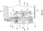
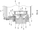
- FIGS. 39-43 illustrate a sequence of steps in the insertion and removal of removable sensor module 3500 into and from sensor receiver 3100.
- removable sensor module apparatus 3000 is shown in an initial or first position where sensor module 3500 is separated from receiver 3100.
- plate 3350 is compressed by springs 3382 against face seal O-ring 3144 forming a seal between distally directed annular face 3355 ( FIG. 35 ) and O-ring 3144.
- this seal and plate form part of a sterile barrier enclosure with container assembly 2900.
- lock mechanism 3400 is in a locked state.
- lock mechanism 3400 prevents plate 3350 from being opened or moved away from receiver housing 3102 maintaining a sealed position.
- lock mechanism 3400 In the locked position, lock mechanism 3400 is in an uppermost location where raised wall 3408 ( FIG. 35 ) abuts the upper side wall of step 3362 ( FIG. 35 ) and rods 3412 are positioned adjacent to and in abutting relationship to bracket arms 3306 preventing movement of plate 3350 in the proximal direction away from receiver housing 3102.
- sensor module 3500 is shown in a second position being loaded into receiver 3100.
- lid 450 has been removed from container 2902 and removable sensor module 3500 has been manually inserted into opening 3263 ( FIG. 34 ) and bore 3125 ( FIG. 34 ) of sleeve 3118 ( FIG. 34 ).
- O-ring 3534 forms a seal with the inner annular surface 3122 ( FIG. 33 ) of sleeve 3118 ( FIG. 33 ).
- head 3523 will eventually contact and abut the distal facing side of boss 3374 limiting movement in the proximal direction.
- fingers 3138 and 3140 are aligned with channel openings 3542 ( FIG. 31 ).
- Plate 3350 is still in a sealed and locked position.
- lock mechanism 3400 In the unlocked position, lock mechanism 3400 is in a lowermost location where raised wall 3408 ( FIG. 35 ) abuts the lower side wall of step 3362 ( FIG. 35 ) and lever end 3418 abuts the outer surface of plate 3350. This prevents further downward movement of lever 3414. Also, in the unlocked position, the two upper rods 3412 are positioned below the upper bracket arms 3306 and the two lower rods are in axial alignment with holes 3320 ( FIG. 35 ) allowing movement of plate 3350 in the proximal direction away from receiver housing 3102.
- Case 3502 is then rotated an additional 45°. As a result of this rotation, fingers 3138 and 3140 track along channels 3540. Thus results in case 3502 being drawn in the proximal direction towards bracket 3302. Because case 3502 is coupled to plate 3350, the rotation of case 3502 also causes a like movement of plate 3350 in a proximal direction away from receiver housing 3102 opening plate 3350. As plate 3350 moves in the proximal direction, springs 3382 are compressed and rods 3412 also move in a proximal direction past bracket arms 3306 and through holes 3320 ( FIG. 35 ). Plate 3350 moves away from O-ring 3144 creating a passage 4110 between plate 3350 and sensor circuit board assembly 3700. Passage 4110 allows sensors on circuit board assembly 3700 to be exposed to the operating environment and conditions within container 2902.
- case 3502 is now in a position where the distal end 3506 of case 3502 has moved slightly past distal face 3254 of cover 3250 and into bore 3264 ( FIG. 34 ).
- Surgical instruments 180 to be sterilized are manually loaded into container 2902 and cover 450 is placed over container 2902.
- Locking lid latch 496 is moved to a locked position retaining cover 450 to container 2902.
- pivoting of lid latch 496 causes magnet 448 to be positioned in proximity to Hall Effect sensor 3172 such that Hall Effect sensor 3172 senses the magnetic field generated by magnet 448.
- Container assembly 2900 is now ready to be processed through a sterilization process cycle within sterilization chamber 52 ( FIG. 1 ).
- removable sensor module 3500 monitors and collects data in regards to the operating environment, conditions and process measurements within container 2902.
- lock mechanism 3400 is biased by coil spring 3426 ( FIG. 35 ) to move into the locked state.
- Coil spring 3426 causes lock mechanism 3400 to move to an uppermost location where raised wall 3408 ( FIG. 35 ) abuts the upper side wall of step 3362 ( FIG. 35 ) limiting upward movement of lock mechanism 3400 and rods 3412 are positioned adjacent to bracket arms 3306 preventing movement of plate 3350 in the proximal direction away from receiver housing 3102.
- plate 3350 is pulled outwardly. This results in the plate 3350 being pressed against O-ring 3144. This adds to the force springs 3382 apply to the plate so as to hold the plate in sealed and locked position.
- Sensor module 3000 is constructed so that a sterile seal is maintained between container 2902 and receiver 3100 regardless of the position of removable sensor module 3500.
- annular face 3355 ( FIG. 35 ) of plate 3350 and face seal O-ring 3144 form a sterile seal preventing contaminants from moving thru receiver 3100 and into container 2902.
- O-ring 3534 and inner annular surface 3122 ( FIG. 33 ) maintain another sterile seal whenever plate 3350 is in a open position forming another sterile barrier.
- some of the components that form part of the sensing assembly are mounted to the container.
- these components are mounted to the receiver.
- Components that may be so affixed to the receiver include the processor, the memory, the indicator lights or the battery. Also, owing some sensors may be permanently mounted to the container.
- FIG. 44 another embodiment of a docking station 1300 is shown.
- Docking station 4400 is used in conjunction with removable sensor apparatus 3000. Docking station 4400 is used during the loading of surgical instruments into containers 2902, to calibrate the sensors of removable sensor module 3500 and to recharge batteries.
- Docking station 4400 has many features in common with docking station 1300 previously described with reference to FIG. 16 .
- Docking station 4400 differs from docking station 1300 in that calibration chamber 1320 has been modified to eliminate door 1326 ( FIG. 16 ) and to add a fixed front panel 4410.
- Several sensor receivers 3100 are mounted to front panel 4410. While six sensor receivers 3100 are shown mounted to calibration chamber 1320, more or fewer sensor receivers 3100 can be used.
- Removable sensor modules 3500 are attachable and detachable with each of the sensor receivers 3100.
- the sensor receivers 3100 of docking station 4400 are connected to and in communication with docking station controller 1402 ( FIG. 17 ).
- sensor processor 1020 FIG. 37A
- docking station controller 1402 When sensor modules 3500 are inserted into receivers 3100, sensor processor 1020 ( FIG. 37A ) is in communication with docking station controller 1402 and docking station processor 1410 ( FIG. 17 ).
- Docking station 4400 contains steam generator 1430, hydrogen peroxide generator 1432, pressure pump 1434, vacuum pump 1436 and heater 1438 ( FIG. 17 ) all of which can be used as needed to provide known concentrations and values within calibration chamber 1320 during a calibration procedure.
- Docking station 4400 is used in conjunction with removable sensor apparatus 3000 in the same manner that docking station 1300 is used with container 402. Docking station 4400 is used to program removable sensor module 3500 with validated sterilization process measurements (VSPM) 1150 prior to sterilization processing as previously described in step 2108 of FIG. 21 . Docking station 4400 is used to recharge battery 3720 ( FIG. 37A ) in removable sensor module 3500. Docking station 4400 is used to calibrate the sensors in removable sensor module 3500 in the same manner as previously described in steps 2704-2714 of FIG. 27 .
- Sensor calibration software 1460 ( FIG. 17 ) is used by docking station 4400 during the calibration of the sensors associated with a respective removable sensor module 3500. Sensor calibration software 1460 at least partially controls the operation of steam generator 1430, hydrogen peroxide generator 1432, pressure pump 1434, vacuum pump 1436 and heater 1438 during a calibration procedure.
- docking station 4400 can be used to program and calibrate a large number of removable sensor modules 3500 at the same time.
- FIG. 45 a flowchart of a method 4500 of determining if validated sterilization process measurements within a container have been achieved during a sterilization process using removable sensor modules 3500 is shown.
- Method 4500 illustrates an exemplary method by which container assemblies 3000 and removable sensor module 3500 presented within the preceding figures perform different aspects of the processes that enable one or more embodiments of the disclosure.
- FIG. 45 reference will also be made to components from FIGS. 29-44 .
- the equipment load of surgical instruments 180 ( FIG. 2 ) is prepared for sterilization processing by an operator.
- the surgical instruments are placed into tray 160 ( FIG. 2 ) and tray 160 is placed into container 2902.
- Cover 450 ( FIG. 40 ) is attached and closed to container 2902.
- the surgical instruments 180 and/or tray 160 and/or container 2902 are wrapped in a sterile barrier material prior to sterilization processing.
- sterilization verification software 1152 ( FIG. 14 ) executing on processor 1020 turns on container yellow LED 3844 ( FIG. 38 ) indicating to a user that the container assembly has not yet been processed through a sterilization process cycle.
- the container 402 is placed into the sterilization chamber 52 ( FIG. 1 ) at step 4512 and the sterilization process cycle within sterilization chamber 52 is started (block 4514).
- the sterilization chamber is heated, pressurized and a sterilant, such as steam or hydrogen peroxide gas are pumped into the sterilization chamber.
- the sterilization process cycle also includes a cool down phase and drawing a vacuum on the chamber. These sub-steps remove residual condensed sterilant from the container.
- the sterilization chamber is set to operate using a set of chamber process parameters (CPP) 66 ( FIG. 1 ).
- CPP 66 are the set of nominal process parameter settings within the sterilization chamber.
- the sterilization chamber is set to operate using CPP 66.
- sterilization verification software 1152 executing on processor 1020 monitors and collects real time data from the respective electronic sensors in sensor module 3500 during the sterilization process.
- the sensors monitor the environmental characteristics within their respective containers.
- the collected real time operating data is stored in memory 1022 as data 1156 ( FIG. 14 ).
- sterilization verification software 1152 executing on processor 1020 collects water vapor data from water vapor sensor 1024, pressure data from pressure sensor 1026, temperature data from temperature sensor 1028 and hydrogen peroxide concentration data from hydrogen peroxide gas sensor 1052. All of the data recorded during the sterilization process is stored as data 1156 in memory 1022.
- Method 4500 proceeds to step 4526 where sterilization verification software 1152 executing on processor 1020 indicates that the container contents have been successfully sterilized by turning on green container LED 3846. ( FIG. 38 ).
- additional data related to the sterilization process may be transferred to container memory of PCB 3800 for storage, workflow process or quality control practices.
- measurement data, VSPM programmed data set, sterilization verification results, sterilization date and VSPM programming operator can be stored on container memory on PCB 3800.
- the container assembly is removed from the sterilization chamber and the removable sensor module 3500 is detached from container 2902 at step 4528.
- the contents of container 2902 remain in a sealed sterile state during and after sensor module 3500 has been disconnected from container 2902. Method 4500 then ends.
- Step 4524 is identical to previously described step 2126.
- Method 4500 then terminates .
- Container assembly 4600 uses a scissors mechanism 4700 to close a moveable frame 4750. The frame is closed after the sterilization process is executed and residual sterilant withdrawn from the container.
- Container assembly 4600 comprises a container 4602.
- Container 4602 of FIG. 46 is the same the previously described container 402 of FIG. 7A except that opening 414 and lid latches 496 have been omitted from container 402.
- container 4602 will be referred to using common reference numbers from FIG. 7A .
- Container assembly 4600 further includes a rack or tray 4620.
- Tray 4620 can be formed from suitable materials such as stainless steel or aluminum.
- Tray 4620 comprises a generally planar rectangular shaped base 4622 that is perforated with an array of holes 4626. Holes 4626 allow sterilant to circulate below base 4622.
- Base 4622 has an upper surface 4623 and a bottom surface 4624.
- Four support feet 4628 are mounted to base 4622 and extend perpendicularly downward from the bottom surface 4624. Feet 4628 rest on the upper surface of support skeleton 4710 when tray 4620 is placed into container 4602.
- Tray 4620 is used to hold medical/surgical instruments 180 within container 4602 during sterile processing.
- Tray 4620 includes a pair of spaced apart handles 4632 that are mounted to opposite ends of base 4622. Handles 4632 allow a user to grasp and lift tray 4620.
- Tray 4620 is formed with several support members 4638 that extend upwardly from base 4622. Medical/surgical instruments 180 rest on and are supported by support members 4638. Support members 4638 are dimensioned and shaped so that medical/surgical instruments 180 are held and retained in a preferred orientation for sterile processing. It is important for some medical/surgical instruments 180 to be oriented in certain geometric orientations during sterile processing such that sterilant can readily enter and exit from the surgical instruments.
- Cover 4650 is used to cover and enclose container 4602.
- Cover 4650 includes a generally rectangular shaped panel 4652 that is surrounded by a raised peripheral flange 4654.
- Cover 4650 is formed from materials such as stamped aluminum or other suitable materials.
- Two latches 4658 are mounted to opposite sides of cover 4650. Each latch 4658 is diametrically opposed to the other and is attached to flange 4654.
- Latch 4658 mates with a clip 4758 that extends outwardly from two ends of moveable frame 4750. When cover 4650 is moved downwardly into contact with moveable frame 4750, latch 4658 slightly pivots and engages clip 4758 resulting in the retention of cover 4650 to frame 4750.
- Cover 4650 has an elastomeric gasket 456 (see FIG.
- Container assembly 4600 further includes a scissor mechanism 4700.
- Scissor mechanism 4700 is received by interior cavity 420 of container 4602 and rests on bottom panel 407.
- Scissor mechanism 4700 is used to raise and lower frame 4750 during sterilization processing of container assembly 4600.
- Scissor mechanism 4700 comprises a dog bone shaped skeleton 4710 that is linked by a pair of central cross-members 4712. Skelton 4710 has opposed ends 4738 and 4739. Skeleton 4710 and cross members 4712 define three cavities 4713, 4714 and 4715 within skeleton 4710.
- Four openings 4716 are defined in opposite ends of skeleton 4710. Openings 4716 receive locking fingers 4717 that have an attached slotted head 4718 that faces upwardly from the top surface of skeleton 4710.
- skeleton 4710 resting on container bottom panel 407, slotted heads 4718 are rotated using a tool such as a screwdriver forcing locking fingers 4717 into engagement with a retention feature (not shown) on the inside surface of sides walls 405 and 406.
- the engagement of locking fingers 4717 with the retention features fixes skeleton 4710 to container 4602 and retains scissor mechanism 4700 to container 4602.
- skeleton is realesably secured to the bottom of container.
- skeleton is fastened to bottom of container.
- skeleton is coupled to container in a manner that allows the skeleton and actuator system to create enough sealing force between the moveable frame and container to prevent ingress of microorganisms.
- Sensor module 1050 is mounted in cavity 4713 and retained to skeleton 4710 by retention means 4711. Sensor module 1050 is the same as previously described in FIG. 12B except that an actuator driver circuit 4708 is incorporated into module 1050.
- Rotary actuator 4720 is mounted in cavity 4714.
- Rotary actuator 4720 is attached to side sections 4721 of skeleton 4710 by a C-shaped clamp 4722.
- a threaded shaft 4723 extends perpendicularly away from one end of rotary actuator 4720.
- Rotary actuator 4720 can be rotated in either a clockwise or counterclockwise rotation causing a like a clockwise or counterclockwise rotation of threaded shaft 4723.
- Threaded shaft 4723 has a proximal end 4724 closest to actuator 4720, a center section 4725 and a distal end 4726.
- a moveable carriage 4730 is mounted in cavity 4715.
- Moveable carriage 4730 includes a rectangular shaped block 4731 that is positioned in cavity 4715.
- Block 4731 has a threaded center bore 4731 that extends entirely through block 4731 and is perpendicular to shaft 4723.
- Threaded shaft 4723 is screwed into threaded bore 4731 and extends out the distal side of block 4731.
- the distal end 4726 of shaft 4723 is received in a bearing 4732 that is mounted in end 4739 of skeleton 4710.
- Two diametrically opposed rods 4734 are fixed to and extend away from two ends of block 4731 in a perpendicular manner. Rods 4734 are received by diametrically opposed slots 4719 that are defined in sides of skeleton 4710 toward end 4739. The travel of moveable carriage 4730 in either direction is limited by the abutment of rods 4734 against the ends of slots 4731.
- Scissor mechanism 4700 further includes four elongated arms 4770.
- Each arm 4770 has a proximal end 4771, a center section 4772 and a distal end 4773.
- Apertures 4775 are defined through each respective proximal end 4771, center section 4772 and distal end 4773.
- Each aperture 4775 receives a retaining member 4776.
- the lower arms proximal end 4771 retaining member 4776 has a pin 4777 that extends into a hole 4778 in skeleton 4710. Pin 4777 allows the lower arm proximal ends 4771 to rotate with respect to skeleton 4710.
- the upper arm distal ends 4773 retaining members 4776 have pins 4777 that are received by slots 4761 that extend into frame 4750.
- Pins 477 extend perpendicularly away from distal arm ends 4773.
- Slots 4761 are dimensioned to be slightly larger than pins 4777 to allow pins 4777 to slide in slots 4761.
- apertures 4775 are dimensioned to be slightly larger than pins 4777 to allow the upper arm distal ends 4773 to rotate with respect to skeleton frame 4750.
- sensor module 1050 is programmed with validated sterilization process measurements (VSPM) 1150.
- Memory 1022 ( FIG. 14 ) is programmed with specific validated sterilization process measurements (VSPM) 1150.
- Container programming software 1461 FIG. 17 ) executing on docking station processor 1410 ( FIG. 17 ) identifies the specific VSPM 1150 associated with the container equipment load, optionally using the data obtained from handheld reader 1240 ( FIG. 44 ), and transmits the VSPM 1150 for storage on container memory 1022.
- the transmitted VSPM 1150 are specific to the equipment load to be sterilized.
- the connector 1338 and cable 1340 are then disconnected from connector 1032.
- Sterilization verification software 1152 executing on processor 1020 at step 4914 compares the observed real time data 1156, collected during the sterilization process cycle, to VSPM 1150.
- sterilization verification software 1152 operating on processor 1020 determines if the measured data 1156 during the performed sterilization process meets or exceeds the minimum or threshold VSPM 1150 values for each operating parameter to insure sterilization of the container contents. For example, if VSPM 1150 has a minimum temperature and time value of 250 degrees Fahrenheit for 20 minutes, sterilization verification software 1152 compares these values to the recorded time and temperature values in data 1156.
- processor 1020 executes a set of instructions such as sterile monitor software 1158 ( FIG. 14 ) that causes processor 1020 to monitor the electrical signal received from Hall Effect sensor 4820 ( FIG. 47 ) during storage. If cover 4650 is opened, the electrical signal from Hall Effect sensor 4820 changes, triggering processor 1020 to move the moveable frame 4750 to the open position.
- sterile monitor software flashes an LED instead of opening the moveable frame. The moveable frame 4750, in the open position, indicates to a technician that the contents of the container 2602 are no longer considered to be sterile.
- method 5000 can be performed using any of container assemblies 90-800 and electronic sensor modules 200-1080.
- the description of the method is provided with general reference to the specific components illustrated within the preceding figures. In the discussion of FIG. 50 , reference will also be made to components from FIGS. 7A , 12B and 15 .
- Generally method 5000 is described as being implemented via container processor 1020 and particularly the execution of code provided by software/firmware modules acting within processor 1020. It is however appreciated that certain aspects of the described methods may be implemented via other processing devices and/or execution of other code.
- the sensors of electronic sensor module 1050 are calibrated prior to use.
- Electronic sensor modules 1050 is calibrated using docking station 1300.
- the memory 1022 within container 402 is programmed with specific verified steam sterilization process parameters (VSPP) 1150.
- Container programming software 1461 FIG. 17
- docking station processor 1410 FIG. 17
- the transmitted VSPP 1150 are specific to the equipment load within the container to be sterilized.
- the VSPM 1150 include:
- LED yellow light emitting diode
- step 5102 the container 402 is placed into the sterilization chamber 52.
- Step 5014 is the starting of the sterilization process.
- the sterilization chamber is heated, pressurized and a steam sterilant is introduced into the sterilization chamber.
- the sterilization process cycle also includes a cool down phase and drawing a vacuum on the chamber to remove any residual condensed sterilant.
- the sterilization chamber is set to operate using a set of chamber process parameters (CPP) 66 ( FIG. 1 ).
- CPP 66 are the set of process parameter settings within the sterilization chamber.
- the sterilization chamber is set to operate using the CPP 66.
- the temperature of the load is referred to as a surrogate temperature because it can be difficult to provide sensors that monitor the temperature of the load. Instead, the sensors monitor the void near the load.
- the surrogate temperature should thus be considered substantially equal to if not identical to the actual temperature of the load.
- the temperature of this void is considered a surrogate for the temperature of the load. All of the data recorded during the sterilization process is stored as data 1156 in memory 1022.
- FIG. 51 illustrates an example graph 5100 of process parameter measurements taken by sensor module 1050 inside container 402 of instruments that were processed using a steam sterilization process. Only the exposure phase measurements are shown in the graph.
- FIG. 51 shows a graph 5100 of temperature and pressure versus time. The measurements include Tsteam (Tmeasured) or Tload 5102, Tair detector 5106 and pressure 5108. The graph also includes a superimposed graph of the calculated temperature for saturated steam (Tsat 5104) based upon the pressure measurement within the container.
- the VSPM 1150 include:
Landscapes
- Health & Medical Sciences (AREA)
- Epidemiology (AREA)
- Life Sciences & Earth Sciences (AREA)
- Animal Behavior & Ethology (AREA)
- General Health & Medical Sciences (AREA)
- Public Health (AREA)
- Veterinary Medicine (AREA)
- Chemical & Material Sciences (AREA)
- Chemical Kinetics & Catalysis (AREA)
- General Chemical & Material Sciences (AREA)
- Apparatus For Disinfection Or Sterilisation (AREA)
Applications Claiming Priority (4)
| Application Number | Priority Date | Filing Date | Title |
|---|---|---|---|
| US201361779956P | 2013-03-13 | 2013-03-13 | |
| EP20210450.1A EP3808384B1 (de) | 2013-03-13 | 2014-03-12 | Verfahren zur gewinnung von validierten sterilisationsverfahrensmessungen |
| EP14717010.4A EP2968633B1 (de) | 2013-03-13 | 2014-03-12 | Sterilisationsbehälter zur anzeige des sterilisierungsstatus von in dem behälter zu sterilisierenden chirurgischen instrumenten |
| PCT/US2014/024799 WO2014159696A1 (en) | 2013-03-13 | 2014-03-12 | Sterilization container capable of providing an indication regarding whether or not surgical instruments sterilized in the container were properly sterilized |
Related Parent Applications (2)
| Application Number | Title | Priority Date | Filing Date |
|---|---|---|---|
| EP14717010.4A Division EP2968633B1 (de) | 2013-03-13 | 2014-03-12 | Sterilisationsbehälter zur anzeige des sterilisierungsstatus von in dem behälter zu sterilisierenden chirurgischen instrumenten |
| EP20210450.1A Division EP3808384B1 (de) | 2013-03-13 | 2014-03-12 | Verfahren zur gewinnung von validierten sterilisationsverfahrensmessungen |
Publications (2)
| Publication Number | Publication Date |
|---|---|
| EP4578467A2 true EP4578467A2 (de) | 2025-07-02 |
| EP4578467A3 EP4578467A3 (de) | 2025-12-31 |
Family
ID=50478942
Family Applications (3)
| Application Number | Title | Priority Date | Filing Date |
|---|---|---|---|
| EP25177275.2A Pending EP4578467A3 (de) | 2013-03-13 | 2014-03-12 | Verfahren zur durchführung validierter sterilisationsverfahrensmessungen |
| EP20210450.1A Active EP3808384B1 (de) | 2013-03-13 | 2014-03-12 | Verfahren zur gewinnung von validierten sterilisationsverfahrensmessungen |
| EP14717010.4A Active EP2968633B1 (de) | 2013-03-13 | 2014-03-12 | Sterilisationsbehälter zur anzeige des sterilisierungsstatus von in dem behälter zu sterilisierenden chirurgischen instrumenten |
Family Applications After (2)
| Application Number | Title | Priority Date | Filing Date |
|---|---|---|---|
| EP20210450.1A Active EP3808384B1 (de) | 2013-03-13 | 2014-03-12 | Verfahren zur gewinnung von validierten sterilisationsverfahrensmessungen |
| EP14717010.4A Active EP2968633B1 (de) | 2013-03-13 | 2014-03-12 | Sterilisationsbehälter zur anzeige des sterilisierungsstatus von in dem behälter zu sterilisierenden chirurgischen instrumenten |
Country Status (8)
| Country | Link |
|---|---|
| US (4) | US10010636B2 (de) |
| EP (3) | EP4578467A3 (de) |
| JP (4) | JP6491186B2 (de) |
| CN (4) | CN113230425B (de) |
| AU (4) | AU2014244561B2 (de) |
| CA (2) | CA3122224C (de) |
| ES (1) | ES2857675T3 (de) |
| WO (1) | WO2014159696A1 (de) |
Families Citing this family (118)
| Publication number | Priority date | Publication date | Assignee | Title |
|---|---|---|---|---|
| CN109091686A (zh) * | 2012-08-01 | 2018-12-28 | 美国政府(由退伍军人事务部所代表) | 组织一个或多个受生物战剂污染的物品的消毒的方法 |
| CN113230425B (zh) | 2013-03-13 | 2023-07-14 | 史赛克公司 | 能够提供容器中的被灭菌手术器械是否被正确灭菌的提示的灭菌容器 |
| US10022464B2 (en) | 2013-08-02 | 2018-07-17 | Zuno Medical Inc. | Sterilization tray |
| US9616368B2 (en) | 2014-01-29 | 2017-04-11 | Turbett Surgical LLC | Sterilizing method and apparatus |
| US10391435B2 (en) | 2014-01-29 | 2019-08-27 | Turbett Surgical LLC | Sterilizing method and apparatus |
| US9724438B2 (en) | 2014-01-29 | 2017-08-08 | Turbett Surgical LLC | Sterilizing method and apparatus |
| US10881997B2 (en) | 2014-01-29 | 2021-01-05 | Turbett Surgical, Inc. | Method of sterilization verification |
| EP3110460B1 (de) * | 2014-01-30 | 2018-12-26 | Steelco S.p.A. | Vorrichtung für behandlung und transport medizinischer instrumenten in einer geschützten weise |
| CH709334B1 (fr) * | 2014-03-04 | 2018-08-15 | Dassym Sa C/O Lnnoparc | Procédé pour détecter une stérilisation d'une pièce pour un dispositif médical. |
| AU2015229592B2 (en) | 2014-03-11 | 2019-03-14 | Stryker Corporation | Sterilization container with battery powered sensor module for monitoring the environment in the container |
| US20150305404A1 (en) * | 2014-04-24 | 2015-10-29 | Adam Albert Rosales | Electronic Cigarette Cleaning and Charging Station |
| DE102014213942B4 (de) * | 2014-07-17 | 2016-01-28 | Christof-Herbert Diener | Vakuumanlage, insbesondere Plasmaanlage, mit einem rundum geschlossenen Kammerstrangpressprofil |
| DK3174489T3 (da) | 2014-07-31 | 2020-11-16 | Turbett Surgical Inc | Metode og anordning til at læsse |
| US10753050B2 (en) | 2014-09-23 | 2020-08-25 | Quality Mat Company | Industrial mats having cost effective core structures |
| FR3028408A1 (fr) * | 2014-11-13 | 2016-05-20 | Analytic- Tracabilite Hospitaliere | Tracabilite et suivi d'une boite de sterilisation et de son contenu |
| WO2016081319A1 (en) | 2014-11-21 | 2016-05-26 | Allosource | Enclosure for laser cutting of human tissue |
| US9507981B2 (en) * | 2014-12-09 | 2016-11-29 | Haldor Advanced Technologies Ltd | Association of processed items with process logs |
| WO2016138482A1 (en) | 2015-02-26 | 2016-09-01 | K&K Lukas LLC | Dry heat sanitizer and method of use |
| DE102015109415A1 (de) * | 2015-06-12 | 2016-12-15 | CertoClav Sterilizer GmbH | Autoklav mit portabler Steuer- und Bedieneinheit |
| WO2017024260A1 (en) | 2015-08-06 | 2017-02-09 | Zuno Medical, Inc. | Sterilization tray |
| CA2998327A1 (en) | 2015-09-11 | 2017-03-16 | Stryker Corporation | Sterilization enclosure for surgical instruments |
| WO2017062466A2 (en) | 2015-10-05 | 2017-04-13 | Stryker Corporation | Sterilizable enclosure for securing a portable electronic device |
| JP6796131B2 (ja) * | 2015-10-30 | 2020-12-02 | オーアンドエム ハリヤード インターナショナル アンリミテッド カンパニー | 滅菌パッケージングシステム |
| US10996112B2 (en) * | 2015-12-01 | 2021-05-04 | Maxim Integrated Products, Inc. | Systems and methods for correcting lag between sensor temperature and ambient gas temperature |
| US11648326B2 (en) | 2016-02-04 | 2023-05-16 | Xenex Disinfection Services Inc. | Cabinets for disinfecting objects |
| US11690927B2 (en) | 2016-02-04 | 2023-07-04 | Xenex Disinfection Services Inc. | Systems, cabinets and methods for disinfecting objects |
| US10561753B2 (en) | 2016-03-02 | 2020-02-18 | Asp Global Manufacturing Gmbh | Method of sterilizing medical devices, analyzing biological indicators, and linking medical device sterilization equipment |
| US10596287B2 (en) * | 2016-03-02 | 2020-03-24 | Asp Global Manufacturing Gmbh | Apparatus and method to link medical device sterilization equipment |
| US10668180B2 (en) | 2016-03-02 | 2020-06-02 | Asp Global Manufacturing Gmbh | Apparatus and method for sterilizing medical devices |
| US10443083B2 (en) | 2016-03-02 | 2019-10-15 | Asp Global Manufacturing Gmbh | Apparatus and method for analyzing biological indicators |
| CA3021503A1 (en) * | 2016-04-22 | 2017-10-26 | 3M Innovative Properties Company | Readers for process monitoring systems and methods of use |
| US10117959B2 (en) * | 2016-06-07 | 2018-11-06 | General Electric Company | Smart sterilization tracker tag |
| DE102016118083A1 (de) | 2016-09-26 | 2018-03-29 | Aesculap Ag | Medizinischer Sterilbehälter |
| FR3058733A1 (fr) * | 2016-11-15 | 2018-05-18 | Jean Francois Biron | Methode de validation d'un procede de sterilisation comportant deux contaminations successives |
| US10500297B2 (en) | 2016-11-21 | 2019-12-10 | Asp Global Manufacturing Gmbh | Apparatus and method for detecting improper positioning of removable component of sterilizing system |
| CN119896762A (zh) * | 2016-12-08 | 2025-04-29 | 舒万诺知识产权公司 | 过程监测装置 |
| EP3336781A1 (de) * | 2016-12-13 | 2018-06-20 | Sigma-Aldrich International GmbH | Elektronikbaugruppe zur drahtlosen übertragung von mindestens einer statusinformation |
| US10668177B1 (en) | 2016-12-13 | 2020-06-02 | Maxim Integrated Products, Inc. | Systems and methods for autoclave operating evaluation and verification |
| WO2018156928A1 (en) * | 2017-02-27 | 2018-08-30 | Applied Logic, Inc. | System and method for managing the use of surgical instruments |
| EP3383151B1 (de) * | 2017-03-28 | 2021-06-09 | FRIWO Gerätebau GmbH | Schutzgehäuse für ein elektronisches modul und montageverfahren |
| US11273230B1 (en) * | 2017-04-10 | 2022-03-15 | Ricciardi Carl L | Multi-function product disinfection cabinet |
| US10647461B2 (en) | 2017-05-23 | 2020-05-12 | Biosense Webster (Israel) Ltd. | Methods and apparatus for cleansing and packaging medical instruments or the like |
| CN107358030A (zh) * | 2017-06-16 | 2017-11-17 | 深圳市前海安测信息技术有限公司 | 医院消毒包灭菌信息管理系统及方法 |
| US10544608B2 (en) * | 2017-06-30 | 2020-01-28 | Tesla, Inc. | Glovebox controller systems and methods |
| US20190046024A1 (en) * | 2017-08-10 | 2019-02-14 | Ethicon, Inc. | Volume expanders for endoscopes |
| US9970813B1 (en) | 2017-09-14 | 2018-05-15 | Biosense Webster (Israel) Ltd. | UV detection of sterilant concentration and dissipation in a volume of a chamber |
| DE102017127723A1 (de) * | 2017-11-23 | 2019-05-23 | Schott Ag | Autoklavierbares medizinisches Gerät sowie Betätigungseinrichtung für ein autoklavierbares medizinisches Gerät |
| US10814027B2 (en) * | 2017-12-07 | 2020-10-27 | Asp Global Manufacturing Gmbh | Sterilization-assistance device |
| US10967084B2 (en) | 2017-12-15 | 2021-04-06 | Asp Global Manufacturing Gmbh | Flow restrictor |
| USD907233S1 (en) * | 2018-02-08 | 2021-01-05 | Guangdong Gt Ultrasonic Co., Ltd. | Ultrasonic cleaner |
| CA2998927A1 (en) * | 2018-03-22 | 2019-09-22 | Alpha Micro Tech Inc. | Data logger for dental autoclave |
| EP4389059B1 (de) * | 2018-03-23 | 2025-10-29 | Log10 B.V. | System zur wiederverarbeitung wiederverwendbarer medizinischer instrumente |
| US11786620B2 (en) | 2018-04-30 | 2023-10-17 | CathBuddy, Inc. | Handheld cleaner-disinfector for medical devices |
| US10639389B2 (en) | 2018-04-30 | 2020-05-05 | CathBuddy, Inc | Methods and devices for portable sterilization and containment of medical devices |
| KR102654724B1 (ko) | 2018-05-11 | 2024-04-03 | 에코랍 유에스에이 인코퍼레이티드 | 휴대용 포장 식품 용기를 위한 위생 시스템 |
| EP3790818A1 (de) | 2018-05-11 | 2021-03-17 | Ecolab USA, Inc. | Hygienesystem für einen tragbaren verpackten lebensmittelbehälter |
| WO2019220262A1 (en) * | 2018-05-17 | 2019-11-21 | Tuttnauer Ltd. | Sterilization monitor |
| MX2021002778A (es) * | 2018-09-28 | 2021-05-12 | O & M Halyard Inc | Sistema de deteccion de vulneraciones de esterilidad y sistema controlador para un recipiente de esterilizacion. |
| US10987185B2 (en) | 2018-09-28 | 2021-04-27 | O&M Halyard, Inc. | Sterility breach detection system and controller system for a sterilization container |
| DE102018125180A1 (de) * | 2018-10-11 | 2020-04-16 | Aesculap Ag | Sterilisationsverpackung für Sterilgut mit Sensorvorrichtung und Sterilisationsverfahren mit aktiver Sterilisationsprozessanpassung |
| WO2020128959A1 (en) * | 2018-12-21 | 2020-06-25 | 3M Innovative Properties Company | Activator system for biological indicator |
| US11141498B2 (en) * | 2019-01-25 | 2021-10-12 | Apple Inc. | Photo-oxidation removal of organic contamination for environmental sensor integration |
| WO2020167847A1 (en) | 2019-02-11 | 2020-08-20 | Hai Solutions, Inc. | Instrument sterilization device |
| US20220125964A1 (en) * | 2019-02-11 | 2022-04-28 | Hai Solutions, Inc. | Fiber optic sterilization device |
| EP4712306A3 (de) * | 2019-03-27 | 2026-04-15 | Stryker Corporation | Autoklavierbarer behälter zur sterilisation einer drahtlos aufladbaren batterie |
| EP3714762B1 (de) * | 2019-03-29 | 2023-08-23 | Picosun Oy | Verfahren und vorrichtung zum reinigen von medizinischen instrumenten und zum erkennen von rückständen darauf |
| JP7015586B2 (ja) * | 2019-05-06 | 2022-02-15 | 浙江大学 | 吸光断熱一体化光熱蒸発材料及びその調製方法と応用 |
| WO2020264367A1 (en) * | 2019-06-28 | 2020-12-30 | 3Derm Systems, Inc. | Monitoring surface cleaning of medical surfaces using video streaming |
| WO2021030377A1 (en) * | 2019-08-12 | 2021-02-18 | David George Barlow | Monitor and indicator system |
| US12292402B2 (en) | 2019-08-12 | 2025-05-06 | David George Barlow | Monitor and indicator system |
| CN110327479A (zh) * | 2019-08-14 | 2019-10-15 | 蚌埠学院 | 一种环氧乙烷灭菌监测方法及装置 |
| US12043424B2 (en) | 2019-09-09 | 2024-07-23 | Pavestone, LLC | Vented packaging arrangement and method |
| US11537973B2 (en) * | 2019-09-30 | 2022-12-27 | Ford Global Technologies, Llc | Food locker sanitation system for autonomous vehicles |
| US10874756B1 (en) * | 2019-10-08 | 2020-12-29 | Envirody Inc. | Sanitizing cabinet assembly and method of operation |
| US11786621B2 (en) * | 2019-10-10 | 2023-10-17 | Carefusion 2200, Inc. | Reusable tortuous path filters for sterilization containers |
| CN111348332B (zh) * | 2020-03-04 | 2022-03-04 | 江苏云与雾物联科技有限公司 | 一种多功能智能便携装置及多功能智能控制方法 |
| KR102631765B1 (ko) | 2020-03-06 | 2024-01-30 | 유브이 파트너즈 아이엔씨 | 소독 및 인간 기계 인터페이스 집적 회로 |
| US11820565B2 (en) | 2020-03-11 | 2023-11-21 | Sonoco Development, Inc. | Sterile barrier packaging system |
| CN115666437B (zh) * | 2020-04-03 | 2026-04-14 | 舒万诺知识产权公司 | 从灭菌包外部确定灭菌程序的有效性 |
| DE102020111712A1 (de) * | 2020-04-29 | 2021-11-04 | Aesculap Ag | Haltevorrichtung für Sterilgut, Sterilgut sowie Verfahren zur Sterilgutkreislauf-Überwachung |
| US11007292B1 (en) | 2020-05-01 | 2021-05-18 | Uv Innovators, Llc | Automatic power compensation in ultraviolet (UV) light emission device, and related methods of use, particularly suited for decontamination |
| US11185602B1 (en) | 2020-05-29 | 2021-11-30 | Edbertho Leal-Quiroz | Decontamination of body surfaces and articles with harmless radiation and related methods |
| US12203841B1 (en) * | 2020-06-18 | 2025-01-21 | The United States Of America As Represented By The Secretary Of The Army | Portable test system for uniform chemical concentration testing of personal protection products and method of use |
| DE102020117500A1 (de) | 2020-07-02 | 2022-01-05 | Aesculap Ag | Kommunikations- und Energieübertragungsmodul, Sterilbehälter, Sterilbehälter-Management-System und Lagervorrichtung |
| CN111803665A (zh) * | 2020-07-22 | 2020-10-23 | 广州狸园科技有限公司 | 一种多功能医用防护铅衣的烘干、灭菌装置 |
| US20220054666A1 (en) * | 2020-08-24 | 2022-02-24 | Covidien Lp | Ventilator filter sterilization systems and methods |
| DE102020124319A1 (de) | 2020-09-17 | 2022-03-17 | Aesculap Ag | Verwendung einer mobilen Energieumwandlungsanlage zum Betreiben einer medizinischen Vorrichtung und eines Sterilgutkreislauf-Überwachungssystems |
| CN112245610B (zh) * | 2020-10-16 | 2021-12-10 | 华浅近 | 一种骨科手术用螺钉消毒方法 |
| US11986566B2 (en) | 2020-11-02 | 2024-05-21 | Raytheon Company | System and method for decontamination of materials |
| DE102020129082A1 (de) | 2020-11-04 | 2022-05-05 | Aesculap Ag | Sterilcontainer mit Sendermodul und Sterilcontainer-Überwachungssystem |
| US11603551B2 (en) | 2020-12-02 | 2023-03-14 | Steritec Products Mfg. Co., Inc. | Biological indicators, and systems and methods for determining efficacy of sterilization |
| IT202100007223A1 (it) * | 2021-03-25 | 2022-09-25 | Cisa Production S R L | Impianto e procedimento per la sterilizzazione di strumenti chirurgici. |
| US20220313255A1 (en) * | 2021-03-30 | 2022-10-06 | Cilag Gmbh International | Smart packaging for tissue adjuncts |
| EP4066863A1 (de) * | 2021-03-30 | 2022-10-05 | Sartorius Biohit Liquid Handling Oy | Verpackung, verfahren und verwendung |
| US11935347B1 (en) * | 2021-03-31 | 2024-03-19 | United Services Automobile Association (Usaa) | Security and safety configurations for drone delivery |
| US12487439B2 (en) * | 2021-04-30 | 2025-12-02 | Technoculture Research Private Limited | Lens less imaging microscopy system |
| US20230024180A1 (en) * | 2021-05-14 | 2023-01-26 | Scican Ltd. | Systems and methods for tracking medical instruments cleaning and sterilization |
| US20230055383A1 (en) * | 2021-08-23 | 2023-02-23 | Summate Technologies, Inc. | Integrated Data Capture of Sterile and Non-Sterile Surgical Supplies and Implantables |
| US20230074512A1 (en) * | 2021-09-09 | 2023-03-09 | Vascular SafeGuard LLC | System for improving central line hygiene |
| IT202100026444A1 (it) * | 2021-10-15 | 2023-04-15 | Ecofiltri Srl | Sistema e metodo per testare dispositivi di sensoristica |
| CN118159306A (zh) * | 2021-11-11 | 2024-06-07 | 舒万诺知识产权公司 | 消毒指示传感器 |
| JP7448920B2 (ja) * | 2021-12-15 | 2024-03-13 | コニカミノルタ株式会社 | オゾン滅菌装置 |
| DE102022106282A1 (de) | 2022-03-17 | 2023-09-21 | Aesculap Ag | Sterilisierbehälter, Steuerungsvorrichtung und entsprechendes System |
| WO2023176216A1 (ja) * | 2022-03-17 | 2023-09-21 | Phcホールディングス株式会社 | 培養装置及び培養システム |
| EP4511070A4 (de) * | 2022-04-21 | 2026-04-08 | Plasma Bionics LLC | Sterilisationsvorrichtung |
| WO2024006479A1 (en) * | 2022-06-29 | 2024-01-04 | Twenty Twenty Therapeutics Llc | System, method, and apparatus for massaging the eyelid |
| CA3259923A1 (en) * | 2022-07-08 | 2024-01-11 | Medivators Inc. | GUIDED CONNECTION FOR ENDOSCOPE REMOVAL |
| DE102022131781A1 (de) * | 2022-11-29 | 2024-05-29 | Olympus Winter & Ibe Gmbh | Verfahren und System zum Selbstprüfen einer Endoskop-Wiederaufbereitungseinrichtung |
| CN116173278A (zh) * | 2023-02-28 | 2023-05-30 | 常州工学院 | 一种具有定位与环境识别功能的低温等离子体发射装置 |
| CN116440310B (zh) * | 2023-05-06 | 2025-07-11 | 珠海格力电器股份有限公司 | 消毒机控制方法、装置、消毒机及存储介质 |
| CN116560287B (zh) * | 2023-06-15 | 2023-11-14 | 珠海西格医疗设备有限公司 | 一种基于物联网的蒸汽灭菌器控制系统及方法 |
| US12164985B1 (en) | 2023-07-07 | 2024-12-10 | Cilag Gmbh International | System and method for selectively adjustable data exchange between a smart package and a requesting system |
| EP4566069A1 (de) * | 2023-07-07 | 2025-06-11 | Cilag GmbH International | Situationsadaptive markierung für intelligente verpackungssysteme |
| WO2025024190A2 (en) * | 2023-07-21 | 2025-01-30 | Steris Corporation | Sterilization packaging |
| WO2025193838A1 (en) * | 2024-03-12 | 2025-09-18 | Surgitray, Llc | Sterilization containers |
| FR3163576A1 (fr) * | 2024-06-21 | 2025-12-26 | Logiqal | Système de détection et de mesure de la concentration d’au moins un agent de stérilisation à l’état gazeux pour un stérilisateur basse température |
| US12298236B1 (en) | 2024-11-14 | 2025-05-13 | Kymanox Corporation | Systems and methods for monitoring a gas sterilization environment |
| US12496369B1 (en) | 2025-02-04 | 2025-12-16 | Sterilmetric Innovations, Llc | Systems and methods for monitoring a gas sterilization environment |
Family Cites Families (65)
| Publication number | Priority date | Publication date | Assignee | Title |
|---|---|---|---|---|
| DE3632675A1 (de) * | 1986-09-26 | 1988-04-07 | Aesculap Ag | Sterilisiervorrichtung fuer sterilisierbehaelter |
| DE3632674A1 (de) * | 1986-09-26 | 1988-04-07 | Aesculap Werke Ag | Sterilisierbehaelter fuer medizinische zwecke |
| EP0522083A4 (en) * | 1990-03-30 | 1993-05-19 | Iit Research Institute | Method and apparatus for rendering medical materials safe |
| US5364590A (en) * | 1993-05-07 | 1994-11-15 | American Sterlizer Company | Method for sterilization of objects |
| CN1198678A (zh) | 1995-10-06 | 1998-11-11 | 美国3M公司 | 消毒器测试系统 |
| GB9523717D0 (en) * | 1995-11-20 | 1996-01-24 | Mdh Ltd | Method and apparatus for hydrogen peroxide vapour sterilization |
| EP0776669A1 (de) | 1995-11-27 | 1997-06-04 | Minnesota Mining And Manufacturing Company | Testpackung für Sterilisatoren |
| US5788925A (en) * | 1996-02-16 | 1998-08-04 | Steris Corporation | Method for real time monitoring and control of load sterilization and parametric release |
| JPH10201830A (ja) * | 1997-01-24 | 1998-08-04 | Terumo Corp | 滅菌装置の表示装置 |
| US6428746B1 (en) * | 1997-09-18 | 2002-08-06 | Custom Ultrasonics Inc. | Method for determining the efficacy of a decontamination procedure |
| AU753047B2 (en) | 1997-11-14 | 2002-10-03 | Ethicon Inc. | Method for measuring the concentration of hydrogen peroxide vapor |
| NZ509852A (en) * | 1998-08-10 | 2002-11-26 | Univ Manitoba | Artificial test soil containing an endotoxin |
| JP3414291B2 (ja) * | 1998-12-14 | 2003-06-09 | 三浦工業株式会社 | 滅菌管理装置 |
| DE19913417C1 (de) | 1999-03-25 | 2000-09-14 | Wagner Hans | Sterilisierbehälter |
| CA2268042A1 (en) * | 1999-04-06 | 2000-10-06 | Scican, A Division Of Lux & Zwingenberger Ltd. | Apparatus and method for steam sterilization of medical and dental instruments |
| AUPQ036599A0 (en) | 1999-05-14 | 1999-06-10 | Fairmont Medical Products Pty Ltd | Sterilisation method and container therefor |
| US6318151B1 (en) | 1999-07-26 | 2001-11-20 | Abbott Laboratories | Self-contained sterilant monitoring assembly and method of using same |
| US6537491B1 (en) | 1999-07-26 | 2003-03-25 | Abbott Laboratories | Apparatus having sterilant monitoring system |
| US6517775B1 (en) | 1999-07-26 | 2003-02-11 | Abbott Laboratories | Sterilant monitoring assembly and apparatus and method using same |
| US6485979B1 (en) * | 1999-08-05 | 2002-11-26 | 3M Innovative Properties Company | Electronic system for tracking and monitoring articles to be sterilized and associated method |
| JP3066514U (ja) | 1999-08-10 | 2000-02-25 | 大東金網株式会社 | 医療用容器 |
| US6234310B1 (en) | 1999-09-03 | 2001-05-22 | Minntech Corp | Sterile packaging system |
| JP3674906B2 (ja) * | 2000-03-10 | 2005-07-27 | テクノエクセル株式会社 | 寿命表示器付き浄水器 |
| US6773678B2 (en) * | 2000-03-20 | 2004-08-10 | Endress + Hauser Conducta Gesellschaft Fur Mess Und Regeltechnik Mbh + Co. | Mounting system and retractable sensor holder for analytical sensors |
| FR2808003B1 (fr) * | 2000-04-25 | 2002-08-30 | Metrolog Services Metrologique | Conteneur de sterilisation a fermeture controlee par un appareil electronique |
| US6528016B1 (en) | 2000-06-27 | 2003-03-04 | Ethicon, Inc. | Method for rapidly determining the acceptability of loads to be sterilized |
| NL1017308C2 (nl) | 2001-02-07 | 2002-08-08 | Ask B V I O | Werkwijze en inrichting voor het bepalen van de procescondities bij sterilisatie. |
| US6612149B2 (en) * | 2001-02-15 | 2003-09-02 | Abbott Laboratories | Method and apparatus for calibration of instruments that monitor the concentration of a sterilant in a system |
| US6875399B2 (en) | 2001-05-11 | 2005-04-05 | Steris Inc. | Non-dispersive mid-infrared sensor for vaporized hydrogen peroxide |
| US7090808B2 (en) | 2001-07-09 | 2006-08-15 | Pharmaceutical Systems, Inc. | Apparatus for testing sterilization methods and materials |
| WO2003006963A1 (en) | 2001-07-10 | 2003-01-23 | Steris Inc. | Monitor and control using mid-infrared spectroscopy for vapor hydrogen peroxide processing technics |
| WO2003043666A1 (en) | 2001-11-16 | 2003-05-30 | Case Medical Inc | Rigid reusable sterilization container with thermostatic valve |
| US7122150B2 (en) * | 2002-01-11 | 2006-10-17 | 3M Innovative Properties Company | Electronic reader for sterilization monitors |
| JP4257065B2 (ja) * | 2002-02-28 | 2009-04-22 | オリンパス株式会社 | 滅菌装置 |
| US6884392B2 (en) * | 2002-11-12 | 2005-04-26 | Minntech Corporation | Apparatus and method for steam reprocessing flexible endoscopes |
| US6930493B2 (en) | 2003-03-14 | 2005-08-16 | Steris Inc. | Method and apparatus for monitoring detergent concentration in a decontamination process |
| ATE297227T1 (de) * | 2003-03-28 | 2005-06-15 | Ulrich Dr Kaiser | Prüfkörper, insbesondere zur überprüfung der penetrationseigenschaften eines sterilisiermittels in sterilisationsprozessen |
| US20050009191A1 (en) * | 2003-07-08 | 2005-01-13 | Swenson Kirk D. | Point of care information management system |
| US7169369B2 (en) * | 2003-08-01 | 2007-01-30 | Steris Inc. | Method and device for deactivating items and for maintaining such items in a deactivated state |
| AU2004290339A1 (en) * | 2003-11-05 | 2005-05-26 | Scican, A Division Of Lux And Zwingenberger Ltd. | System for management of processed instruments |
| US7452504B2 (en) | 2004-05-28 | 2008-11-18 | Ethicon, Inc. | Sterilization/disinfection cycle control |
| US7467890B2 (en) * | 2005-11-04 | 2008-12-23 | Custom Ultrasonics, Inc. | Portable chemical transfer/neutralizing containment system |
| AU2007224159B2 (en) * | 2006-03-06 | 2010-08-26 | American Sterilizer Company | Apparatus for deactivating instruments and devices |
| FR2899480B1 (fr) | 2006-04-10 | 2008-10-03 | Gred Sa | Systeme de desinfection d'instruments medicaux |
| DE602007010983D1 (de) | 2006-05-01 | 2011-01-13 | American Sterilizer Co | Wasserstoffperoxid-Zerstäuber |
| CN200953081Y (zh) * | 2006-06-21 | 2007-09-26 | 中国人民解放军第三军医大学第一附属医院 | 用于预真空压力蒸汽灭菌器的检测装置 |
| WO2008061313A1 (en) * | 2006-11-24 | 2008-05-29 | Mems-Id Pty Ltd | Tagging methods and apparatus |
| DE102007056261A1 (de) * | 2007-05-23 | 2008-11-27 | Helvoet Pharma Belgium N.V. | Vielzahl von in einem Transportbehältnis zusammengefassten Sterilisationsobjekten, Transportbehältnis, sowie Verfahren zur Sterilisierung von derartigen Objekten |
| US7827845B2 (en) | 2007-06-18 | 2010-11-09 | Codman & Shurtleff, Inc. | Method and kit for maintaining a sterile environment during calibration of a medical device |
| EP2185060B1 (de) | 2007-08-29 | 2012-04-18 | Ethicon, Inc | Automatisierter wiederaufbereiter für endoskop |
| US9757489B2 (en) | 2008-03-04 | 2017-09-12 | Symmetry Medical Manufacturing, Inc. | System and method for modular component sterilization case |
| DE102008030268B3 (de) * | 2008-06-19 | 2010-02-04 | Arzneimittel Gmbh Apotheker Vetter & Co. Ravensburg | Verfahren zum Befüllen von Doppelkammersystemen in vorsterilisierbaren Trägersystemen und vorsterilisierbares Trägersystem |
| US7880887B2 (en) | 2008-08-29 | 2011-02-01 | Phygen, Inc. | Apparatus and method for measuring the concentration of gases in a sterilization chamber |
| JP5160350B2 (ja) * | 2008-09-04 | 2013-03-13 | 富士フイルム株式会社 | 内視鏡洗浄消毒装置 |
| US20110011886A1 (en) * | 2009-07-14 | 2011-01-20 | Harold Zaima | Portable data collection sterilization dispenser and holder assembly |
| US10004823B2 (en) * | 2009-07-23 | 2018-06-26 | Koninklijke Philips N.V. | Method and system to detect that a device has been cleaned |
| US8795438B2 (en) | 2010-02-18 | 2014-08-05 | Seedlings Life Science Ventures, LL. | Stethoscope disinfection monitoring and reporting system |
| CN201939741U (zh) * | 2010-07-06 | 2011-08-24 | 成都老肯科技股份有限公司 | 一种用于过氧化氢等离子体灭菌器的灭菌效果检测装置 |
| GB201015526D0 (en) | 2010-09-17 | 2010-10-27 | 3M Innovative Properties Co | Device and method for determining sterilization conditions |
| WO2012106506A2 (en) | 2011-02-02 | 2012-08-09 | Symmetry Medical Manufacturing, Inc. | Medical instrument sterilization system and method |
| DE102012004961A1 (de) | 2012-03-14 | 2013-09-19 | Aesculap Ag | Sicherheitsplombe |
| CN113230425B (zh) | 2013-03-13 | 2023-07-14 | 史赛克公司 | 能够提供容器中的被灭菌手术器械是否被正确灭菌的提示的灭菌容器 |
| US10022464B2 (en) | 2013-08-02 | 2018-07-17 | Zuno Medical Inc. | Sterilization tray |
| WO2016039647A2 (en) | 2014-09-12 | 2016-03-17 | Mercer Technologies Limited | A sterilisation container, method of sterilisation and sterilisation apparatus |
| JP7313214B2 (ja) * | 2019-07-09 | 2023-07-24 | サクラ精機株式会社 | 滅菌装置および洗浄装置 |
-
2014
- 2014-03-12 CN CN202110493796.9A patent/CN113230425B/zh active Active
- 2014-03-12 ES ES14717010T patent/ES2857675T3/es active Active
- 2014-03-12 EP EP25177275.2A patent/EP4578467A3/de active Pending
- 2014-03-12 CA CA3122224A patent/CA3122224C/en active Active
- 2014-03-12 CN CN202310747433.2A patent/CN116712589B/zh active Active
- 2014-03-12 EP EP20210450.1A patent/EP3808384B1/de active Active
- 2014-03-12 CN CN201810352699.6A patent/CN108498811B/zh active Active
- 2014-03-12 EP EP14717010.4A patent/EP2968633B1/de active Active
- 2014-03-12 JP JP2016501644A patent/JP6491186B2/ja active Active
- 2014-03-12 AU AU2014244561A patent/AU2014244561B2/en not_active Ceased
- 2014-03-12 CA CA2905880A patent/CA2905880C/en active Active
- 2014-03-12 WO PCT/US2014/024799 patent/WO2014159696A1/en not_active Ceased
- 2014-03-12 CN CN201480027393.3A patent/CN105377312B/zh active Active
-
2015
- 2015-09-09 US US14/849,157 patent/US10010636B2/en active Active
-
2017
- 2017-12-20 US US15/848,461 patent/US10258706B2/en active Active
-
2018
- 2018-04-26 AU AU2018202895A patent/AU2018202895B2/en not_active Ceased
-
2019
- 2019-02-14 US US16/275,714 patent/US11389556B2/en active Active
- 2019-02-27 JP JP2019033555A patent/JP2019115677A/ja active Pending
-
2020
- 2020-10-16 AU AU2020256430A patent/AU2020256430A1/en not_active Abandoned
-
2022
- 2022-02-28 JP JP2022029517A patent/JP7410197B2/ja active Active
- 2022-06-08 US US17/805,975 patent/US12208174B2/en active Active
-
2023
- 2023-01-18 AU AU2023200254A patent/AU2023200254A1/en not_active Abandoned
- 2023-12-21 JP JP2023215745A patent/JP2024038010A/ja active Pending
Also Published As
Similar Documents
| Publication | Publication Date | Title |
|---|---|---|
| US12208174B2 (en) | Sterilization container capable of providing an indication regarding whether or not surgical instruments sterilized in the container were properly sterilized | |
| US11951218B2 (en) | Sterilization enclosure for surgical instruments | |
| JP4331613B2 (ja) | 滅菌モニタ用電子読取り装置 | |
| CN107149693A (zh) | 用于对医疗装置进行消毒的设备和方法 | |
| KR20060086405A (ko) | 처리되는 기구의 관리 시스템 | |
| BR102017019512B1 (pt) | Sistema e método compreendendo indicador biológico de resistência variável | |
| Kiernan et al. | Fundamentals of Decontamination and Sterilisation | |
| Dondelinger | Sterilizers, part I: Heat sterilization |
Legal Events
| Date | Code | Title | Description |
|---|---|---|---|
| PUAI | Public reference made under article 153(3) epc to a published international application that has entered the european phase |
Free format text: ORIGINAL CODE: 0009012 |
|
| STAA | Information on the status of an ep patent application or granted ep patent |
Free format text: STATUS: THE APPLICATION HAS BEEN PUBLISHED |
|
| AC | Divisional application: reference to earlier application |
Ref document number: 2968633 Country of ref document: EP Kind code of ref document: P Ref document number: 3808384 Country of ref document: EP Kind code of ref document: P |
|
| AK | Designated contracting states |
Kind code of ref document: A2 Designated state(s): AL AT BE BG CH CY CZ DE DK EE ES FI FR GB GR HR HU IE IS IT LI LT LU LV MC MK MT NL NO PL PT RO RS SE SI SK SM TR |
|
| REG | Reference to a national code |
Ref country code: DE Ref legal event code: R079 Free format text: PREVIOUS MAIN CLASS: A61L0002260000 Ipc: A61L0002240000 |
|
| PUAL | Search report despatched |
Free format text: ORIGINAL CODE: 0009013 |
|
| AK | Designated contracting states |
Kind code of ref document: A3 Designated state(s): AL AT BE BG CH CY CZ DE DK EE ES FI FR GB GR HR HU IE IS IT LI LT LU LV MC MK MT NL NO PL PT RO RS SE SI SK SM TR |
|
| RIC1 | Information provided on ipc code assigned before grant |
Ipc: A61L 2/24 20060101AFI20251127BHEP Ipc: A61L 2/20 20060101ALI20251127BHEP Ipc: A61L 2/07 20060101ALI20251127BHEP Ipc: A61L 2/26 20060101ALI20251127BHEP Ipc: A61L 2/28 20060101ALI20251127BHEP |