EP4579145A1 - Pompe à chaleur et procédé de fonctionnement d'une pompe à chaleur dotée d'un système de compression de vapeur - Google Patents
Pompe à chaleur et procédé de fonctionnement d'une pompe à chaleur dotée d'un système de compression de vapeur Download PDFInfo
- Publication number
- EP4579145A1 EP4579145A1 EP24215454.0A EP24215454A EP4579145A1 EP 4579145 A1 EP4579145 A1 EP 4579145A1 EP 24215454 A EP24215454 A EP 24215454A EP 4579145 A1 EP4579145 A1 EP 4579145A1
- Authority
- EP
- European Patent Office
- Prior art keywords
- refrigerant
- pressure
- heat exchanger
- value
- high pressure
- Prior art date
- Legal status (The legal status is an assumption and is not a legal conclusion. Google has not performed a legal analysis and makes no representation as to the accuracy of the status listed.)
- Pending
Links
Images


Classifications
-
- F—MECHANICAL ENGINEERING; LIGHTING; HEATING; WEAPONS; BLASTING
- F25—REFRIGERATION OR COOLING; COMBINED HEATING AND REFRIGERATION SYSTEMS; HEAT PUMP SYSTEMS; MANUFACTURE OR STORAGE OF ICE; LIQUEFACTION SOLIDIFICATION OF GASES
- F25B—REFRIGERATION MACHINES, PLANTS OR SYSTEMS; COMBINED HEATING AND REFRIGERATION SYSTEMS; HEAT PUMP SYSTEMS
- F25B30/00—Heat pumps
- F25B30/02—Heat pumps of the compression type
-
- F—MECHANICAL ENGINEERING; LIGHTING; HEATING; WEAPONS; BLASTING
- F25—REFRIGERATION OR COOLING; COMBINED HEATING AND REFRIGERATION SYSTEMS; HEAT PUMP SYSTEMS; MANUFACTURE OR STORAGE OF ICE; LIQUEFACTION SOLIDIFICATION OF GASES
- F25B—REFRIGERATION MACHINES, PLANTS OR SYSTEMS; COMBINED HEATING AND REFRIGERATION SYSTEMS; HEAT PUMP SYSTEMS
- F25B13/00—Compression machines, plants or systems, with reversible cycle
-
- F—MECHANICAL ENGINEERING; LIGHTING; HEATING; WEAPONS; BLASTING
- F25—REFRIGERATION OR COOLING; COMBINED HEATING AND REFRIGERATION SYSTEMS; HEAT PUMP SYSTEMS; MANUFACTURE OR STORAGE OF ICE; LIQUEFACTION SOLIDIFICATION OF GASES
- F25B—REFRIGERATION MACHINES, PLANTS OR SYSTEMS; COMBINED HEATING AND REFRIGERATION SYSTEMS; HEAT PUMP SYSTEMS
- F25B25/00—Machines, plants or systems, using a combination of modes of operation covered by two or more of the groups F25B1/00 - F25B23/00
- F25B25/005—Machines, plants or systems, using a combination of modes of operation covered by two or more of the groups F25B1/00 - F25B23/00 using primary and secondary systems
-
- F—MECHANICAL ENGINEERING; LIGHTING; HEATING; WEAPONS; BLASTING
- F25—REFRIGERATION OR COOLING; COMBINED HEATING AND REFRIGERATION SYSTEMS; HEAT PUMP SYSTEMS; MANUFACTURE OR STORAGE OF ICE; LIQUEFACTION SOLIDIFICATION OF GASES
- F25B—REFRIGERATION MACHINES, PLANTS OR SYSTEMS; COMBINED HEATING AND REFRIGERATION SYSTEMS; HEAT PUMP SYSTEMS
- F25B41/00—Fluid-circulation arrangements
- F25B41/30—Expansion means; Dispositions thereof
- F25B41/39—Dispositions with two or more expansion means arranged in series, i.e. multi-stage expansion, on a refrigerant line leading to the same evaporator
-
- F—MECHANICAL ENGINEERING; LIGHTING; HEATING; WEAPONS; BLASTING
- F25—REFRIGERATION OR COOLING; COMBINED HEATING AND REFRIGERATION SYSTEMS; HEAT PUMP SYSTEMS; MANUFACTURE OR STORAGE OF ICE; LIQUEFACTION SOLIDIFICATION OF GASES
- F25B—REFRIGERATION MACHINES, PLANTS OR SYSTEMS; COMBINED HEATING AND REFRIGERATION SYSTEMS; HEAT PUMP SYSTEMS
- F25B49/00—Arrangement or mounting of control or safety devices
- F25B49/02—Arrangement or mounting of control or safety devices for compression type machines, plants or systems
-
- F—MECHANICAL ENGINEERING; LIGHTING; HEATING; WEAPONS; BLASTING
- F25—REFRIGERATION OR COOLING; COMBINED HEATING AND REFRIGERATION SYSTEMS; HEAT PUMP SYSTEMS; MANUFACTURE OR STORAGE OF ICE; LIQUEFACTION SOLIDIFICATION OF GASES
- F25B—REFRIGERATION MACHINES, PLANTS OR SYSTEMS; COMBINED HEATING AND REFRIGERATION SYSTEMS; HEAT PUMP SYSTEMS
- F25B2313/00—Compression machines, plants or systems with reversible cycle not otherwise provided for
- F25B2313/027—Compression machines, plants or systems with reversible cycle not otherwise provided for characterised by the reversing means
- F25B2313/02741—Compression machines, plants or systems with reversible cycle not otherwise provided for characterised by the reversing means using one four-way valve
-
- F—MECHANICAL ENGINEERING; LIGHTING; HEATING; WEAPONS; BLASTING
- F25—REFRIGERATION OR COOLING; COMBINED HEATING AND REFRIGERATION SYSTEMS; HEAT PUMP SYSTEMS; MANUFACTURE OR STORAGE OF ICE; LIQUEFACTION SOLIDIFICATION OF GASES
- F25B—REFRIGERATION MACHINES, PLANTS OR SYSTEMS; COMBINED HEATING AND REFRIGERATION SYSTEMS; HEAT PUMP SYSTEMS
- F25B2339/00—Details of evaporators; Details of condensers
- F25B2339/04—Details of condensers
- F25B2339/047—Water-cooled condensers
-
- F—MECHANICAL ENGINEERING; LIGHTING; HEATING; WEAPONS; BLASTING
- F25—REFRIGERATION OR COOLING; COMBINED HEATING AND REFRIGERATION SYSTEMS; HEAT PUMP SYSTEMS; MANUFACTURE OR STORAGE OF ICE; LIQUEFACTION SOLIDIFICATION OF GASES
- F25B—REFRIGERATION MACHINES, PLANTS OR SYSTEMS; COMBINED HEATING AND REFRIGERATION SYSTEMS; HEAT PUMP SYSTEMS
- F25B2600/00—Control issues
- F25B2600/25—Control of valves
- F25B2600/2513—Expansion valves
-
- F—MECHANICAL ENGINEERING; LIGHTING; HEATING; WEAPONS; BLASTING
- F25—REFRIGERATION OR COOLING; COMBINED HEATING AND REFRIGERATION SYSTEMS; HEAT PUMP SYSTEMS; MANUFACTURE OR STORAGE OF ICE; LIQUEFACTION SOLIDIFICATION OF GASES
- F25B—REFRIGERATION MACHINES, PLANTS OR SYSTEMS; COMBINED HEATING AND REFRIGERATION SYSTEMS; HEAT PUMP SYSTEMS
- F25B2700/00—Sensing or detecting of parameters; Sensors therefor
- F25B2700/19—Pressures
- F25B2700/195—Pressures of the condenser
-
- F—MECHANICAL ENGINEERING; LIGHTING; HEATING; WEAPONS; BLASTING
- F25—REFRIGERATION OR COOLING; COMBINED HEATING AND REFRIGERATION SYSTEMS; HEAT PUMP SYSTEMS; MANUFACTURE OR STORAGE OF ICE; LIQUEFACTION SOLIDIFICATION OF GASES
- F25B—REFRIGERATION MACHINES, PLANTS OR SYSTEMS; COMBINED HEATING AND REFRIGERATION SYSTEMS; HEAT PUMP SYSTEMS
- F25B2700/00—Sensing or detecting of parameters; Sensors therefor
- F25B2700/19—Pressures
- F25B2700/197—Pressures of the evaporator
-
- F—MECHANICAL ENGINEERING; LIGHTING; HEATING; WEAPONS; BLASTING
- F25—REFRIGERATION OR COOLING; COMBINED HEATING AND REFRIGERATION SYSTEMS; HEAT PUMP SYSTEMS; MANUFACTURE OR STORAGE OF ICE; LIQUEFACTION SOLIDIFICATION OF GASES
- F25B—REFRIGERATION MACHINES, PLANTS OR SYSTEMS; COMBINED HEATING AND REFRIGERATION SYSTEMS; HEAT PUMP SYSTEMS
- F25B2700/00—Sensing or detecting of parameters; Sensors therefor
- F25B2700/21—Temperatures
- F25B2700/2116—Temperatures of a condenser
- F25B2700/21163—Temperatures of a condenser of the refrigerant at the outlet of the condenser
-
- F—MECHANICAL ENGINEERING; LIGHTING; HEATING; WEAPONS; BLASTING
- F25—REFRIGERATION OR COOLING; COMBINED HEATING AND REFRIGERATION SYSTEMS; HEAT PUMP SYSTEMS; MANUFACTURE OR STORAGE OF ICE; LIQUEFACTION SOLIDIFICATION OF GASES
- F25B—REFRIGERATION MACHINES, PLANTS OR SYSTEMS; COMBINED HEATING AND REFRIGERATION SYSTEMS; HEAT PUMP SYSTEMS
- F25B2700/00—Sensing or detecting of parameters; Sensors therefor
- F25B2700/21—Temperatures
- F25B2700/2117—Temperatures of an evaporator
Definitions
- the invention relates to a method for operating a heat pump with a vapor compression system and a device with a liquefying heat exchanger.
- the method relates to the operation of a heat pump with a vapor compression system in which an at least partially gaseous refrigerant is compressed from a low pressure to a high pressure by a compressor controlled by a controller.
- the refrigerant is driven through a condensing heat exchanger operated downstream of the compressor, in which condensation of the refrigerant takes place.
- the refrigerant is then fed to an intermediate pressure throttle device controlled by the controller, in which the refrigerant is expanded to an intermediate pressure ZD.
- the refrigerant expanded to the intermediate pressure ZD is fed into a refrigerant collector, wherein the refrigerant is led in liquid form from the collector to a low pressure throttle device controlled by the controller, with which the refrigerant is expanded to a low pressure ND.
- the refrigerant at the low pressure ND is evaporated in an evaporating heat exchanger.
- DE 101 03 150 B4 shows a ventilation system with a first heat exchanger supplied with an outside air flow.
- the first heat exchanger is an air-to-air heat exchanger in which heat energy is transferred from an exhaust air flow from rooms to be heated to the outside air flow.
- a second heat exchanger is provided, through which the outside air flow supplied to the first heat exchanger is guided.
- the second heat exchanger is supplied with the refrigerant of a heat pump in order to keep the first heat exchanger free of frost and/or ice.
- the second heat exchanger is supplied with condensed refrigerant from the heat pump circuit of the heat pump, which is heated by sensible heat of the condensed refrigerant.
- EP 2 664 868 B1 shows a heat pump device comprising a compressor, a condenser, a first heat exchanger, an electronic expansion valve, and a four-way/two-way valve arranged in a refrigeration circuit.
- the first heat exchanger has a first refrigerant line for absorbing heat through evaporation of the refrigerant and a second refrigerant line for releasing heat through subcooling of the liquid refrigerant. It also has a plurality of fins and a defrost tray. At least one of the fins has an extension at its ends, which serves to accommodate the second line, which is part of the refrigeration circuit and is designed as a defrost coil in which liquid refrigerant flows and is used to heat the defrost tray.
- the object of the invention is to improve the coefficient of performance (COP) of the heat pump by making better use of the properties of the refrigerant.
- a further object of the invention is to achieve optimal use of environmental energy by using a flammable refrigerant such as R290.
- the method for operating the heat pump with a vapor compression system is carried out by determining a first manipulated variable ES for the intermediate pressure throttle element through which the refrigerant flows after the condensing heat exchanger.
- the first manipulated variable ES is determined as a function of a subcooling deviation of an actual subcooling value from a target subcooling value of the refrigerant at an outlet of the condensing heat exchanger.
- a second manipulated variable ZS is determined for the intermediate pressure throttle element through which the refrigerant flows after the condensing heat exchanger, as a function of at least one process value of the vapor compression system, which process value is processed in a stored calculation model to form the second manipulated variable ZS.
- the first manipulated variable ES is linked to the second manipulated variable ZS to determine a target manipulated value for setting the intermediate pressure throttle element through which the refrigerant flows after the condensing heat exchanger to the target manipulated value S ST .
- the refrigerant mass flow is also advantageously influenced by the low-pressure throttle valve. Changes in the opening degree of the low-pressure throttle valve influence the low pressure, which also affects the mass flow through the vapor compression system. The mass flow is taken into account when calculating the second manipulated variable, the model-based calculation.
- Advantageous process steps involve measuring the high pressure HD in the high pressure path of the vapor compression circuit, particularly in the high pressure flow direction downstream of the compressor.
- the condensation temperature TK d is calculated using the measured high pressure HD and a pressure drop correction value from a conveniently stored vapor pressure curve.
- the pressure drop correction value measures a pressure difference caused by a pressure drop in the condensing heat exchanger between the actual pressure measuring point and the point at which the temperature of the subcooled refrigerant is measured, advantageously directly downstream of the compressor.
- a corrected high pressure HD k is calculated based on the model, as it prevails in the high pressure flow direction downstream of the condensing heat exchanger.
- a speed parameter advantageously determines the influence of the speed on the compressor's volumetric efficiency as a function of the compressor speed, thus taking into account a decrease in volumetric efficiency with increasing compressor speed, which allows a mass flow value to be calculated that is at least dependent on the compressor speed.
- a high-pressure parameter advantageously also takes into account the influence of the high pressure on the mass flow value, which can be linear or non-linear.
- this calculated mass flow value is used for the model-based calculation of the pressure drop correction value.
- the pressure drop correction value refers to the pressure drop of the refrigerant between the high-pressure sensor, advantageously in the immediate vicinity of a refrigerant outlet from the compressor, and a location in the high-pressure flow direction upstream of the intermediate-pressure throttle device or downstream of the condensing heat exchanger.
- the first and second process steps are converted into a formula.
- three process values PW such as the low pressure ND, the high pressure HD and the compressor speed VD are used to calculate the pressure drop correction value.
- a second determination unit of the controller is advantageously provided for determining a third control value DS for the first throttle element by linking the first control value ES with the second control value ZS and an actuating unit for setting the first throttle element to the third control value DS.
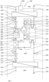
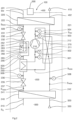
- the vapor compression system can optionally be equipped with a changeover valve, as a four-way valve or with a changeover device consisting of several valves or actuating units, as described in the Figures 1 , 2 , 3 and 4
- the switching valve switches the vapor compression system between a heating mode and a cooling mode.
- the switching valve is located downstream of the compressor in the high-pressure flow direction.
- the refrigerant at the intermediate pressure ZD flows after the first throttle element 230 to the refrigerant collector 260 and enters the refrigerant collector 260 through a first collector connection 261.
- a liquid volume 264 or a mass of refrigerant can accumulate at a variable level 263.
- Refrigerant collects or remains in the refrigerant collector 260, preferably with a liquid phase and an associated volume or mass and/or a partially gaseous phase above the liquid phase.
- the liquid refrigerant flows out of the refrigerant collector 260 again through the recuperator 250.
- a first intermediate pressure refrigerant temperature T ZDeZD is measured with a fifth temperature sensor 505 and after the recuperator 250, a second intermediate pressure refrigerant temperature T ZDz is measured with a sixth temperature sensor 506 and sent to the controller 500 via bus 560.
- the refrigerant still at the intermediate pressure ZD, now flows into the second throttle element 235, which is operated as a low-pressure throttle element in heating mode.
- the second throttle element 235 has a third throttle connection 236 and a fourth throttle connection 237.
- the refrigerant is expanded to the low pressure ND in heating mode, flows further in a low-pressure flow direction S ND into the second heat exchanger 240, which is operated as an evaporating heat exchanger in heating mode, absorbs energy, and evaporates—a cycle in the vapor compression system 200 is closed.
- the vapor compression system 200 is switched to a cooling mode by means of the switching valve 270.
- the refrigerant at high pressure HD flows in the high pressure flow direction S HD from the compressor 210 to the switching valve 270 and from there in a high pressure cooling flow direction S HDK to the second heat exchanger 240, which is operated as a condensing heat exchanger in the cooling mode.
- Heat, in this cooling mode this is the source energy Q Q , is transferred from the refrigerant to the heat source system 300 in the second heat exchanger 240.
- an air-water heat pump energy is thus transferred to the air, and in a brine-water heat pump, energy is transferred to the brine.
- the refrigerant is expanded from the high pressure HD to the intermediate pressure ZD in the second throttle element 235, which is operated as an intermediate pressure throttle element by the controller 500 in the cooling mode.
- the refrigerant at the intermediate pressure ZD flows through the high-pressure path of the intermediate heat exchanger 250 and then through the refrigerant collector 260 to the first throttle device 230, which in cooling mode is operated by the controller 500 as a low-pressure throttle device and where the refrigerant is further expanded to the low pressure ND.
- the refrigerant flows on to the first heat exchanger 220, which in cooling mode is operated as an evaporating heat exchanger, and heat energy Q H is absorbed by the heat sink system 400.
- the heat energy Qh is transferred from the refrigerant to the heat source medium.
- heat source medium is more advantageously used to describe the medium from which energy is transferred to the refrigerant circuit as a heat source.
- heat is extracted from the house's heating system and transferred to the refrigerant.
- a first opening of a first tube 265 and a second opening 266 of a second tube are arranged at the same level in the collector. Thus, refrigerant is introduced and discharged at the same level in both cooling and heating modes.
- the openings of the pipes are preferably arranged at a low height
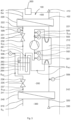
- Fig. 3 shows one, largely to the in Fig. 1
- the vapor compression cycle 200 described in the heating mode is similar to the one described above, with the intermediate heat exchanger 250 integrated into the refrigerant receiver 260.
- the intermediate heat exchanger 250 is surrounded by liquid refrigerant in the refrigerant receiver 260 corresponding to the level 263.
- the recuperator 250 is advantageously immersed in the liquid refrigerant to the same level as the refrigerant level 263.
- the intermediate heat exchanger 250 here is the low-pressure refrigerant path of the "recuperator" or intermediate heat exchanger 250.
- the immersion depth of the low-pressure path of the intermediate heat exchanger 250 advantageously approximately equals the level of the high-pressure side of the intermediate heat exchanger 250, in particular if the low-pressure refrigerant path reaches to the bottom of the heat exchanger.
- the changeover valve 270 is set to heating.
- the possible option for a cooling mode is indicated by dashed arrows.
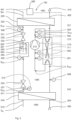
- This vapor compression system 200 is basically like the Fig. 1
- the vapor compression system 200 shown is constructed, but without an intermediate heat exchanger. Accordingly, a refrigerant collector 260 is arranged between the second throttle element 235 and the first throttle element 230, but no intermediate heat exchanger.
- the vapor compression system 200 can also be constructed without a switching valve 270. In this case, switching from a heating mode to a cooling mode is not possible, nor vice versa.
- the embodiment according to Fig. 5 shows the heating operating mode. Nevertheless, the vapor compression system 200 has a first throttle element 230, acting as an intermediate pressure throttle element, and a second throttle element 235, acting as a low pressure throttle element. Between the two throttle elements 230, 235, the refrigerant is maintained at the intermediate pressure ZD, a refrigerant pressure that is lower than the high pressure HD and higher than the low pressure ND.
- a reservoir, particularly for liquid refrigerant, is provided in a collector 260 at a level 263.
- the vapor compression system 200 without a switching valve 270 as a cooling system, i.e., in a non-reversible cooling mode. Switching from a cooling mode to a heating mode is not possible, nor vice versa.
- the vapor compression system 200 has a first throttle element 230, as a low-pressure throttle element, and a second throttle element 235, as an intermediate-pressure throttle element. Between the two throttle elements 230, 235, the refrigerant is kept at the intermediate pressure ZD, a refrigerant pressure that is lower than the high pressure (HP) and higher than the low pressure (LP).
- HP high pressure
- LP low pressure
- the compressor is connected with the flow direction "inverted" relative to the existing figures, and the sensor assignment must also be inverted or, equivalently, shifted accordingly.
- Figure 6 relates to the method for operating a heat pump (100) in heating mode with a vapor compression system (200) in which an at least partially gaseous refrigerant is compressed from the low pressure ND to the high pressure HD by a compressor (210) controlled by a controller (500).
- the first manipulated variable ES is determined for the first throttle element 230, which is flowed through in the high pressure flow direction S HD downstream of the first heat exchanger 220 and is designed and advantageously operated as an intermediate pressure throttle element, as a function of a subcooling deviation Ua of an actual subcooling value Ui from a target subcooling value Us of the refrigerant at an outlet of the first heat exchanger 220.
- the subcooling value Ui is determined at least with the aid of the third temperature sensor 509, wherein a temperature measurement value measured with the third temperature sensor 509 is at least one input variable for measuring or determining the subcooling value Ui and advantageously a further input variable is a boiling temperature T HD calculated from the high pressure.
- a second manipulated variable ZS for the first throttle element 230, through which flow takes place downstream of the first heat exchanger 220 as a liquefied heat exchanger in the refrigerant flow direction, is determined as a function of at least one process value PW of the vapor compression system 200, which is processed in a stored calculation model to form the second manipulated variable ZS.
- Figure 6 shows a unit 530 of the controller 500, which records measured variables MG such as the high pressure HD, a low pressure ND, a compressor speed, or another measured variable MG by means of a determination device EP for measured variables MG or process values PW, which are then fed into a computing unit 540 via a feed device ER. Furthermore, in the exemplary embodiment, the target subcooling Us is advantageously transmitted to the computing unit 540.
- measured variables MG such as the high pressure HD, a low pressure ND, a compressor speed, or another measured variable MG by means of a determination device EP for measured variables MG or process values PW, which are then fed into a computing unit 540 via a feed device ER.
- the target subcooling Us is advantageously transmitted to the computing unit 540.
- the second manipulated variable ZS is determined from the fed-in measured values or measured variables MG and advantageously also the target subcooling.
- the intermediate pressure ZD is lower than the high pressure HD, and the refrigerant at the intermediate pressure ZD is fed to the refrigerant collector 260. From here, i.e., from the refrigerant state "4," further expansion to the low pressure ND occurs in the second throttle element 235. The refrigerant is then fed at the low pressure ND to the second heat exchanger 240, the evaporating heat exchanger, where the refrigerant evaporates approximately isobarically and is advantageously superheated, from "5" to "1.” Ideal, complete isobaric evaporation is rarely achieved in reality, since a pressure drop of up to one bar in the evaporator can sometimes occur due to undesired throttling.
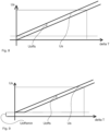
- Fig. 8 The x-axis shows a temperature difference of the heat sink medium, i.e., the heat transfer medium temperature difference delta T, and the y-axis shows the calculated target subcooling Us. Furthermore, an offset subcooling value U offs is shown as an advantageous parallel shift.
- a minimum limitation for the target subcooling thus a minimum offset subcooling value U offsmin , is provided, which in the exemplary embodiment is advantageously limited to 1 K.
Landscapes
- Engineering & Computer Science (AREA)
- Physics & Mathematics (AREA)
- Mechanical Engineering (AREA)
- Thermal Sciences (AREA)
- General Engineering & Computer Science (AREA)
- Compression-Type Refrigeration Machines With Reversible Cycles (AREA)
Applications Claiming Priority (1)
| Application Number | Priority Date | Filing Date | Title |
|---|---|---|---|
| DE102023136084.1A DE102023136084A1 (de) | 2023-12-20 | 2023-12-20 | Verfahren zum Betrieb einer Wärmepumpe mit einem Dampfkompressionssystem |
Publications (1)
| Publication Number | Publication Date |
|---|---|
| EP4579145A1 true EP4579145A1 (fr) | 2025-07-02 |
Family
ID=93655935
Family Applications (1)
| Application Number | Title | Priority Date | Filing Date |
|---|---|---|---|
| EP24215454.0A Pending EP4579145A1 (fr) | 2023-12-20 | 2024-11-26 | Pompe à chaleur et procédé de fonctionnement d'une pompe à chaleur dotée d'un système de compression de vapeur |
Country Status (2)
| Country | Link |
|---|---|
| EP (1) | EP4579145A1 (fr) |
| DE (1) | DE102023136084A1 (fr) |
Citations (7)
| Publication number | Priority date | Publication date | Assignee | Title |
|---|---|---|---|---|
| JP2003139382A (ja) * | 2001-10-31 | 2003-05-14 | Mitsubishi Electric Corp | 空気調和機 |
| EP1965158A2 (fr) * | 2007-03-02 | 2008-09-03 | STIEBEL ELTRON GmbH & Co. KG | Procédé destiné au calibrage d'une installation de refroidissement et installation de refroidissement |
| CN103486691B (zh) * | 2013-09-17 | 2015-09-30 | 青岛海信日立空调系统有限公司 | 多联机空调系统的制冷剂流量控制方法和装置 |
| DE10103150B4 (de) | 2001-01-24 | 2015-12-10 | Stiebel Eltron Gmbh & Co. Kg | Lüftungsanlage |
| EP2664868B1 (fr) | 2012-05-15 | 2021-03-17 | Stiebel Eltron GmbH & Co. KG | Dispositif de pompe à chaleur et évaporateur pour un dispositif de pompe à chaleur |
| US20220106513A1 (en) * | 2019-06-19 | 2022-04-07 | Daikin Industries, Ltd. | Refrigerant-containing composition, use of same, refrigerator having same, operation method for said refrigerator, and refrigeration cycle device equipped with same |
| EP1965160B1 (fr) * | 2007-03-02 | 2022-05-25 | STIEBEL ELTRON GmbH & Co. KG | Procédé destiné à la commande d'une installation de refroidissement à compression et installation de refroidissement à compression |
Family Cites Families (2)
| Publication number | Priority date | Publication date | Assignee | Title |
|---|---|---|---|---|
| JP7069831B2 (ja) * | 2018-02-28 | 2022-05-18 | 株式会社富士通ゼネラル | 空気調和機 |
| JP7301230B2 (ja) * | 2020-06-19 | 2023-06-30 | 三菱電機株式会社 | 冷凍サイクル装置 |
-
2023
- 2023-12-20 DE DE102023136084.1A patent/DE102023136084A1/de active Pending
-
2024
- 2024-11-26 EP EP24215454.0A patent/EP4579145A1/fr active Pending
Patent Citations (7)
| Publication number | Priority date | Publication date | Assignee | Title |
|---|---|---|---|---|
| DE10103150B4 (de) | 2001-01-24 | 2015-12-10 | Stiebel Eltron Gmbh & Co. Kg | Lüftungsanlage |
| JP2003139382A (ja) * | 2001-10-31 | 2003-05-14 | Mitsubishi Electric Corp | 空気調和機 |
| EP1965158A2 (fr) * | 2007-03-02 | 2008-09-03 | STIEBEL ELTRON GmbH & Co. KG | Procédé destiné au calibrage d'une installation de refroidissement et installation de refroidissement |
| EP1965160B1 (fr) * | 2007-03-02 | 2022-05-25 | STIEBEL ELTRON GmbH & Co. KG | Procédé destiné à la commande d'une installation de refroidissement à compression et installation de refroidissement à compression |
| EP2664868B1 (fr) | 2012-05-15 | 2021-03-17 | Stiebel Eltron GmbH & Co. KG | Dispositif de pompe à chaleur et évaporateur pour un dispositif de pompe à chaleur |
| CN103486691B (zh) * | 2013-09-17 | 2015-09-30 | 青岛海信日立空调系统有限公司 | 多联机空调系统的制冷剂流量控制方法和装置 |
| US20220106513A1 (en) * | 2019-06-19 | 2022-04-07 | Daikin Industries, Ltd. | Refrigerant-containing composition, use of same, refrigerator having same, operation method for said refrigerator, and refrigeration cycle device equipped with same |
Also Published As
| Publication number | Publication date |
|---|---|
| DE102023136084A1 (de) | 2025-06-26 |
Similar Documents
| Publication | Publication Date | Title |
|---|---|---|
| EP3816543B1 (fr) | Procédé de régulation d'un détendeur | |
| EP4065908A1 (fr) | Appareil de réfrigération ayant un compartiment qui peut être utilisé d'une manière variable | |
| DE112019007078T5 (de) | Klimagerät | |
| EP3730873B1 (fr) | Procédé de fonctionnement d'une pompe à chaleur dotée d'un système de compression de vapeur | |
| DE102007010645A1 (de) | Verfahren zum Steuern einer Kompressionskälteanlage und eine Kompressionskälteanlage | |
| EP2526353B1 (fr) | Procédé de commande et de réglage de pompes à chaleur et d'installations réfrigérantes | |
| EP3922926B1 (fr) | Procédé de régulation d'un processus de dégivrage d'un évaporateur d'une installation de réfrigération à compression et installation de réfrigération à compression | |
| EP3922931B1 (fr) | Installation de réfrigération à compression et procédé de fonctionnement de celle-ci | |
| EP3922932B1 (fr) | Procédé de fonctionnement d'une installation de réfrigération à compression et installation de réfrigération à compression | |
| DE102020115270A1 (de) | Verfahren und Vorrichtung zum Regeln eines Kältekreislaufs | |
| EP3640565A1 (fr) | Régulation de la puissance optimale cop | |
| DE102012208819A1 (de) | Verfahren für die steuerung und regelung von kälteanlagen und wärmepumpen mit luftbeaufschlagtem verdampfer | |
| EP4579145A1 (fr) | Pompe à chaleur et procédé de fonctionnement d'une pompe à chaleur dotée d'un système de compression de vapeur | |
| EP3922925B1 (fr) | Procédé de fonctionnement d'une installation de réfrigération à compression et installation de réfrigération à compression | |
| EP3922929B1 (fr) | Procédé de régulation d'une installation de réfrigération à compression et installation de réfrigération à compression | |
| DE102020122713B4 (de) | Verfahren zum Betreiben einer Wärmepumpe | |
| EP3922933B1 (fr) | Procédé de régulation d'une installation de réfrigération à compression et installation de réfrigération à compression | |
| DE102007039296A1 (de) | Wärmepumpenanlage | |
| DE202006014246U1 (de) | Kaltdampf-Kältemaschine | |
| EP4495504B1 (fr) | Circuit de réfrigérant et pompe à chaleur | |
| EP3922930B1 (fr) | Procédé de fonctionnement d'une installation de réfrigération à compression et installation de réfrigération à compression associée | |
| EP4575353A1 (fr) | Circuit de refroidissement de pompe à chaleur et pompe à chaleur | |
| DE102023136083A1 (de) | Verfahren und entsprechend ausgebildete Vorrichtung zum Regeln eines Kältekreislaufs sowie Kompressionskälteanlage | |
| EP2212633A2 (fr) | Procédé et dispositif de régulation électronique pour des installations frigorifiques |
Legal Events
| Date | Code | Title | Description |
|---|---|---|---|
| PUAI | Public reference made under article 153(3) epc to a published international application that has entered the european phase |
Free format text: ORIGINAL CODE: 0009012 |
|
| STAA | Information on the status of an ep patent application or granted ep patent |
Free format text: STATUS: THE APPLICATION HAS BEEN PUBLISHED |
|
| AK | Designated contracting states |
Kind code of ref document: A1 Designated state(s): AL AT BE BG CH CY CZ DE DK EE ES FI FR GB GR HR HU IE IS IT LI LT LU LV MC ME MK MT NL NO PL PT RO RS SE SI SK SM TR |
|
| STAA | Information on the status of an ep patent application or granted ep patent |
Free format text: STATUS: REQUEST FOR EXAMINATION WAS MADE |
|
| 17P | Request for examination filed |
Effective date: 20260102 |