EP4579170A1 - Extension motorisée pour support de fusil bipode - Google Patents
Extension motorisée pour support de fusil bipode Download PDFInfo
- Publication number
- EP4579170A1 EP4579170A1 EP24223689.1A EP24223689A EP4579170A1 EP 4579170 A1 EP4579170 A1 EP 4579170A1 EP 24223689 A EP24223689 A EP 24223689A EP 4579170 A1 EP4579170 A1 EP 4579170A1
- Authority
- EP
- European Patent Office
- Prior art keywords
- telescopic
- telescopic portion
- actuator
- gun
- extension system
- Prior art date
- Legal status (The legal status is an assumption and is not a legal conclusion. Google has not performed a legal analysis and makes no representation as to the accuracy of the status listed.)
- Pending
Links
Images











Classifications
-
- F—MECHANICAL ENGINEERING; LIGHTING; HEATING; WEAPONS; BLASTING
- F41—WEAPONS
- F41A—FUNCTIONAL FEATURES OR DETAILS COMMON TO BOTH SMALLARMS AND ORDNANCE, e.g. CANNONS; MOUNTINGS FOR SMALLARMS OR ORDNANCE
- F41A23/00—Gun mountings, e.g. on vehicles; Disposition of guns on vehicles
- F41A23/02—Mountings without wheels
- F41A23/04—Unipods
- F41A23/06—Unipods adjustable
-
- F—MECHANICAL ENGINEERING; LIGHTING; HEATING; WEAPONS; BLASTING
- F41—WEAPONS
- F41A—FUNCTIONAL FEATURES OR DETAILS COMMON TO BOTH SMALLARMS AND ORDNANCE, e.g. CANNONS; MOUNTINGS FOR SMALLARMS OR ORDNANCE
- F41A23/00—Gun mountings, e.g. on vehicles; Disposition of guns on vehicles
- F41A23/02—Mountings without wheels
- F41A23/08—Bipods
- F41A23/10—Bipods adjustable
-
- F—MECHANICAL ENGINEERING; LIGHTING; HEATING; WEAPONS; BLASTING
- F41—WEAPONS
- F41A—FUNCTIONAL FEATURES OR DETAILS COMMON TO BOTH SMALLARMS AND ORDNANCE, e.g. CANNONS; MOUNTINGS FOR SMALLARMS OR ORDNANCE
- F41A23/00—Gun mountings, e.g. on vehicles; Disposition of guns on vehicles
- F41A23/02—Mountings without wheels
- F41A23/12—Tripods ; Mountings having at least three legs
- F41A23/14—Tripods ; Mountings having at least three legs adjustable
-
- F—MECHANICAL ENGINEERING; LIGHTING; HEATING; WEAPONS; BLASTING
- F41—WEAPONS
- F41A—FUNCTIONAL FEATURES OR DETAILS COMMON TO BOTH SMALLARMS AND ORDNANCE, e.g. CANNONS; MOUNTINGS FOR SMALLARMS OR ORDNANCE
- F41A23/00—Gun mountings, e.g. on vehicles; Disposition of guns on vehicles
- F41A23/56—Arrangements for adjusting the gun platform in the vertical or horizontal position
-
- F—MECHANICAL ENGINEERING; LIGHTING; HEATING; WEAPONS; BLASTING
- F41—WEAPONS
- F41C—SMALLARMS, e.g. PISTOLS, RIFLES; ACCESSORIES THEREFOR
- F41C23/00—Butts; Butt plates; Stocks
- F41C23/04—Folding or telescopic stocks or stock parts
-
- F—MECHANICAL ENGINEERING; LIGHTING; HEATING; WEAPONS; BLASTING
- F41—WEAPONS
- F41C—SMALLARMS, e.g. PISTOLS, RIFLES; ACCESSORIES THEREFOR
- F41C23/00—Butts; Butt plates; Stocks
- F41C23/14—Adjustable stock or stock parts, i.e. adaptable to personal requirements, e.g. length, pitch, cast or drop
Definitions
- the invention relates to the field of mountings of firearms including locking means between gun and mounting, mountings without wheels (conventional mono-, bi- or tripods, test mounts and bench rests).
- Rifle supports such as bipods
- bipods have long been used to steady the muzzle of a rifle or shotgun during the firing thereof in an effort to "stabilize” the weapon to increase the shooter's accuracy. If the bipod is directly attached to the barrel of the gun, the harmonics of the barrel during the firing are materially affected by the bipod. Interfering with the harmonics of the barrel unpredictably alters the projectile's exit from the muzzle causing irregularities in the final trajectory of the projectile.
- the harmonics of the barrel during firing is not affected, but the lever arm between the point of bipod attachment to the toe of the stock and the muzzle leads to a mechanically amplified displacement of the muzzle orientation for any unintended biological input or unintended movement during aiming or firing, materially affecting the accuracy of the rifle system as operated by the shooter.
- Accuracy of aiming and firing depends not only on the angular orientation in space of the gun barrel, but also on the stability of the gun muzzle position in space and the ability of the shooter to minimize the effects of biological input and unintended movement on the abovementioned components as a whole.
- the illustrated embodiments of the present disclosure provide an extension system for a gun support, the gun having a barrel with an effective muzzle.
- the extension system may include a telescopic assembly which has a proximal end and a distal end.
- the telescopic assembly may include a first telescopic portion and second telescopic portion, an actuator that is configured to selectively adjust a horizontal displacement of the second telescopic portion relative to the first telescopic portion, and means for rotating the distal end of the telescopic assembly relative to the second telescopic portion.
- the gun support may be coupled to the distal end of the telescopic assembly.
- the extension system may include a chassis that is configured to accommodate the telescopic assembly.
- the actuator that may be configured to selectively adjust a horizontal displacement of the second telescopic portion relative to the first telescopic portion may include an extendable piston disposed therein.
- a proximal end of the actuator may be coupled to a proximal end of the first telescopic portion, while a distal end of the extendable piston may be coupled to a distal end of the second telescopic portion.
- the extension system may also include a battery that may be removably coupled to the chassis and electrically communicated to the actuator.
- the means for rotating the distal end of the telescopic assembly relative to the second telescopic portion may include a front plug which extends beyond a distal end of the second telescopic portion, a plug adapter that is disposed within the second telescopic portion and inserted into the front plug, and a set screw that is disposed through an aperture defined in the front plug and engaged with the plug adapter.
- the gun support may be coupled to the front plug.
- rotating a front plug selectively coupled to the gun support may include rotating the front plug about a plug adapter coupled to a distal end of a piston, wherein a proximal end of the piston is disposed within the actuator.
- rotating the front plug about a plug adapter may include disposing a set screw through the front plug and into a channel defined around a circumference of the plug adapter, and then traversing the set screw through the channel as the front plug is rotated about the plug adapter.
- selectively activating an actuator disposed within a telescopic assembly and selectively deactivating the actuator when the second telescopic portion has reached a second horizontal position relative to the first telescopic portion may include actuating a switch that is coupled to the actuator.
- the method may also include selectively locking the second telescopic portion into position at the second horizontal position relative to the first telescopic portion.
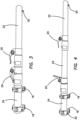
- Fig. 3 is a side elevational view of the extension system 14 of the illustrated embodiments shown in the partially contracted configuration in isolation of connection to the bipod support 12 or gun stock's distal end 16.
- extension tubes 22 are selectively locked into position using conventional toggle clamps 20.
- one toggle clamp 20 is fixed to end portion 24 and the second toggle clamp 20 is fixed to the distal end of the first extension tube 22.
- FIG. 4 is a side elevational view of the extension system 14 of the illustrated embodiments shown in the fully extended configuration in isolation of connection to the bipod support 12 or gun stock 16.
- Fig. 4 shows the first toggle clamp 20 on the left in the figure unlocked allowing first extension tube 22 on the left to extend from proximal end portion 24.
- the second toggle clamp 20 on the right in the figure is in the locked position holding the second and distal-most extension tube 22 in the right of the figure in position.
- Fig. 16 is a side plan view of a second embodiment of the extension system 14 shown in isolation from the gun 10 with a folding forward grip 23 attached to proximal end portion or base tube 24 of extension system 14 by means of a floating ring 21 and with a short distal Picatinny rail 38.
- the embodiment of Fig. 16 includes a single toggle clamp 20 and extension tube 22.
- Fig. 17 is a side plan view of an embodiment of Fig. 16 shown in a collapsed configuration
- Fig. 18 is a side plan view of an embodiment of Fig. 16 shown in an extended configuration with folding grip 23 extended in an operative position.
- locking clamp 20 is pulled into its open configuration. This releases the telescopic feature of extension system 14 and allows the resting point of extension system 14 to be selectively chosen by the user. In the preferred embodiment, the resting point being at, near or in front of the effective muzzle exit of gun 10 .
- Perturbative reorientations or translations of the gun barrel 74 from all possible sources can be characterized as a change in angular orientation of the gun barrel 74.
- These perturbations can be characterized as a finite distance of movement at the butt or toe of the gun 10 resulting in a change in the angular orientation of the gun 10 during firing, which finite distance will be different for each shooter and gun 10 and even each firing for a given shooter and gun 10.
- the amount of angular perturbation translated to the gun barrel 74 depends on the geometry defined by the size of the gun 10 from the toe to the pivot or support point of the support or bipod 12.
- the cone of fire will then depend on the range to the target and the average angular perturbation of the gun barrel 74. It is desirable to have the cone of fire as small as possible.
- the cone of fire can be changed by changing the pivot point or support point of the gun 10 support relative to the toe of the gun 10 and hence the muzzle 76. It has been discovered that the ratio of two cones of fire with different pivot points for a given perturbation will depend inversely on the ratio of the distances from the toe to the pivot points corresponding to the respective cones of fire and will be independent of the range to the target. For example, doubling the distance from the toe of the gun 10 to the pivot point of the bipod support 12 will halve the cone of fire at the target.
- the increase of the distance from the toe of the gun 10 to the pivot point of the bipod support 12 is limited as a practical matter by the limitation in the rigidity of materials used, the size of the support accessory which can or is desirable to be carried by a shooter, and the ease of deployment of the bipod support 12.
- the locking clamp 20 is returned to the closed and locked position when tube 22 is extended to the desired length.
- the accurate and precise aiming and firing of a gun is a complex phenomenon dependent on multiple input variables which are not perfectly understood and which continue to be debated among experts.
- the stability of the gun and effective location of the gun muzzle at the moment the projectile exits the muzzle of the barrel affect precision and thus potential accuracy of the gun during each firing process.
- Fig. 5 is a side elevational view of the extension system 14 of the illustrated embodiments shown in the contracted configuration connected to a bipod gun mount 12 in its folded configuration in isolation from the gun 10.
- Bipod support 12 in the illustrated embodiment has spring-loaded adjustable length legs, but any bipod design desired may be employed.
- end portion 24 and extension tubes 22 are comprised of thick walled carbon fiber tubing, but any strong, rigid material may be equivalently employed.
- a pair of mounting rings 18 are clamped onto end portion 24 and include a conventional gun fitting 32 best seen in Fig. 7 on their upper portions, such as a Picatinny rail as shown in Fig. 1 attached to the gun stock 16. Locking is accomplished by tightening fitting bolts.
- Fig. 6 is a side elevational view of the proximal end portion 24 of the extension system 14 of the illustrated embodiments shown in enlarged view depicting the rear sliding toggle clamp 20 and the two mounting rings 18 for attachment to the gun stock.
- FIG. 7 is a side elevational view of the proximal end portion 24 of the extension system 14 of the illustrated embodiments shown in enlarged view depicting one of the mounting rings 18 detached from the proximal portion 24 and rotated for a better plan view of the conventional gun fitting 32.
- ring 18 can be positioned on proximal end portion in any desired angular orientation. Its relative angular orientation, once selected, is then fixed by tightening bolt 19 best seen in Fig. 7 . Similarly, once an angular orientation is selected, it can be changed by loosening bolts 19 on rings 18, rotating proximal portion 24 within rings 18 and then fixing the new angular orientation by retightening bolts 19.
- gun 10 when gun 10 is canted to the side, when for example, bipod support 12 is placed on a canted surface as shown in Fig. 15 or if the legs of bipod support 12 are unevenly adjusted for any purpose, the canted angular position of gun 10 can be corrected or adjusted.
- the canting also known by shooting enthusiasts as "swiveling", is adjusted by rotating the nested tubes 22. This is also much easier to accomplish than loosening and re tightening mounting rings 18. Under normal conditions the gun operator will affix and tighten the proximal end portion 24 of the extension system 14 to the stock's distal end 16 with mounting rings 18 only once.
- any further desired adjustments can be accomplished by simply loosening toggle clamps 20, making the adjustments by rotating extension tubes 22 with respect to each other and retightening clamps 20.
- This is possible because the nested tubes 22, besides extending and collapsing, also rotate in either direction relative to one another by any degree from 0 to 360° or more. This allows for "extreme canting".
- Fig. 8 is an end perspective view of the proximal end portion 24 of the extension system 14 of the illustrated embodiments shown in enlarged view depicting an end plug 34 for closing the proximal end portion 24.
- End plug 34 is compression fit into the proximal end of end portion 24, but threaded, glued or pinned plugs could also be utilized.
- Fig. 9 is a bottom elevational view of the distal end of extension tube 22 of the extension system 14 of the illustrated embodiments shown in enlarged view depicting the threaded mounting holes 36 and mounting screw 30 shown as detached by which different versions of the bipod support 12 will be coupled to the extension system 14.
- Fig. 10 is a partial bottom elevational view of the distal end of extension tube 22 of the extension system 14 of the illustrated embodiments shown in enlarged view depicting the installed sling swivel stud mounting screw 30.
- a more modern alternative mounting method to the sling swivel stud mounting screw 30 is the Picatinny rail attachment system 38 shown as detached in perspective view.
- Sling swivel stud mounting screw 30 is selectively installed in anyone of the threaded holes 36 in extension tube 22 and a sling swivel stud mounting type of bipod can be attached to it, as shown in Figure 5 .
- the sling swivel stud mounting screw 30 can be removed to allow for the attachment of a Picatinny rail 38 to which a Picatinny rail type of bipod, or most any Picatinny rail type accessory could attach, as shown in Fig. 13 .
- Picatinny rail attachment system 38 attaches to tube 22 by two through-bolts 40 threaded into the end holes 36 as best depicted in Fig. 11.
- Fig.12 is a partial bottom elevational view of the distal end portion of the extension system 14 with Picatinny rail 38 of the illustrated embodiments shown in enlarged view depicting the Picatinny rail attachment system 38 with the mating mounting fixture 42 of the bipod support 12 shown as detached.
- Fig.13 is a side elevational view of the distal end portion of the extension system 14 of the illustrated embodiments shown in enlarged view depicting the installed bipod support 12 coupled to Picatinny rail attachment system 38.
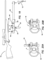
- Fig. 19 is a side plan view of the embodiment of Fig. 16 in exploded view being attached or mounted to a gun 10 using a tilted Picatinny rail 48 and a bipod 12.
- FIG. 20a is a perspective view of the quick detach mounting ring 18 in an unlocked configuration where toggle lever 19 is rotated to an open configuration releasing mounting ring 18 from tilted Picatinny rail 48.
- Fig. 20b is a perspective view of the quick detach mounting ring 18 in a locked configuration where toggle lever 19 is rotated to a closed configuration locking mounting ring 18 to tilted Picatinny rail 48.
- the attachment of Picatinny rail 48 to the gun stock 16 is better illustrated in the side plan elevational view of Fig. 25 .
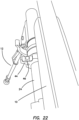
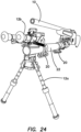
- Figs. 23 and 24 illustrate another embodiment where two bipods 12a and 12b are fixed to the distal end of extension system 14.
- Fig. 23 is a perspective view of an embodiment of the extension system 14 where two differently sized bipods 12a and 12b are attached to the distal end of the extension system 14 with the upper bipod 12a in a folded or collapsed configuration and the lower bipod 12b extended.
- Fig. 24 is a perspective view of the embodiment of Fig. 23 with the two bipods 12a and 12b rotated by a 180° rotation of the distal end of the extension system 14 to reverse the positions of the bipods 12a and 12b, the upper bipod 12a of Fig. 23 now shown as lowermost and extended and the lower bipod 12b of Fig. 23 now shown as uppermost and folded into a collapsed configuration.
- the effective position of muzzle 76 from the viewpoint of minimization of movement may not be at the anticipated physical location of muzzle 76, the exit orifice of gun 10, but may be at a slightly different longitudinal position according to the effect of a projectile fired through barrel 74. This in turn could depend very subtly on the rifling in barrel 74 and the nature of the projectile.
- Fig. 29 illustrated the ability to fine tune the position of bipod support 12 relative to muzzle 76 to obtain minimization of effect of unintended movement.
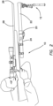
- Fig. 29 illustrates how the embodiment of this Figure is able to position bipod support 12 laterally physically closer to muzzle 76 than in the embodiment of Fig. 2 where the bipod extension 14 is mounted exterior to stock 16 of gun 10.
- Fig. 30 is a side elevational view of the gun 10 of Fig. 28 in which the telescopic bipod extension 80 has been deployed from the fore-end 78 of the gun 10 to place the bipod support 12 in front of the muzzle 76 of the gun 10.
- body 84 integrally extends into a bracket 92, shown in cross sectional view in Fig. 34 , which is bolted or screwed into receiver 70 as best seen in Fig. 30 .
- Body 84 is provided with a plurality of cavities 94 on or in its exposed exterior surfaces to form a modular lock (M-LOK) firearm rail interface system developed by Magpul Industries for direct accessory attachment onto the "negative space" (hollow slot) mounting points.
- M-LOK modular lock
- fore-end 78 could also be modified to provide mounting surfaces using other types of mounting systems, such as KeyMod system or Picatinny rail systems.
- portion 82 surrounds, but does not support, touch nor is it connected to barrel 74.
- Barrel 74 is left free-floating in integral bracket portion 82 so that harmonic or vibrational reverberations of barrel 74 during firing is unaffected by integral bracket portion 82.
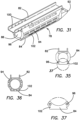
- Fig. 32 is a top plan view of the fore-end 78 of Fig. 31 and clearly shows the extension of integral channel 82 beyond body 84.
- This extension of integral channel 82 and the adjacent portion of it are provided with a plurality of through-holes 100, which provided additional means for mounting accessories adjacent to barrel 74, such as, but not limited to, clip on night vision equipment (not shown).
- These mounting holes 100 are best seen in Fig. 33 which is a side plan view of the fore-end 78 of Fig. 31 .
- Fig. 34 is a longitudinal cross sectional view of the fore-end 78 of Fig. 31 as seen through sections lines A - A of Fig. 32 and clearly shows the definition of cylindrical cavity 86 in body 84 for receiving first extension tube 88.
- Fig. 31 The end of body 84 is shown in Fig. 31 as being provided with four threaded bores 96 for mounting a body clamp 98 as best shown in Fig. 39 .
- Fig. 35 is an end plan view of the fore-end 78 of Fig. 31 clearly showing the mounting holes 96 for clamp 98.
- Fig. 38 is an isometric view of a clamp 98 that mounts to the fore-end 78 of Fig. 31 for selectively locking the first extension tube 88 therein.
- Fig. 39 is an end plan view of the clamp 98 of Fig. 38.
- Fig. 40 is a side plan view of the clamp 98 of Fig. 38.
- Fig. 41 is a perpendicular cross sectional view of the clamp 98 of Fig. 38 as seen through section lines A - A of Fig. 40 .
- Clamp 98 includes an integral base 104 into which four boreholes 106 have been defined aligned with threaded holes 96 in fore-end 78 and through which clamp 98 is screwed or bolted to fore-end 78.
- the top of clamp 98 is provided with an eccentric toggle lever 108, which is used to tighten clamp 78 around first extension tube 88 by rotating lever 108 into the position seen in Figs. 37 - 40 when tube 88 is inserted through clamp 98.
- the body of clamp 98 is comprised of two resilient circular opposing sides 99 separated by a gap 110 best seen in Figs. 38 and 40 .
- An adjustment bolt 112 is disposed through two opposing through holes in the top extended end 114 of clamp 98, through a slot 116 defined in the eccentric lobe 116 of lever 108 as shown in Fig. 38 .
- the threaded distal end 118 of bolt 112 is threaded into a threaded bore 120 defined perpendicularly through a cylindrical spindle 122 which serves as the pivot pin for lever 108.
- spindle 122 is positioned relative to top extended end 114 and the opposing surface thereof against which the eccentric of lever 108 rotates. In this manner the degree of locking and tightness of lever 108 is selectively adjusted when lever 108 is rotated thereby forcing the two opposing sides of top extended end 114 of clamp 98 together. As shown in Figs.
- a second clamp 126 is disposed on the distal end of tube 88 and is used to tighten or lock distal extension tube 90 to tube 88, when tube 90 is telescopically disposed into tube 88.
- Clamp 126 is a conventional tube clamp and therefore will not be further described, but is generally similar in operation to clamp 98.
- Tube 88 in turn is telescopically disposed into fore-end 78.
- FIG. 42 is a perspective view of the extension system 200 comprising a first tube 202 and a second tube 204 shown in a contracted configuration in isolation of connection to the bipod support 12 or gun stock's distal end 16.
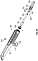
- Fig. 43 is an exploded view of the extension system 200 with the first and second tubes 202, 204 removed to better illustrate the components therein.
- a back plug 206 coupled to an internal portion of a proximal end of the first tube 202 is a back plug 206 while a floating ring 208 is in turn coupled an external portion of the proximal end of the first tube 202.
- the floating ring 208 comprises a rail 210 or other coupling means configured to accommodate a battery pack rail mount 212.
- the battery pack rail mount 212 comprises a thumb screw or other means for coupling onto the rail 210 of the floating ring 208.
- a battery 214 is in turn coupled to the battery pack rail mount 212.
- a rocker switch 216 or other actuation means is coupled to the battery 214.
- the rocker switch 216 upon actuation of the rocker switch 216 in a first direction, power is directed from the battery 214 to the motor 222 disposed in the actuator 220 via an electrical connection 218 disposed through the back plug 206.
- the motor 222 then drives the extendable driver or piston 224 in the distal direction towards the barrel 74 of the gun 10. Because the extendable driver or piston 224 is coupled to the plug adapter 226, the plug adapter 226 and the front plug 230 coupled thereto are also driven in the distal direction as seen in Figs. 45A and 45B .
- the second tube 204 extends or telescopically expands from the first tube 202 which remains in a stationary or static position relative to the gun 10.
- the support adapter or platform 236 disposed on the front plug 230, and any bipod support 12 coupled thereto or disposed thereon, is in turn likewise driven or moved forward in the distal direction.
- the user ceases activation of the motor 222 via appropriate actuation of the rocker switch 216.
- the user locks the position of the second tube 204 and the bipod support 12 relative to the first tube 202 by appropriate tightening of the toggle clamp 240.
- the toggle clamp 240 is released which then allows for the relative lateral movement of the second tube 204 according to the orientation of the actuated rocker switch 216.
- the set screw 234 comprises a head portion 248 and a threaded portion 246 and is inserted into the selected annular groove 242 with the head portion 248 resting or supported by a shoulder 250 defined within the annular groove 242 while the threaded portion 246 is inserted through the thickness of the front plug 230 and into a channel 244 circumferentially defined around the plug adapter 226.
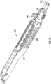
- FIG. 47 is a perspective view of the extension system 300 comprising a first tube 302 and a second tube 304 shown in a contracted configuration within a chassis 301 portion of the gun 10.
- Fig. 48 is an exploded view of the extension system 300 with the first and second tubes 302, 304 removed to better illustrate the components therein.
- a back plug 306 coupled to an internal portion of a proximal end of the first tube 202 is a back plug 306 while a battery 314 is in turn coupled or electronically communicated to the back plug 306, both the back plug and the battery 314 being held within an internal portion or compartment of the chassis 301.
- a battery door 318 is removably coupled to an underside or bottom portion of the chassis 301 to allow the user access to the battery 314 disposed therein.
- a rocker switch 316, button, or other actuation means is disposed in the chassis 301 and coupled to the battery 314.
- an actuator 320 comprising a motor 322 or other actuation means is disposed within the first tube 302 and electrically coupled or communicated to the back plug 306.
- the actuator 320 comprises an extendable driver or piston 324 which is selectively extended via activation of the motor 322. Coupled to a distal end of the extendable driver 324 via a pin 328 or other coupling means is a plug adapter 326.
- the plug adapter 326 in certain embodiments is disposed within or coupled to a front plug 330.
- a set screw 334 is disposed through an aperture defined in the front plug 330 and is configured to be inserted or disposed into a channel 332 defined around a circumference of the plug adapter 326 as is detailed further below.
- Disposed on a distal end of the front plug 330 is an support adapter or platform 336 that is specifically shaped to removably couple to or otherwise cooperate with the bipod support 12.
- the two telescopically nested tubes 302, 304 are nested within each other, although only the first tube 302 is observable through the openings defined in the chassis 301 in the depiction of Fig. 47 .
- the extension system 300 is disposed within an internal portion of the body of the chassis 301.
- the chassis 301 is configured to accommodate the barrel 74 of the gun 10 and to seamlessly integrate with the gun stock 16 and any other portion of the gun 10 as is known in the art.
- a toggle clamp 340 is fixed to a distal end portion of the first tube 302.
- the toggle clamp 340 comprises a cam lock and/or a thumb screw to selectively lock the position of the second tube 304 relative to the first tube 302
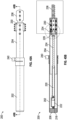
- Figs. 50A and 50B is a simplified top down view and a side elevational cross sectional view, respectively, of the distal end of the extension system 300 of the illustrated embodiments shown in the fully contracted configuration in isolation of connection to the chassis 301.
- Figs. 51A and 51B is a simplified top down view and a side elevational cross sectional view, respectively of the distal end of the extension system 300 of the illustrated embodiments shown in the fully expanded configuration while disposed or accommodated within the chassis 301.
- the rocker switch 316 upon actuation of the rocker switch 316 in a first direction, power is directed from the battery 314 to the motor 322 disposed in the actuator 320 via an electrical connection through the back plug 206.
- the motor 322 then drives the extendable driver or piston 324 in the distal direction towards the barrel 74 of the gun 10. Because the extendable driver or piston 324 is coupled to the plug adapter 326, the plug adapter 326 and the front plug 330 coupled thereto are also driven in the distal direction as seen in Figs. 49B , 51A, and 51B .
- the second tube 304 extends or telescopically expands from the first tube 302 which remains in a stationary or static position relative to the gun 10.
- the support adapter or platform 336 disposed on the front plug 330, and any bipod support 12 coupled thereto or disposed thereon, is in turn likewise driven or moved forward in the distal direction.
- the user ceases activation of the motor 322 via appropriate actuation of the rocker switch 316.
- the user locks the position of the second tube 304 and the bipod support 12 relative to the first tube 302 by appropriate tightening of the toggle clamp 340.
- the toggle clamp 340 is released which then allows for the relative lateral movement of the second tube 304 according to the orientation of the actuated rocker switch 316.
- actuation of the rocker switch 316, displacement of the bipod support 12 and the second tube 304, and tightening and releasing of the toggle clamp 340 are all done with a minimum of movement of the part of the user aiming the gun 10.
- a user lying in the prone position while aiming the gun 10 can adjust the placement of the bipod support 12 without having to stand or otherwise dramatically shift their body, allowing the user to maintain greater consistency between shots where adjustment of the bipod support 12 is needed.
- adjustment of the relative canted angle of the bipod support 12 and the front plug 330 coupled thereto is provided by the interaction between the set screw 334 and the plug adapter 326 as best seen in the magnified cross sectional view of Fig. 52 .
- the set screw 334 is disposed in one of a plurality of circular or annular grooves 342 defined around the circumference of the front plug 330.
- the set screw 334 comprises a head portion 348 and a threaded portion 346 and is inserted into the selected annular groove 342 with the head portion 348 resting or supported by a shoulder 350 defined within the annular groove 342 while the threaded portion 346 is inserted through the thickness of the front plug 330 and into a channel 344 circumferentially defined around the plug adapter 226.
- the threaded portion 346 of the set screw 334 is inserted or otherwise configured to be fitted loosely within the channel 344 of the plug adapter 326 so as to facilitate relative movement therebetween with a minimal amount of friction.
- the user when the user wishes to change the canted angle of the bipod support 12 coupled to the support adapter 336, the user rotates the bipod support 12 which in turn rotates the front plug 330 a corresponding amount.
- the set screw 334 rotates with it, specifically with the threaded portion 346 of the set screw 334 moving along the circumferential length of the channel 344 defined in the plug adapter 326.
- the bipod support 12 may be rotated in either direction without applying any torque to the plug adapter 326, the extendable piston 324, or the motor 322, all of which remain fixed during the adjustment of the bipod support 12.
- the front plug 330 rotates around the plug adapter 326, relative angular movement between the bipod support 12 and the first and second tubes 302, 304 is achieved without any further input required on the part of the user.
- the user may adjust the horizontal displacement of the bipod support 12 manually by pulling the second tube 202, 302, the front plug 230, 330, and/or the bipod support 12 itself until reaching the desired position.
- the placement of the bipod support 12 is then locked into position relative to the first tube 202, 302 via actuation of the toggle clamp 240, 340 as discussed above.
- the toggle clamp 240, 340 is released and the user then manually pushes or squeezes the second tube 202, 302, the front plug 230, 330, and/or the bipod support 12 itself against the first tube 202, 302 and/or the chassis 301 until the second tube 204, 304 is fully enveloped or accommodated within the first tube 202, 302 and/or chassis 301.
- the extension system 200, 300 comprises a hydraulic system disposed within the first tube 202 or chassis 301.
- the hydraulic system is removably coupled to the chassis 301, the extension system 200, 300, and/or another portion of the gun 10.
- the actuator 220, 320 is a hydraulic actuator comprising a hydraulic cylinder or piston, a reservoir, and a control valve configured to regulate the hydraulic fluid therein.
- the control valve increases pressure within the hydraulic actuator which extends the cylinder or piston, thereby extending the second tube 204, 304 and the bipod support 12 coupled thereto in a similar manner discussed above.
- the control valve is actuated so as to release pressure within the hydraulic actuator which compresses the cylinder or piston, thereby retracting the second tube 204, 304 and the bipod support 12 back in the proximal direction.
- the user can still manually extend and/or contract the telescopic extension system 200, 300 by pulling or pushing the bipod support 12 in the appropriate direction in the manner discussed above.
Landscapes
- Engineering & Computer Science (AREA)
- General Engineering & Computer Science (AREA)
- Toys (AREA)
Applications Claiming Priority (1)
| Application Number | Priority Date | Filing Date | Title |
|---|---|---|---|
| US202363615589P | 2023-12-28 | 2023-12-28 |
Publications (1)
| Publication Number | Publication Date |
|---|---|
| EP4579170A1 true EP4579170A1 (fr) | 2025-07-02 |
Family
ID=94128503
Family Applications (1)
| Application Number | Title | Priority Date | Filing Date |
|---|---|---|---|
| EP24223689.1A Pending EP4579170A1 (fr) | 2023-12-28 | 2024-12-30 | Extension motorisée pour support de fusil bipode |
Country Status (2)
| Country | Link |
|---|---|
| US (1) | US20250216167A1 (fr) |
| EP (1) | EP4579170A1 (fr) |
Citations (2)
| Publication number | Priority date | Publication date | Assignee | Title |
|---|---|---|---|---|
| EP3557178A1 (fr) * | 2018-04-17 | 2019-10-23 | Accuracy Solutions, LLC | Rallonge pour un support bipied inclus dans la crosse d'un pistolet |
| US20200378706A1 (en) * | 2018-02-19 | 2020-12-03 | Corner Shot (Israel) Ltd. | Variable-length corner shooting assembly |
Family Cites Families (8)
| Publication number | Priority date | Publication date | Assignee | Title |
|---|---|---|---|---|
| US6237462B1 (en) * | 1998-05-21 | 2001-05-29 | Tactical Telepresent Technolgies, Inc. | Portable telepresent aiming system |
| US8448561B2 (en) * | 2006-08-24 | 2013-05-28 | Raytheon Company | Weapon mount |
| US7895930B2 (en) * | 2007-01-23 | 2011-03-01 | Foster-Miller, Inc. | Weapon mount |
| WO2014124669A1 (fr) * | 2013-02-13 | 2014-08-21 | Steinert Sensing Systems AS | Support bipied pliable et réglable |
| PL3507563T3 (pl) * | 2016-09-01 | 2026-04-13 | Accuracy Solutions, Llc | Element wysuwany podpórki broni |
| US11713944B2 (en) * | 2020-12-31 | 2023-08-01 | Smart Shooter Ltd. | Dual mode weapon-mounted fire control system |
| US12104871B2 (en) * | 2021-10-06 | 2024-10-01 | Branden Cook Christiansen | Self-adjusting shooting rest |
| US12292249B2 (en) * | 2023-07-18 | 2025-05-06 | Accu-Tac LLC | Adjustable bipod |
-
2024
- 2024-12-27 US US19/003,850 patent/US20250216167A1/en active Pending
- 2024-12-30 EP EP24223689.1A patent/EP4579170A1/fr active Pending
Patent Citations (2)
| Publication number | Priority date | Publication date | Assignee | Title |
|---|---|---|---|---|
| US20200378706A1 (en) * | 2018-02-19 | 2020-12-03 | Corner Shot (Israel) Ltd. | Variable-length corner shooting assembly |
| EP3557178A1 (fr) * | 2018-04-17 | 2019-10-23 | Accuracy Solutions, LLC | Rallonge pour un support bipied inclus dans la crosse d'un pistolet |
Also Published As
| Publication number | Publication date |
|---|---|
| US20250216167A1 (en) | 2025-07-03 |
Similar Documents
| Publication | Publication Date | Title |
|---|---|---|
| US10718588B2 (en) | Extension for a bipod support gun support | |
| US6705037B2 (en) | Apparatuses and methods for mounting an optical device to an object | |
| US5628135A (en) | Shooting support for rifles and handguns | |
| US9835411B2 (en) | Integrated rail and sight system for firearm | |
| US4393614A (en) | Gun rest | |
| US20250224212A1 (en) | Ball head based clamping device | |
| US10571219B2 (en) | Forearm pistol brace | |
| US7401431B2 (en) | Trigger actuated stabilization device | |
| US10352644B2 (en) | Firearm stock with support | |
| US10900736B2 (en) | Retractable firearm support assembly | |
| US10921090B2 (en) | Mounting adapter for self-loading firearms | |
| US20080092423A1 (en) | Assault rifle back-up sight rib and support structure | |
| US20200173755A1 (en) | Multi-use block quick transitioning equipment support interface handguard | |
| US12292249B2 (en) | Adjustable bipod | |
| US4750269A (en) | Firearm sight-in device | |
| US20250216167A1 (en) | Motorized Extension for a Bipod Gun Support | |
| EP1026471A2 (fr) | Support pour armes à feu | |
| EP3557178B1 (fr) | Rallonge pour un support bipied inclus dans la crosse d'un pistolet | |
| US20100037760A1 (en) | Method and apparatus for muzzle lift compensation | |
| US20100275484A1 (en) | Rail mounted recoil system for the forend of a firearm | |
| AU2007200105A1 (en) | Platform for an opto-electronic supplementary aiming appliance | |
| RU2102682C1 (ru) | Противотанковый гранатомет | |
| WO2010062374A1 (fr) | Système de recul monté sur rail pour le fût d'une arme à feu |
Legal Events
| Date | Code | Title | Description |
|---|---|---|---|
| PUAI | Public reference made under article 153(3) epc to a published international application that has entered the european phase |
Free format text: ORIGINAL CODE: 0009012 |
|
| STAA | Information on the status of an ep patent application or granted ep patent |
Free format text: STATUS: THE APPLICATION HAS BEEN PUBLISHED |
|
| AK | Designated contracting states |
Kind code of ref document: A1 Designated state(s): AL AT BE BG CH CY CZ DE DK EE ES FI FR GB GR HR HU IE IS IT LI LT LU LV MC ME MK MT NL NO PL PT RO RS SE SI SK SM TR |
|
| STAA | Information on the status of an ep patent application or granted ep patent |
Free format text: STATUS: REQUEST FOR EXAMINATION WAS MADE |
|
| 17P | Request for examination filed |
Effective date: 20251230 |