EP1026471A2 - Support pour armes à feu - Google Patents
Support pour armes à feu Download PDFInfo
- Publication number
- EP1026471A2 EP1026471A2 EP00300664A EP00300664A EP1026471A2 EP 1026471 A2 EP1026471 A2 EP 1026471A2 EP 00300664 A EP00300664 A EP 00300664A EP 00300664 A EP00300664 A EP 00300664A EP 1026471 A2 EP1026471 A2 EP 1026471A2
- Authority
- EP
- European Patent Office
- Prior art keywords
- support
- support according
- firearm
- component
- retractable
- Prior art date
- Legal status (The legal status is an assumption and is not a legal conclusion. Google has not performed a legal analysis and makes no representation as to the accuracy of the status listed.)
- Withdrawn
Links
Images

Classifications
-
- F—MECHANICAL ENGINEERING; LIGHTING; HEATING; WEAPONS; BLASTING
- F41—WEAPONS
- F41A—FUNCTIONAL FEATURES OR DETAILS COMMON TO BOTH SMALLARMS AND ORDNANCE, e.g. CANNONS; MOUNTINGS FOR SMALLARMS OR ORDNANCE
- F41A23/00—Gun mountings, e.g. on vehicles; Disposition of guns on vehicles
- F41A23/02—Mountings without wheels
- F41A23/04—Unipods
- F41A23/06—Unipods adjustable
Definitions
- This invention relates to a support mechanism for firearms, and more particularly to a rifle support mechanism and to a rifle incorporating such a support.
- Various mechanisms have previously been proposed to artificially aid the stability of a marksman's weapon and to steady the aim of firearms such as a rifle.
- some previously proposed rifles used for hunting and precision shooting have made use of a 'bipod' at the front of the rifle to aid steadiness.
- One such previously proposed 'bipod' comprises a pair of legs joined to the fore-end that can be arranged to form a triangle with the muzzle when the legs are in contact with the ground.
- a support mechanism for firearms comprising a unit engageable with and/or extendable from the firearm and a leg extendable from the unit.
- a further aspect of the invention provides a firearm comprising a support mechanism which comprises a unit engageable with and/or extendable from the firearm and a leg extendable from the unit.
- a further aspect of the invention provides a support for a firearm that is at least partly retractable within the firearm.
- Another aspect of the invention provides an adjustable support for a firearm that is attached or attachable to the firearm.
- Another aspect of the invention provides a support for a firearm comprising telescoping supporting components that could be adjustable.
- the support is adjustable to preset positions. It is also preferred that the support comprises fine, coarse or fine and coarse adjustment means. Preferably the support and/or the leg is screw-threadably extendable.
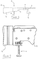
- most modern rifles 1 are of a modular construction and typically comprise a barrel 3, a firing mechanism 5 and a butt 7 bolted, or otherwise secured, to the firing mechanism 5.
- a pair of legs 9 forming a bipod are fixed to a fore-end 4 of the rifle 1, the legs being capable of supporting the front portion of the rifle.
- Figure 2 is an enlarged view of a section of the rifle of Figure 1 showing the portion of the rifle 1 where the rifle body joins with the butt 7.
- a support mechanism 11 is provided that may be adjusted by the user of the rifle for the support thereof.
- the support mechanism 11 is preferably positioned as close as possible to the butt 7 and as far away as possible from the bipod support 9 (if provided) or from the muzzle of the barrel 3.
- the support mechanism 11 of this embodiment comprises a retractable third leg that advantageously has both coarse and fine adjustment combined in the one mechanism.
- the mechanism of this embodiment provides for a more versatile support when compared to other previously proposed guns as it has a greater range of extension, and yet is advantageously still retractable inside the gun.
- the support mechanism 11 comprises an externally threaded cylinder 13 that is screwably engaged with a threaded aperture formed in the rifle body.
- the cylinder 13 is formed with a collet wheel 17 at one end, and the collet wheel 17 has a second cylinder 19 of larger diameter than the first cylinder 13 extending therefrom.
- An actuating member 21 is provided, and the member 21 is formed with a shoulder 25 that extends, when the device is assembled, into the second cylinder 19.
- the shoulder 25 of the actuating member 21 is retained within the second cylinder 19 by a spring so that the actuating member 21 normally abuts the second cylinder 19.
- a support leg 27 is inserted through the actuating member 21, the second cylinder 29 and the first cylinder 13 and is retained within the first cylinder 13 by a spring 31 that is attached at one end to the support leg 27 and at the other end to a pin inserted through the end of the first cylinder 13 furthest from the collet wheel 17.
- the support leg 27 is formed with a series of spaced grooves 33 and with a foot 35 at one end.
- the support mechanism 11 includes one or more ball bearings 37 that are trappable in grooves of the leg 27.
- the ball bearings 37 are held in the groove by the shoulder 25 of the actuating member 21 and act to resist movement of the leg 27.
- the actuating member 21 is pulled away from the collet wheel 17 against the action of the spring, the ball bearings 37 are free to move into a space formed between the leg 27 and the second cylinder 19 as a result of the removal of the shoulder 25.
- the ball bearings move into this space, they are free to move out of the groove and thus the leg may be extended or retracted as desired.
- Releasing the actuating member 21 causes the ball bearings to be driven from the space into the next available groove whereupon the leg will once more become locked.
- the tension of the spring between the actuating member 21 and the second cylinder 19 is chosen to be sufficient to ensure that the inner leg is trapped and held firmly by the action of the ball bearings in the grooves.
- the provision of the spring 31 between the leg 27 and the retaining pin advantageously provides for a very swift retraction of the support mechanism simply by pulling the actuating member 21 away from the collet wheel 17 against the action of the spring provided therebetween.
- the length of the leg 27 extending from the collet wheel 17 may easily be adjusted simply by pulling the actuating member 21 and the leg 27.
- the spaced grooves provide a number of predetermined leg extensions that may be selected at will by the operator of the gun, and it is these predetermined leg extensions that provide the aforementioned coarse leg length adjustment.
- the aforementioned fine leg length adjustment is provided simply by rotating the collet wheel 17 to unscrew the first cylinder 13 from the threaded aperture in the rifle body. Rotating the collet wheel 17 in one direction will drive the first cylinder 13, actuating member 21 and leg 27 away from the rifle body; and rotating the collet wheel 17 in the opposite direction will draw the first cylinder 13, actuating member 21 and leg 27 towards and into the rifle body.
- the arrangement described herein not only provides for coarse leg length adjustment, but also provides for fine leg length adjustment.
- the support mechanism is advantageously fully disassemblable for cleaning or maintenance as the support leg can be removed from the first cylinder 13 simply by removing the pin securing the spring 31 to the cylinder 13, and the first cylinder 13 can be wholly removed from the gun simply by rotating the collet wheel 17 to unscrew the first cylinder 13 from the gun.
- the support mechanism is also advantageously substantially retractable within the rifle body.
- the first cylinder could be screwably received within a further cylinder that is itself screwably engaged with the threaded aperture of the gun - thereby providing one leg and two screwably extendable cylinders to yet further increase the adjustability of the support.
- the support mechanism could simply comprise a telescopic arrangement with modules of the telescopic support being screwably or otherwise engageable with one another, the supporting leg either being one of said telescopic modules or being received in one of said modules in a manner similar to that substantially as described herein for the supporting leg 27.
- the supporting leg mechanism described herein could be used wholly or partly in other gun support systems. It could also be used independently to help support and aim a rifle. It could even be used as a handle by the operator for steadying and aiming the rifle.
- the support could be employed at the front of the gun as part of a bipod arrangement or as a sole support. It is also conceivable that the first cylinder could be permanently mounted in or formed as part of the firearm, with only the leg and/or intervening cylinder(s) being extendable therefrom.
Landscapes
- Engineering & Computer Science (AREA)
- General Engineering & Computer Science (AREA)
- Aiming, Guidance, Guns With A Light Source, Armor, Camouflage, And Targets (AREA)
- Telescopes (AREA)
- Emergency Lowering Means (AREA)
Applications Claiming Priority (2)
| Application Number | Priority Date | Filing Date | Title |
|---|---|---|---|
| GB9902186A GB2346202A (en) | 1999-02-01 | 1999-02-01 | Telescopic support for firearm |
| GB9902186 | 1999-02-01 |
Publications (2)
| Publication Number | Publication Date |
|---|---|
| EP1026471A2 true EP1026471A2 (fr) | 2000-08-09 |
| EP1026471A3 EP1026471A3 (fr) | 2001-04-18 |
Family
ID=10846886
Family Applications (1)
| Application Number | Title | Priority Date | Filing Date |
|---|---|---|---|
| EP00300664A Withdrawn EP1026471A3 (fr) | 1999-02-01 | 2000-01-28 | Support pour armes à feu |
Country Status (2)
| Country | Link |
|---|---|
| EP (1) | EP1026471A3 (fr) |
| GB (1) | GB2346202A (fr) |
Cited By (1)
| Publication number | Priority date | Publication date | Assignee | Title |
|---|---|---|---|---|
| AT14149U1 (de) * | 2013-03-08 | 2015-05-15 | Andreas Jakele | Schaftkappe mit Hecksporn |
Families Citing this family (9)
| Publication number | Priority date | Publication date | Assignee | Title |
|---|---|---|---|---|
| RU2227884C1 (ru) * | 2002-09-11 | 2004-04-27 | Открытое акционерное общество "Завод им. В.А. Дегтярёва" | Тумбовая оружейная установка |
| RU2253080C1 (ru) * | 2004-01-19 | 2005-05-27 | Глухов Александр Владимирович | Приспособление к ручному огнестрельному оружию |
| RU2244239C1 (ru) * | 2004-02-16 | 2005-01-10 | Открытое акционерное общество "ГАЗ" | Вращающаяся оружейная установка транспортного средства |
| RU2275574C2 (ru) * | 2004-07-27 | 2006-04-27 | Государственное унитарное предприятие "Конструкторское бюро приборостроения" | Боевое отделение |
| US7610711B2 (en) | 2005-07-18 | 2009-11-03 | TDI Arms, Ltd. | Telescoping leg |
| WO2011060481A1 (fr) * | 2009-11-18 | 2011-05-26 | Gavin William Lewis | Support de fusil |
| CN106440931A (zh) * | 2016-04-15 | 2017-02-22 | 陈小鸣 | 一种管后端压缩射出的两脚架 |
| CN108036675A (zh) * | 2017-11-25 | 2018-05-15 | 四川华庆机械有限责任公司 | 一种多功能狙击枪枪托 |
| US10139183B1 (en) * | 2018-01-26 | 2018-11-27 | Cheh-Kang Liu | Bipod |
Family Cites Families (11)
| Publication number | Priority date | Publication date | Assignee | Title |
|---|---|---|---|---|
| GB191515208A (en) * | 1915-10-28 | 1916-10-26 | Birmingham Small Arms Co Ltd | Improvements in and relating to Mountings for Machine Guns and the like. |
| US1367354A (en) * | 1919-11-19 | 1921-02-01 | Alvin M Craig | Shock-diffuser for firearms |
| US2844905A (en) * | 1952-11-21 | 1958-07-29 | Musser C Walton | Telescopic unipod |
| US4393614A (en) * | 1980-06-09 | 1983-07-19 | Pickett Fred E | Gun rest |
| EP0127194A1 (fr) * | 1980-12-11 | 1984-12-05 | Chartered Industries Of Singapore Private Limited | Amortisseur de gâchette pour arme à feu à action de gaz et arme à feu comportant un tel amortisseur |
| US4910904A (en) * | 1989-03-27 | 1990-03-27 | Browning | Recoil reducer for firearms |
| US5081782A (en) * | 1990-08-20 | 1992-01-21 | Wright Lloyd A | Gun stand |
| US5345706A (en) * | 1993-06-25 | 1994-09-13 | Huntech, Inc. | Firearm support |
| US5438786A (en) * | 1993-12-10 | 1995-08-08 | Hilderbrand; Darrell P. | Pistol rest |
| US5711103A (en) * | 1995-10-13 | 1998-01-27 | Keng; Da | Bipod mounting device |
| GB2332038A (en) * | 1997-12-05 | 1999-06-09 | Thompson & Campbell Ltd | Firearm and accessories |
-
1999
- 1999-02-01 GB GB9902186A patent/GB2346202A/en not_active Withdrawn
-
2000
- 2000-01-28 EP EP00300664A patent/EP1026471A3/fr not_active Withdrawn
Non-Patent Citations (1)
| Title |
|---|
| None |
Cited By (1)
| Publication number | Priority date | Publication date | Assignee | Title |
|---|---|---|---|---|
| AT14149U1 (de) * | 2013-03-08 | 2015-05-15 | Andreas Jakele | Schaftkappe mit Hecksporn |
Also Published As
| Publication number | Publication date |
|---|---|
| GB9902186D0 (en) | 1999-03-24 |
| GB2346202A (en) | 2000-08-02 |
| EP1026471A3 (fr) | 2001-04-18 |
Similar Documents
| Publication | Publication Date | Title |
|---|---|---|
| US10871344B2 (en) | Firearm with self-deploying stock | |
| US9121665B2 (en) | Gun with internally stored bipod and monopod | |
| US4393614A (en) | Gun rest | |
| CA2495379C (fr) | Systeme de recul destine a la boite de culasse d'une arme a feu | |
| US9574839B2 (en) | Foldable and adjustable bipod rest | |
| US4345398A (en) | Gun rest | |
| US20210108876A1 (en) | Bipod firearm support | |
| EP3507563B1 (fr) | Extension pour un support d'arme à feu | |
| US9470468B2 (en) | Handguard with integrated pod and firearm | |
| US8448369B2 (en) | Bipod device for use with Picatinny rail | |
| US11391533B2 (en) | Rifle bipod | |
| US8276306B2 (en) | Rear firearm grip support rod and aiming method | |
| US20200340772A1 (en) | Adjustable Firearm Support | |
| US7434773B1 (en) | Adjustable support for archery bows and the like | |
| EP1026471A2 (fr) | Support pour armes à feu | |
| US20140361143A1 (en) | Archery Bow Support Device | |
| US20170089659A1 (en) | Height adjustable rear grip aiming support for a firearm | |
| US20190277593A1 (en) | Support | |
| US11428492B1 (en) | Firearm support base and related method of use | |
| US11530896B2 (en) | Firearm with integrated levelers | |
| EP4579170A1 (fr) | Extension motorisée pour support de fusil bipode |
Legal Events
| Date | Code | Title | Description |
|---|---|---|---|
| PUAI | Public reference made under article 153(3) epc to a published international application that has entered the european phase |
Free format text: ORIGINAL CODE: 0009012 |
|
| AK | Designated contracting states |
Kind code of ref document: A2 Designated state(s): AT BE CH CY DE DK ES FI FR GB GR IE IT LI LU MC NL PT SE |
|
| AX | Request for extension of the european patent |
Free format text: AL;LT;LV;MK;RO;SI |
|
| PUAL | Search report despatched |
Free format text: ORIGINAL CODE: 0009013 |
|
| AK | Designated contracting states |
Kind code of ref document: A3 Designated state(s): AT BE CH CY DE DK ES FI FR GB GR IE IT LI LU MC NL PT SE |
|
| AX | Request for extension of the european patent |
Free format text: AL;LT;LV;MK;RO;SI |
|
| RIC1 | Information provided on ipc code assigned before grant |
Free format text: 7F 41A 23/06 A, 7F 41A 23/10 B |
|
| AKX | Designation fees paid | ||
| REG | Reference to a national code |
Ref country code: DE Ref legal event code: 8566 |
|
| STAA | Information on the status of an ep patent application or granted ep patent |
Free format text: STATUS: THE APPLICATION IS DEEMED TO BE WITHDRAWN |
|
| 18D | Application deemed to be withdrawn |
Effective date: 20011019 |