EP4579185A1 - Verfahren zur bestimmung und visualisierung einer genauigkeitskarte - Google Patents
Verfahren zur bestimmung und visualisierung einer genauigkeitskarte Download PDFInfo
- Publication number
- EP4579185A1 EP4579185A1 EP24188392.5A EP24188392A EP4579185A1 EP 4579185 A1 EP4579185 A1 EP 4579185A1 EP 24188392 A EP24188392 A EP 24188392A EP 4579185 A1 EP4579185 A1 EP 4579185A1
- Authority
- EP
- European Patent Office
- Prior art keywords
- ori
- surveying instrument
- accuracy
- pose
- new
- Prior art date
- Legal status (The legal status is an assumption and is not a legal conclusion. Google has not performed a legal analysis and makes no representation as to the accuracy of the status listed.)
- Pending
Links
Images



Classifications
-
- G—PHYSICS
- G01—MEASURING; TESTING
- G01C—MEASURING DISTANCES, LEVELS OR BEARINGS; SURVEYING; NAVIGATION; GYROSCOPIC INSTRUMENTS; PHOTOGRAMMETRY OR VIDEOGRAMMETRY
- G01C15/00—Surveying instruments or accessories not provided for in groups G01C1/00 - G01C13/00
- G01C15/002—Active optical surveying means
Definitions
- a computer-implemented method for determining for a working area at a worksite in which a surveying instrument is deployed at a station, an accuracy map, which shows for the working area at least one accuracy that can be achieved during operating the surveying instrument, the method being performed by a computer system and comprising the steps:
- the worksite defines the three-dimensional environment, in which the surveying instrument is deployed at a station, and the working area is that part of the worksite, in which the surveying instrument is operating, and the operator is interested in during operating the surveying instrument, wherein the working area is typically a two-dimensional area.
- the accuracies that can be achieved during operating the surveying instrument are computed based on the pose vector, the variances and covariances of the pose elements, on measuring accuracies of the surveying instrument, and on representative coordinates of the surface elements; representative coordinates of the surface elements can be a center point or any other point of the surface elements.
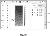
- the accuracy map which shows the accuracies that can be achieved during operating the surveying instrument, is computed based on the accuracies computed for the surface elements. Finally, a display is instructed to visualize a graphical representation of the accuracy map on the display.
- the working area is computed by the computer system based on a set of control points.
- the definition of the working area is necessary to define that area of the worksite the operator is interested in during operating the surveying instrument.
- the working area is computed by the computer system based on a polygon or a polyline or a set of corner points defined by an operator.
- the definition of the working area is necessary to define that area of the worksite the operator is interested in during operating the surveying instrument. If the operator defines the working area, the computation of the accuracy map can be restricted to that area of the worksite the operator is really interested in.
- the accuracy map is stored in the computer system and/or stored to a memory connected to the computer system and the accuracy map is provided for use in operating the surveying instrument.
- the operator is supported in the interpretation of the data, he can easily check via the graphical representation of the accuracy map, if he can achieve the required accuracy.
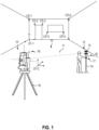
- FIG. 1 shows an operator using a surveying instrument 10 deployed at a worksite 11.
- the worksite 11 may be a construction site, inside or outside, or a surveying site, amongst others.
- a target 12 that is remote from the surveying instrument 10 may be deployed at the worksite 11.
- the target 12 may include a reflector 13, such as a prism and/or a cat-eye, that is mounted on top of a pole 14.
- the surveying instrument 10 is formed as a total station and comprises a measuring unit 15 that is mounted on a mounting support structure in the form of a tripod 16.
- the surveying instrument 10 also comprises a removable control panel in the form of a remote controller 17 that can be used for remote control of the measuring unit 15 via a wireless connection 18.
- the total station 10 Before the operator can use the total station 10 for layouting, measuring and/or other tasks, the total station must be stationed via a stationing process to the worksite 11.
- stationing processes are known, such as free-stationing process, model-based stationing process, automatic stationing process, or any other stationing process.
- the total station 10 To determine the pose (position and orientation) of the total station 10 in the coordinate frame of the worksite 11, the total station 10 sights a number of the control points and takes measurement samples of distance and angle data in its coordinate frame.
- the coordinate frame of the worksite 11 is called “first coordinate frame” CF-1 and the coordinate frame of the total station 10 is called “second coordinate frame” CF-2.
- the coordinates in the first coordinate frame CF-1 are called “first coordinates” and the coordinates in the second coordinate frame CF-2 are called “second coordinates".
- the pose of the total station can be calculated from the first coordinates of the control points in the first coordinate frame CF-1 and from the second coordinates of the control points in the second coordinate frame CF-2.
- the position accuracy of the pose can increase.
- FIGS. 2A , B show an exemplary version of the measuring unit 15 used in the surveying instrument 10 of FIG. 1 in a perspective view ( FIG. 2A ) and a block diagram of the main components of the measuring unit 15 as illustrated in FIG. 2A ( FIG. 2B ).
- the surveying instrument 10 is designed as robotic total station and the measuring unit 15 comprises a base 21, a support 22, and a measuring head 23 .
- the measuring head 23 is enclosed by a housing 24, which includes an exit window 25 .
- a distance measuring device that can emit a distance measuring beam and a tracking device that can emit a radiation are arranged. The distance measuring beam and the radiation are emitted through the exit window 25 to leave the housing 24.
- the support 22 is U-formed and includes a bottom portion 27, a first side portion 28, and a second side portion 29 .
- the support 22 can rotate completely around its circumference at a full 360° angle with respect to the base 21 about a first axis of rotation 31 .
- the measuring head 23 is pivotably mounted to the support 22 about a second axis of rotation 32 and is arranged between the first side portion 28 and the second side portion 29 of the support.
- the first axis of rotation 31 is aligned parallel to a local direction of gravitation 33
- the second axis of rotation 32 is aligned perpendicular to the local direction of gravitation 33.
- An azimuth motor device and a first angle encoder may be located in the bottom portion 27 of the support 22 and allow to rotate the measuring unit 15 about the first axis of rotation 31 and to determine the direction of the distance measuring beam in a first plane perpendicular to the first axis of rotation 31.
- An elevation motor device and a second angle encoder may be located in the first side portion 28 of the support 22 and allow the measuring head 23 to pivot about the second axis of rotation 32 and to determine the direction of the distance measuring beam in a second plane perpendicular to the second axis of rotation 32.
- a self-leveling device which may be arranged in the bottom portion 27 of the support 22, can be included.
- FIG. 2B shows a block diagram of the main components of the measuring unit 15 of the surveying instrument 10.
- the measuring unit 15 includes a first electronic device 41 , a distance measuring device 42, a first angle encoder 43, an azimuth motor device 44 , a second angle encoder 45, and an elevation motor device 46.
- the measuring unit 15 can additionally include one or more cameras, such as a tracking camera configured to track a reflector target, or an aiming camera configured to let the user aim to a point of interest.
- the first electronic device 41 comprises a first processing circuit ( ⁇ P) 50, a first memory circuit 51 that may include associated random-access memory (RAM) and read only memory (ROM), a first communications circuit 52, and a first input/output (I/O) interface circuit 53.
- the first processing circuit 50 also called device control unit, may communicate with the first memory circuit 51 and first communications circuit 52 and is configured to control the laser instrument 12.
- the first communications circuit 52 includes a first transmitter circuit 54 and a first receiver circuit 55 and is configured to be connected to a communications circuit of the remote controller via the communication link.
- the first input/output interface circuit 53 is an interface between the first processing circuit 50 and the various types of motor driver circuits and sensor circuits of the measuring unit 15.
- the second electronic device 91 comprises a second processing circuit ( ⁇ P) 94, a second memory circuit 95 that may include associated random-access memory (RAM), read only memory (ROM), and some type of bulk memory (BULK), a second communications circuit 96 , and a second input/output (I/O) interface circuit 97.
- the second processing circuit 94 may communicate with the second memory circuit 95 and second communications circuit 96 and is configured to control the remote controller 17.
- the second communications circuit 96 includes a second transmitter circuit 98 and a second receiver circuit 99 and is configured to be connected to the first communications circuit 52 of the measuring unit 15 via the wireless communication 18.
- the second input/output interface circuit 97 is an interface between the second processing circuit 94 and the various driver circuits of the remote controller 17.
- the stored program codes may include a program code for performing a method for determining for a working area at a worksite, in which a surveying instrument is deployed, an accuracy map, which shows for the working area at least one accuracy that can be achieved during operating the surveying instrument.
- the computer system is integrated into the second processing circuit 94 of the second electronic device 91 of the remote controller 17.
- the computer system may be integrated into the first processing circuit 50, or into the first and second processing circuits 50, 94, or in any other type of suitable processing circuit.
- the display device 92 includes a display 101 and a display driver circuit 102.
- the display driver circuit will be in communication with the second I/O interface circuit 97 and provides the correct interface and data signals for the display 101. If the remote controller 17 is a laptop computer, for example, then this would be the standard display seen in most laptop computers. Or, if the remote controller 17 is a tablet computer or a smart phone, in which case the display device is a much smaller physical device, the display device 101 could be a touch screen display.
- the user-operated input device 93 includes a keypad 103 and a keypad driver circuit 104.
- the keypad driver circuit will be in communication with the second I/O interface circuit 97 and controls the signals that interface to the keypad 103. If the display device 101 is a touch screen display, then there may not be a separate keypad on the remote controller 17, because most of the command or data to input functions will be available by touching the display itself and the keypad is integrated in the touch screen display. There may be some type of power on/off button, but that would not necessarily be considered a true keypad and typically would not be used for entering data.
- the worksite defines the three-dimensional environment, in which the surveying instrument 10 is deployed at a station, and the working area is that part of the worksite, in which the surveying instrument 10 is operating, wherein the working area is typically a two-dimensional area.
- the term "station” is used to clarify that the surveying instrument 10 is arranged at a fixed position and not moved in the worksite. At its station, the position of the surveying instrument 10 is fixed, but the head of the surveying instrument 10 can rotate about its axes of rotation 31, 32.
- the method for determining an accuracy map for a working area comprises the following steps:
- steps of the method are illustrated in a particular order, in some embodiments, one or more steps may be executed in a different order than illustrated in FIG. 4 .
- steps S10 and S20 can be executed in a different order, but the steps S10 and S20 must be executed before step S30 and the steps S30 to S50 must be executed in that order shown in FIG. 4 .
- step S10 the grid pattern of surface elements is created for the working area.
- the resolution of the grid pattern and the form the surface elements will adapted to the working area.
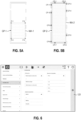
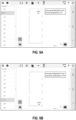
- FIGS. 5A , B show a worksite that is an inside construction worksite limited by walls.
- the working area is that area of the worksite, the operator is interested in and in which the surveying instrument 10 is planned to be operated.
- FIG. 5A shows a first working area WA-1 that is defined by an operator.
- the operator can define corner points, here P-1 , P-2 , P-3 , and P-4 , and the computer system 94 creates a polygon based on the corner points, or the operator defines the polygon.
- a 11 x 10 grid pattern GP-1 of rectangular surface elements is created.
- model-based stationing processes for determining a pose for a surveying instrument without using a set of control points having known coordinates in the first coordinate frame of the worksite are disclosed.
Landscapes
- Physics & Mathematics (AREA)
- Engineering & Computer Science (AREA)
- General Physics & Mathematics (AREA)
- Radar, Positioning & Navigation (AREA)
- Remote Sensing (AREA)
- Length Measuring Devices With Unspecified Measuring Means (AREA)
Priority Applications (1)
| Application Number | Priority Date | Filing Date | Title |
|---|---|---|---|
| PCT/EP2024/087105 WO2025140907A1 (en) | 2023-12-31 | 2024-12-18 | Method for determining and visualizing an accuracy map |
Applications Claiming Priority (1)
| Application Number | Priority Date | Filing Date | Title |
|---|---|---|---|
| EP23220886.8A EP4579182A1 (de) | 2023-12-31 | 2023-12-31 | Verfahren zur bestimmung und visualisierung einer genauigkeitskarte |
Publications (1)
| Publication Number | Publication Date |
|---|---|
| EP4579185A1 true EP4579185A1 (de) | 2025-07-02 |
Family
ID=89473404
Family Applications (2)
| Application Number | Title | Priority Date | Filing Date |
|---|---|---|---|
| EP23220886.8A Pending EP4579182A1 (de) | 2023-12-31 | 2023-12-31 | Verfahren zur bestimmung und visualisierung einer genauigkeitskarte |
| EP24188392.5A Pending EP4579185A1 (de) | 2023-12-31 | 2024-07-12 | Verfahren zur bestimmung und visualisierung einer genauigkeitskarte |
Family Applications Before (1)
| Application Number | Title | Priority Date | Filing Date |
|---|---|---|---|
| EP23220886.8A Pending EP4579182A1 (de) | 2023-12-31 | 2023-12-31 | Verfahren zur bestimmung und visualisierung einer genauigkeitskarte |
Country Status (1)
| Country | Link |
|---|---|
| EP (2) | EP4579182A1 (de) |
Families Citing this family (1)
| Publication number | Priority date | Publication date | Assignee | Title |
|---|---|---|---|---|
| EP4679032A1 (de) * | 2024-07-12 | 2026-01-14 | Hilti Aktiengesellschaft | Verfahren zur bestimmung einer genauigkeit für einen punkt von interesse |
Citations (5)
| Publication number | Priority date | Publication date | Assignee | Title |
|---|---|---|---|---|
| US20100309311A1 (en) * | 2008-02-12 | 2010-12-09 | Trimble Ab | Localization of a surveying instrument in relation to a ground mark |
| US20210055102A1 (en) * | 2019-08-22 | 2021-02-25 | Leica Geosystems Ag | Surveying system with image-based measuring |
| CN112964237A (zh) * | 2021-02-10 | 2021-06-15 | 北京测绘学会 | 针对施工工程的测量控制系统、方法、装置、计算机设备 |
| WO2024141425A1 (en) | 2023-01-01 | 2024-07-04 | Hilti Aktiengesellschaft | Method and system for determining a pose for a laser instrument |
| WO2024141424A1 (en) | 2022-12-31 | 2024-07-04 | Hilti Aktiengesellschaft | Method and system for determining a pose for a laser instrument |
-
2023
- 2023-12-31 EP EP23220886.8A patent/EP4579182A1/de active Pending
-
2024
- 2024-07-12 EP EP24188392.5A patent/EP4579185A1/de active Pending
Patent Citations (5)
| Publication number | Priority date | Publication date | Assignee | Title |
|---|---|---|---|---|
| US20100309311A1 (en) * | 2008-02-12 | 2010-12-09 | Trimble Ab | Localization of a surveying instrument in relation to a ground mark |
| US20210055102A1 (en) * | 2019-08-22 | 2021-02-25 | Leica Geosystems Ag | Surveying system with image-based measuring |
| CN112964237A (zh) * | 2021-02-10 | 2021-06-15 | 北京测绘学会 | 针对施工工程的测量控制系统、方法、装置、计算机设备 |
| WO2024141424A1 (en) | 2022-12-31 | 2024-07-04 | Hilti Aktiengesellschaft | Method and system for determining a pose for a laser instrument |
| WO2024141425A1 (en) | 2023-01-01 | 2024-07-04 | Hilti Aktiengesellschaft | Method and system for determining a pose for a laser instrument |
Non-Patent Citations (1)
| Title |
|---|
| UMEYAMASHINJI: "Least-squares estimation of transformation parameters between two point patterns", IEEE TRANSACTIONS ON PATTERN ANALYSIS & MACHINE INTELLIGENCE, vol. 13, no. 04, 1991, pages 376 - 380, XP002317333, DOI: 10.1109/34.88573 |
Also Published As
| Publication number | Publication date |
|---|---|
| EP4579182A1 (de) | 2025-07-02 |
Similar Documents
| Publication | Publication Date | Title |
|---|---|---|
| US10586349B2 (en) | Excavator bucket positioning via mobile device | |
| US12183018B2 (en) | Correction of current scan data using pre-existing data | |
| US11461526B2 (en) | System and method of automatic re-localization and automatic alignment of existing non-digital floor plans | |
| US9584768B2 (en) | Information processing apparatus, information processing method and computer-readable storage medium | |
| US10896517B2 (en) | System and method of scanning an environment | |
| EP4242585A2 (de) | Vermessungsassistenzsystem, informationsanzeigeendgerät, vermessungsassistenzverfahren und vermessungsassistenzprogramm | |
| EP3479143B1 (de) | Tragbares strahlungsmessgerät und verfahren | |
| EP4579185A1 (de) | Verfahren zur bestimmung und visualisierung einer genauigkeitskarte | |
| EP3745159A1 (de) | System und verfahren zur automatischen erzeugung von abtaststellen zur durchführung einer abtastung einer umgebung | |
| US20190251741A1 (en) | System and method of on-site documentation enhancement through augmented reality | |
| EP3527938B1 (de) | Distanzmesssystem mit layout-erzeugungsfunktionalität | |
| WO2021174037A1 (en) | Laser alignment device | |
| JP6812114B2 (ja) | 測量位置表示装置及び測量位置表示プログラム | |
| EP4679032A1 (de) | Verfahren zur bestimmung einer genauigkeit für einen punkt von interesse | |
| EP4579181A1 (de) | Verfahren zur optimierung und visualisierung eines layoutbereichs | |
| EP4579180A1 (de) | Verfahren zur bestimmung und visualisierung eines layoutbereichs | |
| WO2025140907A1 (en) | Method for determining and visualizing an accuracy map | |
| US20210404792A1 (en) | User interface for three-dimensional measurement device | |
| US20130021618A1 (en) | Apparatus and method to indicate a specified position using two or more intersecting lasers lines | |
| US12163786B2 (en) | Construction verification system, method and computer program product | |
| EP4696981A1 (de) | Motorisierter layoutzeiger mit entfernungsmesseinheit und verfahren zur anzeige eines layoutpunktes an einer baustelle | |
| EP4696978A1 (de) | Vorrichtung und verfahren zur anzeige eines layoutpunktes an einer baustelle unter verwendung einer total station | |
| EP4696980A1 (de) | Motorisierter layoutzeiger und verfahren zur anzeige eines layoutpunktes an einer baustelle | |
| US11486701B2 (en) | System and method for performing a real-time wall detection | |
| US20210142060A1 (en) | System and method for monitoring and servicing an object within a location |
Legal Events
| Date | Code | Title | Description |
|---|---|---|---|
| PUAI | Public reference made under article 153(3) epc to a published international application that has entered the european phase |
Free format text: ORIGINAL CODE: 0009012 |
|
| STAA | Information on the status of an ep patent application or granted ep patent |
Free format text: STATUS: THE APPLICATION HAS BEEN PUBLISHED |
|
| AK | Designated contracting states |
Kind code of ref document: A1 Designated state(s): AL AT BE BG CH CY CZ DE DK EE ES FI FR GB GR HR HU IE IS IT LI LT LU LV MC ME MK MT NL NO PL PT RO RS SE SI SK SM TR |