EP4579241A1 - Dispositif d'analyse automatique et procédé de commande associé - Google Patents
Dispositif d'analyse automatique et procédé de commande associé Download PDFInfo
- Publication number
- EP4579241A1 EP4579241A1 EP23855847.2A EP23855847A EP4579241A1 EP 4579241 A1 EP4579241 A1 EP 4579241A1 EP 23855847 A EP23855847 A EP 23855847A EP 4579241 A1 EP4579241 A1 EP 4579241A1
- Authority
- EP
- European Patent Office
- Prior art keywords
- remaining time
- analysis
- time
- analysis module
- display unit
- Prior art date
- Legal status (The legal status is an assumption and is not a legal conclusion. Google has not performed a legal analysis and makes no representation as to the accuracy of the status listed.)
- Pending
Links
Images






Classifications
-
- G—PHYSICS
- G01—MEASURING; TESTING
- G01N—INVESTIGATING OR ANALYSING MATERIALS BY DETERMINING THEIR CHEMICAL OR PHYSICAL PROPERTIES
- G01N35/00—Automatic analysis not limited to methods or materials provided for in any single one of groups G01N1/00 - G01N33/00; Handling materials therefor
- G01N35/00584—Control arrangements for automatic analysers
- G01N35/0092—Scheduling
-
- G—PHYSICS
- G01—MEASURING; TESTING
- G01N—INVESTIGATING OR ANALYSING MATERIALS BY DETERMINING THEIR CHEMICAL OR PHYSICAL PROPERTIES
- G01N35/00—Automatic analysis not limited to methods or materials provided for in any single one of groups G01N1/00 - G01N33/00; Handling materials therefor
- G01N35/00584—Control arrangements for automatic analysers
- G01N35/00722—Communications; Identification
-
- G—PHYSICS
- G01—MEASURING; TESTING
- G01N—INVESTIGATING OR ANALYSING MATERIALS BY DETERMINING THEIR CHEMICAL OR PHYSICAL PROPERTIES
- G01N35/00—Automatic analysis not limited to methods or materials provided for in any single one of groups G01N1/00 - G01N33/00; Handling materials therefor
- G01N35/10—Devices for transferring samples or any liquids to, in, or from, the analysis apparatus, e.g. suction devices, injection devices
- G01N35/1002—Reagent dispensers
-
- G—PHYSICS
- G01—MEASURING; TESTING
- G01N—INVESTIGATING OR ANALYSING MATERIALS BY DETERMINING THEIR CHEMICAL OR PHYSICAL PROPERTIES
- G01N35/00—Automatic analysis not limited to methods or materials provided for in any single one of groups G01N1/00 - G01N33/00; Handling materials therefor
- G01N35/00584—Control arrangements for automatic analysers
- G01N35/00594—Quality control, including calibration or testing of components of the analyser
- G01N35/00613—Quality control
- G01N35/00663—Quality control of consumables
- G01N2035/00673—Quality control of consumables of reagents
-
- G—PHYSICS
- G01—MEASURING; TESTING
- G01N—INVESTIGATING OR ANALYSING MATERIALS BY DETERMINING THEIR CHEMICAL OR PHYSICAL PROPERTIES
- G01N35/00—Automatic analysis not limited to methods or materials provided for in any single one of groups G01N1/00 - G01N33/00; Handling materials therefor
- G01N35/00584—Control arrangements for automatic analysers
- G01N35/00722—Communications; Identification
- G01N2035/00891—Displaying information to the operator
- G01N2035/0091—GUI [graphical user interfaces]
-
- G—PHYSICS
- G01—MEASURING; TESTING
- G01N—INVESTIGATING OR ANALYSING MATERIALS BY DETERMINING THEIR CHEMICAL OR PHYSICAL PROPERTIES
- G01N35/00—Automatic analysis not limited to methods or materials provided for in any single one of groups G01N1/00 - G01N33/00; Handling materials therefor
- G01N35/02—Automatic analysis not limited to methods or materials provided for in any single one of groups G01N1/00 - G01N33/00; Handling materials therefor using a plurality of sample containers moved by a conveyor system past one or more treatment or analysis stations
- G01N35/04—Details of the conveyor system
- G01N2035/0401—Sample carriers, cuvettes or reaction vessels
- G01N2035/0437—Cleaning cuvettes or reaction vessels
Definitions
- the present invention relates to an automatic analyzer for analyzing a specimen such as blood, urine, or cerebrospinal fluid, and in particular to a function of displaying a state of the automatic analyzer.
- an automatic analyzer since a plurality of specimens are automatically analyzed according to a preset analysis order or analysis conditions, an operator can leave the automatic analyzer and perform other work during automatic analysis.
- PTL 1 discloses an automatic analyzer that accurately estimates and presents an analysis end time.
- a pre-analysis preparation time is stored in association with a transition state of an analysis condition, for example, a set temperature of a column oven, and an analysis end time is estimated based on the pre-analysis preparation time read out according to the transition state of the analysis condition and an analysis time. If the set temperature is not changed, the pre-analysis preparation time is short since it is not necessary to raise or lower a temperature of the column oven. However, if the set temperature is changed, the pre-analysis preparation time is long since a time is required for raising and lowering the temperature. That is, the analysis end time is accurately estimated by using the pre-analysis preparation time read out according to the transition state of the analysis condition.
- An object of the invention is to provide an automatic analyzer capable of more accurately obtaining a time required for a pre-operation from reception of an analysis instruction to start of analysis.
- an automatic analyzer capable of more accurately obtaining a time required for a pre-operation from reception of an analysis instruction to start of analysis.
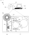
- the transport module 101 is a module that transports a specimen rack 104 on which a specimen container containing a specimen is mounted to the analysis module 111, and includes a rack supply tray 102, a rack buffer 103, a transport line 105, and a rack storage tray 106.
- the rack storage tray 106 accumulates the specimen rack 104 carried out from the rack buffer 103.
- the analysis module control unit 119 controls operations of various mechanisms in the analysis module 111 and transmits measurement results from the analysis unit to the operation module 121, and is implemented by, for example, a micro processor unit (MPU).
- MPU micro processor unit
- the operation module 121 is a module that controls the transport module 101 and the analysis module 111 according to an instruction from an operator, and includes an input unit 122, a display unit 123, a storage unit 124, and a control unit 125.
- the input unit 122 is a device to which an instruction from an operator is input, and is implemented by, for example, a keyboard, a mouse, and a touch panel.
- the display unit 123 is a device that displays analysis conditions set via the input unit 122, a state of the analysis module 111, a measurement result from the analysis unit, and the like, and is implemented by, for example, a liquid crystal monitor or a touch panel.
- the storage unit 124 is a device that stores a program and data used for controlling the transport module 101 and the analysis module 111, measurement results from the analysis unit, and the like, and is implemented by, for example, a hard disk drive (HDD) and a solid state drive (SSD) .
- HDD hard disk drive
- SSD solid state drive
- the control unit 125 is a device that controls each unit, and is implemented by, for example, a central processing unit (CPU). Under the control of the control unit 125, the analysis module 111 transitions from a standby state to a pre-operation, an operation, and a post-operation in this order.
- CPU central processing unit
- the standby state is a state of waiting for an analysis instruction from the operator, the pre-operation is a preparation operation before the analysis, the operation is an analysis operation, and the post-operation is an operation for transitioning to the standby state after the analysis.
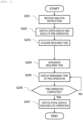
- Embodiment 1 An example of a flow of processing performed in Embodiment 1 will be described for each step with reference to FIG. 2 .
- the control unit 125 receives an analysis instruction input to the input unit 122.
- the control unit 125 switches a state display of the analysis module 111 from a standby state to a pre-operation and causes the analysis module 111 to execute the pre-operation.
- the control unit 125 or the analysis module control unit 119 acquires each required time for each item to be executed as the pre-operation.
- the required time is read out from a pre-operation table 301 shown in FIG. 3 .
- the pre-operation table 301 is a table in which a pre-operation item 302 and a required time 303 are associated with each other, and is stored in advance in the storage unit 124.
- the pre-operation item 302 includes processing such as mechanism reset, pressure sensor check, and reagent registration.
- the mechanism reset it is confirmed that various mechanisms such as the specimen dispensing line 112, the specimen dispensing probe 113, the reagent dispensing probe 116, the reagent disk 117, and the reaction disk 115 return to initial positions, and it is determined that there is an abnormality in the mechanism that does not return to the initial position. That is, the mechanism reset is one of operation confirmation of various mechanisms.
- T1 is stored as a time required for the mechanism reset. Since the mechanism reset includes collection of the specimen rack 104 in the analysis module 111, the required time is undetermined until the number of specimen racks 104 is determined.
- the pressure sensor check a pressure value of a pressure sensor in the specimen dispensing probe 113 or the reagent dispensing probe 116 is confirmed, and if the pressure value is not in a normal range, it is determined that the pressure sensor is abnormal. That is, the pressure sensor check is one of operation confirmation of various mechanisms.
- T2 is stored as a time required for the pressure sensor check.
- the control unit 125 or the analysis module control unit 119 calculates a time required to execute the pre-operation by integrating the required times acquired in S203. For example, when the required time is read out from the pre-operation table 301 shown in FIG. 3 , the time required to execute the pre-operation is T1 + T2 + T3. When there is no replacement of the reagent bottle, the time required to execute the pre-operation is T1 + T2.
- processing X, processing Y, and processing Z which are items of the post-operation, are sequentially performed.
- the display of the state display unit 402 is switched to a standby state, no remaining time is displayed in the remaining time display unit 403, and the analysis module 111 is in the standby state.
- the state of the automatic analyzer 100 and the remaining time of the post-operation are displayed on the display unit 123, so that an operator who leaves the automatic analyzer 100 can return around a time when the automatic analyzer 100 transitions to the standby state, prepare for the next analysis, or the like.
- Embodiment 1 the remaining time displayed when the required time for each item of the pre-operation is determined is described. In Embodiment 3, the remaining time displayed when a required time for each item of the pre-operation is not determined will be described.
- the configuration of the automatic analyzer 100 is the same as that of Embodiment 1, and the description thereof is omitted.
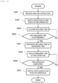
- Embodiment 3 An example of a flow of processing performed in Embodiment 3 will be described for each step with reference to FIG. 9 . The description of the same processing as in Embodiment 1 is simplified.
- control unit 125 when the control unit 125 receives an analysis instruction, the control unit 125 acquires a required time for each item while causing the analysis module 111 to execute a pre-operation.
- the control unit 125 determines whether all required times acquired in S203 are determined. That is, in the mechanism reset, the required time is undetermined until the number of specimen racks 104 in the analysis module 111 is determined, and in the reagent registration, the required time is undetermined until the number of replacement of the reagent bottles is determined. If the required time is not determined, the processing returns to S203, and if all required times are determined, the processing proceeds to S901.
- the control unit 125 calculates a time required to execute the pre-operation by integrating required times of unexecuted items.
- control unit 125 displays the remaining time of the pre-operation on the display unit 123, and causes the analysis module 111 to execute an operation when the pre-operation is completed.
- FIG. 10 shows display in the state display unit 402 and the remaining time display unit 403, and a time lapse of processing performed by the analysis module 111.
- the standby state is displayed in the state display unit 402, no remaining time is displayed in the remaining time display unit 403, and there is no processing performed by the analysis module 111.
- the display of the state display unit 402 is switched to an operation, no remaining time is displayed in the remaining time display unit 403, and the analysis module 111 starts analysis.
- the state of the automatic analyzer 100 is displayed, and after the remaining time of the pre-operation is determined, the remaining time is displayed on the display unit 123, so that an operator who leaves the automatic analyzer 100 can return around a start time of the analysis and confirm that the analysis is started without any problems.
- the remaining time of the pre-operation is calculated based on a time required for operation confirmation of various mechanisms, and thus is obtained more accurately.
- the remaining time display is not limited to the flow of the processing in FIG. 9 .
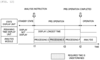
- Embodiment 3 Another example of the flow of the processing performed in Embodiment 3 will be described for each step with reference to FIG. 11 .
- the description of the same processing as in Embodiment 1 is simplified.
- control unit 125 when the control unit 125 receives an analysis instruction, the control unit 125 acquires a required time for each item while causing the analysis module 111 to execute a pre-operation.
- the control unit 125 determines whether all required times acquired in S203 are determined. If the required time is not determined, the processing proceeds to S1101, and if all required times are determined, the processing proceeds to S204.
- the control unit 125 sets the longest time for an item for which required time is not determined.
- the longest time is stored in the storage unit 124 in advance for each item.
Landscapes
- Physics & Mathematics (AREA)
- Health & Medical Sciences (AREA)
- Life Sciences & Earth Sciences (AREA)
- Chemical & Material Sciences (AREA)
- Analytical Chemistry (AREA)
- Biochemistry (AREA)
- General Health & Medical Sciences (AREA)
- General Physics & Mathematics (AREA)
- Immunology (AREA)
- Pathology (AREA)
- Automatic Analysis And Handling Materials Therefor (AREA)
Applications Claiming Priority (2)
| Application Number | Priority Date | Filing Date | Title |
|---|---|---|---|
| JP2022135055 | 2022-08-26 | ||
| PCT/JP2023/019594 WO2024042801A1 (fr) | 2022-08-26 | 2023-05-26 | Dispositif d'analyse automatique et procédé de commande associé |
Publications (1)
| Publication Number | Publication Date |
|---|---|
| EP4579241A1 true EP4579241A1 (fr) | 2025-07-02 |
Family
ID=90012926
Family Applications (1)
| Application Number | Title | Priority Date | Filing Date |
|---|---|---|---|
| EP23855847.2A Pending EP4579241A1 (fr) | 2022-08-26 | 2023-05-26 | Dispositif d'analyse automatique et procédé de commande associé |
Country Status (5)
| Country | Link |
|---|---|
| US (1) | US20260043819A1 (fr) |
| EP (1) | EP4579241A1 (fr) |
| JP (1) | JP7773656B2 (fr) |
| CN (1) | CN119630971A (fr) |
| WO (1) | WO2024042801A1 (fr) |
Family Cites Families (9)
| Publication number | Priority date | Publication date | Assignee | Title |
|---|---|---|---|---|
| JPS6025990B2 (ja) * | 1978-01-25 | 1985-06-21 | 株式会社日立製作所 | 洗濯機の稼動方法 |
| JPH0363568A (ja) * | 1989-07-31 | 1991-03-19 | Mitsui Toatsu Chem Inc | 液状樹脂自動分析におけるモニタリング方式 |
| JP4428077B2 (ja) * | 2004-02-16 | 2010-03-10 | 株式会社島津製作所 | 自動分析装置 |
| JP4654742B2 (ja) * | 2005-04-12 | 2011-03-23 | パナソニック株式会社 | 誘導加熱調理器 |
| JP4595825B2 (ja) * | 2006-01-30 | 2010-12-08 | 株式会社島津製作所 | 自動分析用データ処理装置 |
| JP2010217114A (ja) * | 2009-03-18 | 2010-09-30 | Beckman Coulter Inc | 自動分析装置、多ユニット自動分析装置、および予定分析終了時間算出方法 |
| JP5716582B2 (ja) * | 2011-07-04 | 2015-05-13 | 株式会社島津製作所 | 装置バリデーションシステム |
| JP5686710B2 (ja) * | 2011-09-21 | 2015-03-18 | 株式会社日立ハイテクノロジーズ | 自動分析装置 |
| JP6025990B2 (ja) | 2013-08-22 | 2016-11-16 | ボッシュ株式会社 | マスタシリンダ |
-
2023
- 2023-05-26 JP JP2024542594A patent/JP7773656B2/ja active Active
- 2023-05-26 WO PCT/JP2023/019594 patent/WO2024042801A1/fr not_active Ceased
- 2023-05-26 CN CN202380056177.0A patent/CN119630971A/zh active Pending
- 2023-05-26 EP EP23855847.2A patent/EP4579241A1/fr active Pending
- 2023-05-26 US US19/099,514 patent/US20260043819A1/en active Pending
Also Published As
| Publication number | Publication date |
|---|---|
| US20260043819A1 (en) | 2026-02-12 |
| WO2024042801A1 (fr) | 2024-02-29 |
| CN119630971A (zh) | 2025-03-14 |
| JP7773656B2 (ja) | 2025-11-19 |
| JPWO2024042801A1 (fr) | 2024-02-29 |
Similar Documents
| Publication | Publication Date | Title |
|---|---|---|
| US8758684B2 (en) | Automatic analyzer | |
| JP4558017B2 (ja) | 自動分析装置および自動分析装置の使用方法 | |
| EP2322937A1 (fr) | Analyseur automatique | |
| CN110325864B (zh) | 自动分析装置 | |
| US20140119994A1 (en) | Sample analyzer | |
| EP2835649A1 (fr) | Dispositif d'analyse automatique | |
| EP2068153A2 (fr) | Analyseur automatique | |
| JP2004340649A (ja) | 自動分析装置 | |
| US11486886B2 (en) | Automatic analyzer and automatic analysis method | |
| CN102265162A (zh) | 自动分析装置及其支援系统 | |
| EP3896454B1 (fr) | Automate d'analyse | |
| JP6429753B2 (ja) | 自動分析装置及び自動分析方法 | |
| JP7329625B2 (ja) | 自動分析装置、自動分析装置の表示システム、および自動分析装置における表示方法 | |
| EP4109105A1 (fr) | Dispositif d'analyse automatique | |
| US20260043819A1 (en) | Automatic analyzer and control method thereof | |
| EP4492065A1 (fr) | Dispositif d'analyse automatique | |
| JP4491505B2 (ja) | 自動分析装置 | |
| EP4317981A1 (fr) | Dispositif d'analyse automatisé | |
| US20240003924A1 (en) | Automatic Analysis System and Information Takeover Method in Automatic Analysis System | |
| JP2022083293A (ja) | 自動分析装置 | |
| US20250224416A1 (en) | Automatic analyzer | |
| EP3553530B1 (fr) | Analyseur automatique et programme | |
| JP2014009989A (ja) | 自動分析装置 | |
| EP4741829A1 (fr) | Dispositif d'analyse automatique et procédé d'affichage de résultats d'analyse |
Legal Events
| Date | Code | Title | Description |
|---|---|---|---|
| STAA | Information on the status of an ep patent application or granted ep patent |
Free format text: STATUS: THE INTERNATIONAL PUBLICATION HAS BEEN MADE |
|
| PUAI | Public reference made under article 153(3) epc to a published international application that has entered the european phase |
Free format text: ORIGINAL CODE: 0009012 |
|
| STAA | Information on the status of an ep patent application or granted ep patent |
Free format text: STATUS: REQUEST FOR EXAMINATION WAS MADE |
|
| 17P | Request for examination filed |
Effective date: 20241227 |
|
| AK | Designated contracting states |
Kind code of ref document: A1 Designated state(s): AL AT BE BG CH CY CZ DE DK EE ES FI FR GB GR HR HU IE IS IT LI LT LU LV MC ME MK MT NL NO PL PT RO RS SE SI SK SM TR |
|
| DAV | Request for validation of the european patent (deleted) | ||
| DAX | Request for extension of the european patent (deleted) |