EP4579389A1 - Dispositif électronique comprenant un actionneur - Google Patents
Dispositif électronique comprenant un actionneur Download PDFInfo
- Publication number
- EP4579389A1 EP4579389A1 EP24795080.1A EP24795080A EP4579389A1 EP 4579389 A1 EP4579389 A1 EP 4579389A1 EP 24795080 A EP24795080 A EP 24795080A EP 4579389 A1 EP4579389 A1 EP 4579389A1
- Authority
- EP
- European Patent Office
- Prior art keywords
- housing
- vibration
- actuator
- electronic device
- phase
- Prior art date
- Legal status (The legal status is an assumption and is not a legal conclusion. Google has not performed a legal analysis and makes no representation as to the accuracy of the status listed.)
- Pending
Links
Images






Classifications
-
- G—PHYSICS
- G06—COMPUTING OR CALCULATING; COUNTING
- G06F—ELECTRIC DIGITAL DATA PROCESSING
- G06F3/00—Input arrangements for transferring data to be processed into a form capable of being handled by the computer; Output arrangements for transferring data from processing unit to output unit, e.g. interface arrangements
- G06F3/01—Input arrangements or combined input and output arrangements for interaction between user and computer
- G06F3/016—Input arrangements with force or tactile feedback as computer generated output to the user
-
- G—PHYSICS
- G06—COMPUTING OR CALCULATING; COUNTING
- G06F—ELECTRIC DIGITAL DATA PROCESSING
- G06F1/00—Details not covered by groups G06F3/00 - G06F13/00 and G06F21/00
- G06F1/16—Constructional details or arrangements
-
- G—PHYSICS
- G06—COMPUTING OR CALCULATING; COUNTING
- G06F—ELECTRIC DIGITAL DATA PROCESSING
- G06F1/00—Details not covered by groups G06F3/00 - G06F13/00 and G06F21/00
- G06F1/16—Constructional details or arrangements
- G06F1/1613—Constructional details or arrangements for portable computers
- G06F1/1615—Constructional details or arrangements for portable computers with several enclosures having relative motions, each enclosure supporting at least one I/O or computing function
- G06F1/1616—Constructional details or arrangements for portable computers with several enclosures having relative motions, each enclosure supporting at least one I/O or computing function with folding flat displays, e.g. laptop computers or notebooks having a clamshell configuration, with body parts pivoting to an open position around an axis parallel to the plane they define in closed position
-
- G—PHYSICS
- G06—COMPUTING OR CALCULATING; COUNTING
- G06F—ELECTRIC DIGITAL DATA PROCESSING
- G06F1/00—Details not covered by groups G06F3/00 - G06F13/00 and G06F21/00
- G06F1/16—Constructional details or arrangements
- G06F1/1613—Constructional details or arrangements for portable computers
- G06F1/1633—Constructional details or arrangements of portable computers not specific to the type of enclosures covered by groups G06F1/1615 - G06F1/1626
- G06F1/1637—Details related to the display arrangement, including those related to the mounting of the display in the housing
- G06F1/1652—Details related to the display arrangement, including those related to the mounting of the display in the housing the display being flexible, e.g. mimicking a sheet of paper, or rollable
-
- G—PHYSICS
- G06—COMPUTING OR CALCULATING; COUNTING
- G06F—ELECTRIC DIGITAL DATA PROCESSING
- G06F1/00—Details not covered by groups G06F3/00 - G06F13/00 and G06F21/00
- G06F1/16—Constructional details or arrangements
- G06F1/1613—Constructional details or arrangements for portable computers
- G06F1/1633—Constructional details or arrangements of portable computers not specific to the type of enclosures covered by groups G06F1/1615 - G06F1/1626
- G06F1/1675—Miscellaneous details related to the relative movement between the different enclosures or enclosure parts
- G06F1/1677—Miscellaneous details related to the relative movement between the different enclosures or enclosure parts for detecting open or closed state or particular intermediate positions assumed by movable parts of the enclosure, e.g. detection of display lid position with respect to main body in a laptop, detection of opening of the cover of battery compartment
-
- G—PHYSICS
- G06—COMPUTING OR CALCULATING; COUNTING
- G06F—ELECTRIC DIGITAL DATA PROCESSING
- G06F1/00—Details not covered by groups G06F3/00 - G06F13/00 and G06F21/00
- G06F1/16—Constructional details or arrangements
- G06F1/1613—Constructional details or arrangements for portable computers
- G06F1/1633—Constructional details or arrangements of portable computers not specific to the type of enclosures covered by groups G06F1/1615 - G06F1/1626
- G06F1/1675—Miscellaneous details related to the relative movement between the different enclosures or enclosure parts
- G06F1/1681—Details related solely to hinges
-
- H—ELECTRICITY
- H04—ELECTRIC COMMUNICATION TECHNIQUE
- H04M—TELEPHONIC COMMUNICATION
- H04M1/00—Substation equipment, e.g. for use by subscribers
- H04M1/02—Constructional features of telephone sets
- H04M1/0202—Portable telephone sets, e.g. cordless phones, mobile phones or bar type handsets
- H04M1/0206—Portable telephones comprising a plurality of mechanically joined movable body parts, e.g. hinged housings
- H04M1/0241—Portable telephones comprising a plurality of mechanically joined movable body parts, e.g. hinged housings using relative motion of the body parts to change the operational status of the telephone set, e.g. switching on/off, answering incoming call
- H04M1/0243—Portable telephones comprising a plurality of mechanically joined movable body parts, e.g. hinged housings using relative motion of the body parts to change the operational status of the telephone set, e.g. switching on/off, answering incoming call using the relative angle between housings
-
- B—PERFORMING OPERATIONS; TRANSPORTING
- B06—GENERATING OR TRANSMITTING MECHANICAL VIBRATIONS IN GENERAL
- B06B—METHODS OR APPARATUS FOR GENERATING OR TRANSMITTING MECHANICAL VIBRATIONS OF INFRASONIC, SONIC, OR ULTRASONIC FREQUENCY, e.g. FOR PERFORMING MECHANICAL WORK IN GENERAL
- B06B1/00—Methods or apparatus for generating mechanical vibrations of infrasonic, sonic, or ultrasonic frequency
- B06B1/02—Methods or apparatus for generating mechanical vibrations of infrasonic, sonic, or ultrasonic frequency making use of electrical energy
- B06B1/04—Methods or apparatus for generating mechanical vibrations of infrasonic, sonic, or ultrasonic frequency making use of electrical energy operating with electromagnetism
Definitions
- an electronic device for example, an electronic device including an actuator.
- the term "electronic device” may refer to a device which performs a specific function according to its equipped program, such as a home appliance, an electronic scheduler, a portable multimedia player, a mobile communication terminal, a tablet PC, a video/sound device, a desktop/laptop computer, and a navigation device for automobile.
- these electronic devices may output stored information as sound or video.
- an electronic device such as a mobile communication terminal, is recently being equipped with various functions.
- an entertainment function such as a game function, a multimedia function such as music/video playback, a communication and security function such as mobile banking, and a function such as schedule management or an electronic wallet are integrated into one electronic device.
- a communication function such as a game function, a multimedia function such as music/video playback, a communication and security function such as mobile banking, and a function such as schedule management or an electronic wallet are integrated into one electronic device.
- Such electronic devices are being miniaturized so that users can conveniently carry the devices.
- Electronic device may function as a haptic device by providing sensory information to the user through vibration member.
- the haptic function may be used to provide e.g., a notification to the user by means of effective vibrations that convey certain information perceptible by the user.
- the design of the vibration function for a foldable electronic device with multiple housings may be complicated. Thus, there is a need to improve the vibration effect of a foldable electronic device to enhance the haptic function.
- An electronic device may include: a first housing; a second housing rotatably disposed with respect to the first housing; a third housing rotatably disposed with respect to the first housing and spaced apart from the second housing; a first hinge connecting the first housing and the second housing; a second hinge connecting the first housing and the third housing; a first actuator disposed in the second housing and configured to generate a first vibration; a second actuator disposed in the third housing and configured to generate a second vibration distinct from the first vibration; a sensor configured to sense a first angle of the second housing with respect to the first housing and a second angle of the third housing with respect to the first housing; and a processor configured to adjust the first vibration or the second vibration, based on sensing information of the sensor.
- a control method of an electronic device includes: a first operation of determining a first angle between a first housing and a second housing rotatably disposed with respect to the first housing; a second operation of determining a second angle between the first housing and a third housing rotatably disposed with respect to the first housing; and a third operation of adjusting one of a first vibration generated from a first actuator disposed in the second housing and a second vibration generated from a second actuator disposed in the third housing, based on the first angle and the second angle.
- An electronic device includes: a first housing; a second housing rotatably disposed with respect to the first housing; a third housing rotatably disposed with respect to the first housing and spaced apart from the second housing; a first hinge connecting the first housing and the second housing; a second hinge connecting the first housing and the third housing; a first actuator disposed in the second housing and configured to generate a first vibration; a second actuator disposed in the third housing and configured to generate a second vibration; a sensor configured to sense a first angle of the second housing with respect to the first housing and a second angle of the third housing with respect to the first housing; and a processor configured to adjust the first vibration or the second vibration, based on a relative angle determined by the first angle and the second angle.
- An electronic device includes: a foldable housing including a first housing and a second housing; a first actuator disposed in the first housing and configured to generate a first vibration; a second actuator disposed in the second housing and configured to generate a second vibration; and a processor configured to individually adjust at least one of the first vibration or the second vibration through at least one of the first actuator or the second actuator, based on a relative angle between the first housing and the second housing, provide a first signal to the first actuator, and provide a second signal to the second actuator, wherein while the relative angle is greater than 0 degrees and less than 90 degrees, a phase of the second signal is reverse to a phase of the first signal and while the relative angle is greater than 90 degrees and less than 180 degrees, the phase of the second signal corresponds to the phase of the first signal.
- a component surface may mean one or more of component surfaces.
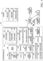
- FIG. 1 is a block diagram illustrating an electronic device 101 in a network environment 100 according to various embodiments.
- the electronic device 101 in the network environment 100 may communicate with an electronic device 102 via a first network 198 (e.g., a short-range wireless communication network), or at least one of an electronic device 104 or a server 108 via a second network 199 (e.g., a long-range wireless communication network).
- a first network 198 e.g., a short-range wireless communication network
- a second network 199 e.g., a long-range wireless communication network
- the electronic device 101 may communicate with the electronic device 104 via the server 108.
- the electronic device 101 may include a processor 120, memory 130, an input module 150, a sound output module 155, a display module 160, an audio module 170, a sensor module 176, an interface 177, a connecting terminal 178, a haptic module 179, a camera module 180, a power management module 188, a battery 189, a communication module 190, a subscriber identification module (SIM) 196, or an antenna module 197.
- at least one of the components e.g., the connecting terminal 178) may be omitted from the electronic device 101, or one or more other components may be added in the electronic device 101.
- some of the components e.g., the sensor module 176, the camera module 180, or the antenna module 197) may be implemented as a single component (e.g., the display module 160).
- the processor 120 may execute, for example, software (e.g., a program 140) to control at least one other component (e.g., a hardware or software component) of the electronic device 101 coupled with the processor 120, and may perform various data processing or computation. According to one embodiment, as at least part of the data processing or computation, the processor 120 may store a command or data received from another component (e.g., the sensor module 176 or the communication module 190) in volatile memory 132, process the command or the data stored in the volatile memory 132, and store resulting data in non-volatile memory 134.
- software e.g., a program 140
- the processor 120 may store a command or data received from another component (e.g., the sensor module 176 or the communication module 190) in volatile memory 132, process the command or the data stored in the volatile memory 132, and store resulting data in non-volatile memory 134.
- the processor 120 may include a main processor 121 (e.g., a central processing unit (CPU) or an application processor (AP)), or an auxiliary processor 123 (e.g., a graphics processing unit (GPU), a neural processing unit (NPU), an image signal processor (ISP), a sensor hub processor, or a communication processor (CP)) that is operable independently from, or in conjunction with, the main processor 121.
- a main processor 121 e.g., a central processing unit (CPU) or an application processor (AP)
- auxiliary processor 123 e.g., a graphics processing unit (GPU), a neural processing unit (NPU), an image signal processor (ISP), a sensor hub processor, or a communication processor (CP)
- the main processor 121 may be adapted to consume less power than the main processor 121, or to be specific to a specified function.
- the auxiliary processor 123 may be implemented as separate from, or as part of the main processor 121.
- the auxiliary processor 123 may control at least some of functions or states related to at least one component (e.g., the display module 160, the sensor module 176, or the communication module 190) among the components of the electronic device 101, instead of the main processor 121 while the main processor 121 is in an inactive (e.g., sleep) state, or together with the main processor 121 while the main processor 121 is in an active state (e.g., executing an application).
- the auxiliary processor 123 e.g., an image signal processor or a communication processor
- the auxiliary processor 123 may include a hardware structure specified for artificial intelligence model processing.
- An artificial intelligence model may be generated by machine learning. Such learning may be performed, e.g., by the electronic device 101 where the artificial intelligence is performed or via a separate server (e.g., the server 108). Learning algorithms may include, but are not limited to, e.g., supervised learning, unsupervised learning, semi-supervised learning, or reinforcement learning.
- the artificial intelligence model may include a plurality of artificial neural network layers.
- the artificial neural network may be a deep neural network (DNN), a convolutional neural network (CNN), a recurrent neural network (RNN), a restricted Boltzmann machine (RBM), a deep belief network (DBN), a bidirectional recurrent deep neural network (BRDNN), deep Q-network or a combination of two or more thereof but is not limited thereto.
- the artificial intelligence model may, additionally or alternatively, include a software structure other than the hardware structure.
- the memory 130 may store various data used by at least one component (e.g., the processor 120 or the sensor module 176) of the electronic device 101.
- the various data may include, for example, software (e.g., the program 140) and input data or output data for a command related thereto.
- the memory 130 may include the volatile memory 132 or the non-volatile memory 134.
- the program 140 may be stored in the memory 130 as software, and may include, for example, an operating system (OS) 142, middleware 144, or an application 146.
- OS operating system
- middleware middleware
- application application
- the input module 150 may receive a command or data to be used by another component (e.g., the processor 120) of the electronic device 101, from the outside (e.g., a user) of the electronic device 101.
- the input module 150 may include, for example, a microphone, a mouse, a keyboard, a key (e.g., a button), or a digital pen (e.g., a stylus pen).
- the sound output module 155 may output sound signals to the outside of the electronic device 101.
- the sound output module 155 may include, for example, a speaker or a receiver.
- the speaker may be used for general purposes, such as playing multimedia or playing record.
- the receiver may be used for receiving incoming calls. According to an embodiment, the receiver may be implemented as separate from, or as part of the speaker.
- the display module 160 may visually provide information to the outside (e.g., a user) of the electronic device 101.
- the display module 160 may include, for example, a display, a hologram device, or a projector and control circuitry to control a corresponding one of the display, hologram device, and projector.
- the display module 160 may include a touch sensor adapted to detect a touch, or a pressure sensor adapted to measure the intensity of force incurred by the touch.
- the audio module 170 may convert a sound into an electrical signal and vice versa. According to an embodiment, the audio module 170 may obtain the sound via the input module 150, or output the sound via the sound output module 155 or a headphone of an external electronic device (e.g., an electronic device 102) directly (e.g., wiredly) or wirelessly coupled with the electronic device 101.
- an external electronic device e.g., an electronic device 102
- directly e.g., wiredly
- wirelessly e.g., wirelessly
- the sensor module 176 may detect an operational state (e.g., power or temperature) of the electronic device 101 or an environmental state (e.g., a state of a user) external to the electronic device 101, and then generate an electrical signal or data value corresponding to the detected state.
- the sensor module 176 may include, for example, a gesture sensor, a gyro sensor, an atmospheric pressure sensor, a magnetic sensor, an acceleration sensor, a grip sensor, a proximity sensor, a color sensor, an infrared (IR) sensor, a biometric sensor, a temperature sensor, a humidity sensor, or an illuminance sensor.
- the interface 177 may support one or more specified protocols to be used for the electronic device 101 to be coupled with the external electronic device (e.g., the electronic device 102) directly (e.g., wiredly) or wirelessly.
- the interface 177 may include, for example, a high definition multimedia interface (HDMI), a universal serial bus (USB) interface, a secure digital (SD) card interface, or an audio interface.
- HDMI high definition multimedia interface
- USB universal serial bus
- SD secure digital
- a connecting terminal 178 may include a connector via which the electronic device 101 may be physically connected with the external electronic device (e.g., the electronic device 102).
- the connecting terminal 178 may include, for example, a HDMI connector, a USB connector, a SD card connector, or an audio connector (e.g., a headphone connector).
- the haptic module 179 may convert an electrical signal into a mechanical stimulus (e.g., a vibration or a movement) or electrical stimulus which may be recognized by a user via his tactile sensation or kinesthetic sensation.
- the haptic module 179 may include, for example, a motor, a piezoelectric element, or an electric stimulator.
- the power management module 188 may manage power supplied to the electronic device 101.
- the power management module 188 may be implemented as at least part of, for example, a power management integrated circuit (PMIC).
- PMIC power management integrated circuit
- the battery 189 may supply power to at least one component of the electronic device 101.
- the battery 189 may include, for example, a primary cell which is not rechargeable, a secondary cell which is rechargeable, or a fuel cell.
- the communication module 190 may support establishing a direct (e.g., wired) communication channel or a wireless communication channel between the electronic device 101 and the external electronic device (e.g., the electronic device 102, the electronic device 104, or the server 108) and performing communication via the established communication channel.
- the communication module 190 may include one or more communication processors that are operable independently from the processor 120 (e.g., the application processor (AP)) and supports a direct (e.g., wired) communication or a wireless communication.
- AP application processor
- the communication module 190 may include a wireless communication module 192 (e.g., a cellular communication module, a short-range wireless communication module, or a global navigation satellite system (GNSS) communication module) or a wired communication module 194 (e.g., a local area network (LAN) communication module or a power line communication (PLC) module).
- a wireless communication module 192 e.g., a cellular communication module, a short-range wireless communication module, or a global navigation satellite system (GNSS) communication module
- GNSS global navigation satellite system
- wired communication module 194 e.g., a local area network (LAN) communication module or a power line communication (PLC) module.
- LAN local area network
- PLC power line communication
- a corresponding one of these communication modules may communicate with the external electronic device 104 via the first network 198 (e.g., a short-range communication network, such as BluetoothTM, wireless-fidelity (Wi-Fi) direct, or infrared data association (IrDA)) or the second network 199 (e.g., a long-range communication network, such as a legacy cellular network, a 5G network, a next-generation communication network, the Internet, or a computer network (e.g., LAN or wide area network (WAN)).
- first network 198 e.g., a short-range communication network, such as BluetoothTM, wireless-fidelity (Wi-Fi) direct, or infrared data association (IrDA)
- the second network 199 e.g., a long-range communication network, such as a legacy cellular network, a 5G network, a next-generation communication network, the Internet, or a computer network (e.g., LAN or wide area network (WAN)).
- the wireless communication module 192 may support a 5G network, after a 4G network, and next-generation communication technology, e.g., new radio (NR) access technology.
- the NR access technology may support enhanced mobile broadband (eMBB), massive machine type communications (mMTC), or ultra-reliable and low-latency communications (URLLC).
- eMBB enhanced mobile broadband
- mMTC massive machine type communications
- URLLC ultra-reliable and low-latency communications
- the wireless communication module 192 may support a high-frequency band (e.g., the mmWave band) to achieve, e.g., a high data transmission rate.
- the wireless communication module 192 may support various technologies for securing performance on a high-frequency band, such as, e.g., beamforming, massive multiple-input and multiple-output (massive MIMO), full dimensional MIMO (FD-MIMO), array antenna, analog beam-forming, or large scale antenna.
- the wireless communication module 192 may support various requirements specified in the electronic device 101, an external electronic device (e.g., the electronic device 104), or a network system (e.g., the second network 199).
- the wireless communication module 192 may support a peak data rate (e.g., 20Gbps or more) for implementing eMBB, loss coverage (e.g., 164dB or less) for implementing mMTC, or U-plane latency (e.g., 0.5ms or less for each of downlink (DL) and uplink (UL), or a round trip of 1ms or less) for implementing URLLC.
- a peak data rate e.g., 20Gbps or more
- loss coverage e.g., 164dB or less
- U-plane latency e.g., 0.5ms or less for each of downlink (DL) and uplink (UL), or a round trip of 1ms or less
- the signal or the power may then be transmitted or received between the communication module 190 and the external electronic device via the selected at least one antenna.
- another component e.g., a radio frequency integrated circuit (RFIC)
- RFIC radio frequency integrated circuit
- the antenna module 197 may form a mmWave antenna module.
- the mmWave antenna module may include a printed circuit board, a RFIC disposed on a first surface (e.g., the bottom surface) of the printed circuit board, or adjacent to the first surface and capable of supporting a designated high-frequency band (e.g., the mmWave band), and a plurality of antennas (e.g., array antennas) disposed on a second surface (e.g., the top or a side surface) of the printed circuit board, or adjacent to the second surface and capable of transmitting or receiving signals of the designated high-frequency band.
- a RFIC disposed on a first surface (e.g., the bottom surface) of the printed circuit board, or adjacent to the first surface and capable of supporting a designated high-frequency band (e.g., the mmWave band)
- a plurality of antennas e.g., array antennas
- At least some of the above-described components may be coupled mutually and communicate signals (e.g., commands or data) therebetween via an inter-peripheral communication scheme (e.g., a bus, general purpose input and output (GPIO), serial peripheral interface (SPI), or mobile industry processor interface (MIPI)).
- an inter-peripheral communication scheme e.g., a bus, general purpose input and output (GPIO), serial peripheral interface (SPI), or mobile industry processor interface (MIPI)
- commands or data may be transmitted or received between the electronic device 101 and the external electronic device 104 via the server 108 coupled with the second network 199.
- Each of the electronic devices 102 or 104 may be a device of a same type as, or a different type, from the electronic device 101.
- all or some of operations to be executed at the electronic device 101 may be executed at one or more of the external electronic devices 102, 104, or 108. For example, if the electronic device 101 should perform a function or a service automatically, or in response to a request from a user or another device, the electronic device 101, instead of, or in addition to, executing the function or the service, may request the one or more external electronic devices to perform at least part of the function or the service.
- the one or more external electronic devices receiving the request may perform the at least part of the function or the service requested, or an additional function or an additional service related to the request, and transfer an outcome of the performing to the electronic device 101.
- the electronic device 101 may provide the outcome, with or without further processing of the outcome, as at least part of a reply to the request.
- a cloud computing, distributed computing, mobile edge computing (MEC), or client-server computing technology may be used, for example.
- the electronic device 101 may provide ultra low-latency services using, e.g., distributed computing or mobile edge computing.
- the external electronic device 104 may include an internet-of-things (IoT) device.
- the server 108 may be an intelligent server using machine learning and/or a neural network.
- the external electronic device 104 or the server 108 may be included in the second network 199.
- the electronic device 101 may be applied to intelligent services (e.g., smart home, smart city, smart car, or healthcare) based on 5G communication technology or IoT-related technology.
- the electronic device may be one of various types of electronic devices.
- the electronic devices may include, for example, a portable communication device (e.g., a smartphone), a computer device, a portable multimedia device, a portable medical device, a camera, a wearable device, or a home appliance. According to an embodiment of the disclosure, the electronic devices are not limited to those described above.
- each of such phrases as “A or B,” “at least one of A and B,” “at least one of A or B,” “A, B, or C,” “at least one of A, B, and C,” and “at least one of A, B, or C,” may include any one of, or all possible combinations of the items enumerated together in a corresponding one of the phrases.
- such terms as “1st” and “2nd,” or “first” and “second” may be used to simply distinguish a corresponding component from another, and does not limit the components in other aspect (e.g., importance or order).
- an element e.g., a first element
- the element may be coupled with the other element directly (e.g., wiredly), wirelessly, or via a third element.
- module may include a unit implemented in hardware, software, or firmware, and may interchangeably be used with other terms, for example, “logic,” “logic block,” “part,” or “circuitry”.
- a module may be a single integral component, or a minimum unit or part thereof, adapted to perform one or more functions.
- the module may be implemented in a form of an application-specific integrated circuit (ASIC).
- ASIC application-specific integrated circuit
- Various embodiments as set forth herein may be implemented as software (e.g., the program 140) including one or more instructions that are stored in a storage medium (e.g., internal memory 136 or external memory 138) that is readable by a machine (e.g., the electronic device 101).
- a processor e.g., the processor 120
- the machine e.g., the electronic device 101
- the one or more instructions may include a code generated by a complier or a code executable by an interpreter.
- the machine-readable storage medium may be provided in the form of a non-transitory storage medium.
- non-transitory simply means that the storage medium is a tangible device, and does not include a signal (e.g., an electromagnetic wave), but this term does not differentiate between where data is semi-permanently stored in the storage medium and where the data is temporarily stored in the storage medium.
- a method may be included and provided in a computer program product.
- the computer program product may be traded as a product between a seller and a buyer.
- the computer program product may be distributed in the form of a machine-readable storage medium (e.g., compact disc read only memory (CD-ROM)), or be distributed (e.g., downloaded or uploaded) online via an application store (e.g., PlayStore TM ), or between two user devices (e.g., smart phones) directly. If distributed online, at least part of the computer program product may be temporarily generated or at least temporarily stored in the machine-readable storage medium, such as memory of the manufacturer's server, a server of the application store, or a relay server.
- CD-ROM compact disc read only memory
- an application store e.g., PlayStore TM
- two user devices e.g., smart phones
- each component e.g., a module or a program of the above-described components may include a single entity or multiple entities, and some of the multiple entities may be separately disposed in different components. According to various embodiments, one or more of the above-described components may be omitted, or one or more other components may be added. Alternatively or additionally, a plurality of components (e.g., modules or programs) may be integrated into a single component. In such a case, according to various embodiments, the integrated component may still perform one or more functions of each of the plurality of components in the same or similar manner as they are performed by a corresponding one of the plurality of components before the integration.
- operations performed by the module, the program, or another component may be carried out sequentially, in parallel, repeatedly, or heuristically, or one or more of the operations may be executed in a different order or omitted, or one or more other operations may be added.
- FIG. 2 is a perspective view of an electronic device 200 in an unfolded state according to an embodiment of the disclosure.
- FIG. 3 is a perspective view of the electronic device 200 in an unfolded state according to an embodiment of the disclosure.
- FIG. 2 may be a view of one lateral surface (e.g., a front surface) of the electronic device 200 as viewed obliquely
- FIG. 3 may be a view of another lateral surface (e.g., a rear surface) of the electronic device 200 as viewed obliquely.
- the components described with reference to FIGS. 2 and 3 may be partially or entirely the same as the components described with reference to FIG. 1 .
- the components described with reference to FIGS. 2 and 3 may be partially or entirely the same as the components described with reference to FIGS. 4 to 17D .
- a state in which the electronic device 200 is unfolded may be defined as a "first state".
- the electronic device 200 may include a housing 201.
- the electronic device 200 may include a display 202.
- the housing 201 may form a space in which the display 202 is disposed.
- the display 202 may be a flexible display 202. At least a part of the display 202 may be folded or unfolded.
- the housing 201 may include a first housing 210.
- the housing 201 may include a second housing 220.
- the housing 201 may include a third housing 230.
- the first housing 210 may be disposed between the second housing 220 and the third housing 230.
- the second housing 220 may be rotatably coupled to the first housing 210.
- the third housing 230 may be rotatably coupled to the first housing 210.
- the display 202 may include a first display area 202a corresponding to the first housing 210, a second display area 202b corresponding to the second housing 220, and a third display area 202c corresponding to the third housing 230.
- the electronic device 200 may include supports 240, 250, and 260.
- the supports 240, 250, and 260 may be disposed between the housing 201 and the display 202.
- the supports 240, 250, and 260 may be coupled to the housing 201 and may support the display 202.
- the supports 240, 250, and 260 may be arranged to surround the edge of the display 202.
- the supports 240, 250, and 260 may extend along the circumference of the housing 201.
- the supports 240, 250, and 260 may include a first support 240 disposed in the first housing 210, a second support 250 disposed in the second housing 220, and a third support 260 disposed in the third housing 230.
- Each of the supports 240, 250, and 260 may be referred to as a "body”. Each of the supports 240, 250, and 260 may be referred to as a "frame”. Each of the supports 240, 250, and 260 may be referred to as a "sealing member”. Each of the supports 240, 250, and 260 may be referred to as a "peripheral part”. Each of the supports 240, 250, and 260 may be referred to as a "circumferential part”. Each of the supports 240, 250, and 260 may be referred to as a "peripheral structure”. Each of the supports 240, 250, and 260 may be referred to as a "circumferential structure”.
- the supports 240, 250, and 260 may be disposed between the housings 210, 220, and 230 and the display 202, respectively.
- the supports 240, 250, and 260 may reduce friction between the housings 210, 220, and 230 and the display 202.
- Each of the supports 240, 250, and 260 may be referred to as a "buffering member".
- the supports 240, 250, and 260 may include the first support 240.
- the first support 240 may be disposed between the first housing 210 and the display 202.
- the first support 240 may be disposed along the edge of the first housing 210.
- the first support 240 may include a (1-1)th support 241 and a (1-2)th support 242. At least a part of the display 202 may be disposed between the (1-1)th support 241 and the (1-2)th support 242.
- the (1-1)th support 241 may be disposed in one end portion of the first housing 210, and the (1-2)th support body 242 may be disposed in the other end portion of the first housing 210.
- Each of the first, second, and third supports 240, 250, and 260 may be referred to as a "support”.
- Each of the supports 240, 250, and 260 may be referred to as "deco”, a “finishing member”, or a "non-conductive member”.
- the supports 240, 250, and 260 may include the second support 250.
- the second support 250 may be disposed between the second housing 220 and the display 202.
- the second support 250 may be disposed along the edge of the second housing 220.
- the second support 250 may include a (2-1)th support 251, a (2-2)th support 252, and a (2-3)th support 253. At least a part of the display 202 may be disposed between the (2-2)th support 252 and the (2-3)th support 253.
- the (2-1)th support 251 may connect the (2-2)th support 252 and the (2-3)th support 253.
- the (2-1)th support 251 may extend along the edge (e.g., an edge 222 of FIG. 3 ) of the second housing 220.
- the (2-1)th support 251 may be disposed between the display 202 and the edge 222 of the second housing 220.
- the (2-1)th support 251 may be referred to as a "support frame” or a "first support frame”.
- Each of the (2-2)th support 252 and the (2-3)th support 253 may be referred to as a "second support frame”.
- the supports 240, 250, and 260 may include the third support 260.
- the third support 260 may be disposed between the third housing 230 and the display 202.
- the third support 260 may be disposed along the edge of the third housing 230.
- the third support 260 may include a (3-1)th support 261, a (3-2)th support 262, and a (3-3)th support 263. At least a part of the display 202 may be disposed between the (3-2)th support 262 and the (3-3)th support 263.
- the (3-1)th support 261 may connect the (3-2)th support 262 and the (3-3)th support 263.
- the (3-1)th support 261 may extend along the edge (e.g., an edge 232 of FIG.
- the (3-1)th support 261 may be disposed between the display 202 and the edge 232 of the third housing 230.
- the (3-1)th support 261 may be referred to as a "support frame” or a "first support frame”.
- Each of the (3-2)th support 262 and the (3-3)th support 263 may be referred to as a "second support frame”.
- the first housing 210 may include a (1-1)th side portion 211 and a (1-2)th side portion 212.
- the (1-1)th side portion 211 and the (1-2)th side portion 212 may form opposite lateral surfaces of the first housing 210, respectively.
- the second housing 220 may be coupled with the (1-1)th side portion 211.
- the third housing 230 may be coupled with the (1-2)th side portion 212.
- the (1-1)th side portion 211 may be referred to as a "first coupling portion”.
- the (1-2)th side portion 212 may be referred to as a "second coupling portion".
- the (1-1)th side portion 211 may be referred to as a "first portion”.
- the (1-2)th side portion 212 may be referred to as a "second portion".
- the second housing 220 may include a (2-1)th side portion 221 and a (2-2)th side portion 222.
- the (2-1)th side portion 221 and the (2-2)th side portion 222 may form opposite lateral surfaces of the second housing 220, respectively.
- the (2-1)th side portion 221 may be coupled with the first housing 210.
- the (2-2)th side portion 222 may form a lateral surface of the housing 201.
- the (2-2)th side portion 222 may be referred to as an "edge”.
- the (2-1)th side portion 221 may be referred to as a "third side portion”.
- the (2-2)th side portion 222 may be referred to as a "fourth side portion".
- the third housing 230 may include a (3-1)th side portion 231 and a (3-2)th side portion 232.
- the (3-1)th side portion 231 and the (3-2)th side portion 232 may form opposite lateral surfaces of the third housing 230, respectively.
- the (3-1)th side portion 231 may be coupled with the first housing 210.
- the (3-2)th side portion 232 may form a lateral surface of the housing 201.
- the (3-2)th side portion 232 may be referred to as an "edge”.
- the (3-1)th side portion 231 may be referred to as a "fifth side portion”.
- the (3-2)th side portion 232 may be referred to as a "sixth side portion".
- the electronic device 200 may include a first hinge 270 and a second hinge 280.
- the first hinge 270 may be disposed between the first housing 210 and the second housing 220.
- the first hinge 270 may be disposed between the (1-1)th side portion 211 and the (2-1)th side portion 221.
- the first hinge 270 may rotatably connect the first housing 210 and the second housing 220.
- the second hinge 280 may be disposed between the first housing 210 and the third housing 230.
- the second hinge 280 may be disposed between the (1-2)th side portion 212 and the (3-1)th side portion 231.
- the second hinge 280 may rotatably connect the first housing 210 and the third housing 230.
- FIG. 4 is a perspective view of the electronic device 200 in a folded state according to an embodiment of the disclosure.
- FIG. 5 is a lateral view of the electronic device 200 of FIG. 4 viewed from one direction (e.g., -Y direction) toward another direction (e.g., +Y direction).
- the components described with reference to FIGS. 4 and 5 may be partially or entirely the same as the components described with reference to FIGS. 1 to 3 .
- the components described with reference to FIGS. 4 and 5 may be partially or entirely the same as the components described with reference to FIGS. 6 to 17D .
- the second housing 220 may be rotated with respect to the first housing 210.
- the first hinge 270 may provide a rotation center to the second housing 220.
- the first hinge 270 may connect the (1-1)th side portion 211 and the (2-1)th side portion 221.
- the third housing 230 may be rotated with respect to the first housing 210.
- the second hinge 280 may provide a rotation center to the third housing 230.
- the second hinge 280 may connect the (1-2)th side portion 212 and the (3-1)th side portion 231.
- each of the first, second, and third housings 210, 220, and 230 may be arranged in one direction (e.g., +Y direction).
- the third housing 230 may be disposed above the first housing 210, and the second housing 220 may be disposed above the third housing 230.
- the third housing 230 may be disposed between the first housing 210 and the second housing 220.
- the electronic device 200 may include an antenna 223.
- the antenna 223 may be configured on the edge 222 of the second housing 220.
- the antenna 223 may be integrated with the second housing 220 and may be a part of the edge 222.
- the antenna 223 may be manufactured separately from the second housing 220 and may be coupled to the edge 222 of the second housing 220.
- the antenna 223 may be referred to as a "first conductive portion".
- the antenna 223 may include a metal material.
- the edge 222 of the second housing 220 may be an area of the second housing 220 where a screen of the flexible display 202 overlaps a portion which is not visible from the outside of a housing (e.g., the second housing 220) when the flexible display 202 is viewed from a screen display direction (e.g., +Z direction).
- the edge 222 of the second housing 220 may include a bezel portion (e.g., a second support portion 257 of FIG. 8 ) of the second housing 220 and the antenna 223.
- the antenna 223 in a state in which the electronic device 200 is folded, the antenna 223 may be spaced apart from the second hinge 280. One surface of the antenna 223 may face the second hinge 280.
- the width of the first hinge 270 may be larger than the width of the second hinge 280.
- the length that the first hinge 270 extends in the +Z direction may be greater than the length that the second hinge 280 extends in the +Z direction.
- the antenna 223 may include a first antenna portion 2231, a second antenna portion 2232, and a third antenna portion 2233.
- the first, second, and third antenna portions 2231, 2232, and 2233 may be spaced apart from each other along the edge 222 of the second housing 220.
- Each of the first, second, and third antenna portions 2231, 2232, and 2233 may include a conductive material.
- the antenna 223 may include a first segment portion 2234 and a second segment portion 2235.
- the first segment portion 2234 may be disposed between the first antenna portion 2231 and the second antenna portion 2232.
- the second segment portion 2235 may be disposed between the first antenna portion 2231 and the third antenna portion 2233.
- the electronic device 200 may include a first antenna 215, a second antenna 225, and a third antenna 235.
- the first antenna 215 may form a part of the first housing 210.
- the first antenna 215 may form at least a part of the surface of the first housing 210.
- the second antenna 225 may form a part of the second housing 220.
- the second antenna 225 may form at least a part of the surface of the second housing 220.
- the third antenna 235 may form a part of the third housing 230.
- the third antenna 235 may form at least a part of the surface of the third housing 230.
- the first antenna 215 may include a (1-1)th antenna portion 2151, a (1-2)th antenna portion 2152, and a (1-3)th antenna portion 2153.
- the (1-1)th antenna portion 2151 may be disposed between the (1-2)th antenna portion 2152 and the (1-3)th antenna portion 2153.
- the first antenna 215 may include a (1-1)th segment portion 2154 and a (1-2)th segment portion 2155.
- the (1-1)th antenna portion 2151 and the (1-2)th antenna portion 2152 may be spaced apart from each other, and the (1-1)th segment portion 2154 may be disposed between the (1-1)th antenna portion 2151 and the (1-2)th antenna portion 2152.
- the (1-1)th antenna portion 2151 and the (1-3)th antenna portion 2153 may be spaced apart from each other, and the (1-2)th segment portion 2155 may be disposed between the (1-1)th antenna portion 2151 and the (1-3)th antenna portion 2153.
- the second antenna 225 may include a (2-1)th antenna portion 2251, a (2-2)th antenna portion 2252, and a (2-3)th antenna portion 2253.
- the (2-1)th antenna portion 2251 may be disposed between the (2-2)th antenna portion 2252 and the (2-3)th antenna portion 2253.
- the second antenna 225 may include a (2-1)th segment portion 2254 and a (2-2)th segment portion 2255.
- the (2-1)th antenna portion 2251 and the (2-2)th antenna portion 2252 may be spaced apart from each other, and the (2-1)th segment portion 2254 may be disposed between the (2-1)th antenna portion 2251 and the (2-2)th antenna portion 2252.
- the (2-1)th antenna portion 2251 and the (2-3)th antenna portion 2253 may be spaced apart from each other, and the (2-2)th segment portion 2255 may be disposed between the (2-1)th antenna portion 2251 and the (2-3)th antenna portion 2253.
- the third antenna 235 may include a (3-1)th antenna portion 2351, a (3-2)th antenna portion 2352, and a (3-3)th antenna portion 2353.
- the (3-1)th antenna portion 2351 may be disposed between the (3-2)th antenna portion 2352 and the (3-3)th antenna portion 2353.
- the third antenna 235 may include a (3-1)th segment portion 2354 and a (3-2)th segment portion 2355.
- the (3-1)th antenna portion 2351 and the (3-2)th antenna portion 2352 may be spaced apart from each other, and the (3-1)th segment portion 2354 may be disposed between the (3-1)th antenna portion 2351 and the (3-2)th antenna portion 2352.
- the (3-1)th antenna portion 2351 and the (3-3)th antenna portion 2353 may be spaced apart from each other, and the (3-2)th segment portion 2355 may be disposed between the (3-1)th antenna portion 2351 and the (3-3)th antenna portion 2353.
- the first housing 210, the second housing 220, and the third housing 230 may be aligned with each other.
- the first housing 210, the third housing 230, and the second housing 220 may be aligned in one direction (e.g., +Z direction) in the order described.
- the first antenna 215, the second antenna 225, and the third antenna 235 may be aligned with each other.
- the first antenna 215, the third antenna 235, and the second antenna 225 may be aligned in one direction (e.g., +Z direction) in the order described.
- the first antenna 215, the second antenna 225, and the third antenna 235 may be aligned with each other in a direction (e.g., +Z direction) in which the housings 210, 220, and 230 are stacked.
- the (1-1)th antenna portion 2151, the (2-1)th antenna portion 2251, and the (3-1)th antenna portion 2351 may be aligned in a first direction (e.g., +Z direction).
- the (1-2)th antenna portion 2152, the (2-2)th antenna portion 2252, and the (3-2)th antenna portion 2352 may be aligned in the first direction (e.g., +Z direction).
- the (1-3)th antenna portion 2153, the (2-3)th antenna portion 2253, and the (3-3)th antenna portion 2353 may be aligned in the first direction (e.g., +Z direction).
- the (1-1)th segment portion 2154, the (2-1)th segment portion 2254, and the (3-1)th segment portion 2354 may be aligned in the first direction (e.g., +Z direction).
- the (1-2)th segment portion 2155, the (2-2)th segment portion 2255, and the (3-2)th segment portion 2355 may be aligned in the first direction (e.g., +Z direction).
- FIG. 6 is an exploded view of a part of the electronic device 200 according to an embodiment of the disclosure.
- FIG. 6 illustrates a state in which a display (e.g., the display 202 of FIG. 2 ) is not shown.
- the components described with reference to FIG. 6 may be partially or entirely the same as the components described with reference to FIGS. 1 to 5 .
- the components described with reference to FIG. 6 may be partially or entirely the same as the components described with reference to FIGS. 7 to 17D .
- the first housing 210 may include a first housing body 216.
- the first housing 210 may include a first cover 217.
- the first housing body 216 and the first cover 217 may be coupled with each other.
- At least a part of a display e.g., the display 202 of FIG. 2
- At least a part of a second display e.g., a second display 206 of FIG. 8
- the second housing 220 may include a second housing body 226.
- the second housing 220 may include a second cover 227.
- the second housing body 226 and the second cover 227 may be coupled with each other.
- At least a part of the display e.g., the display 202 of FIG. 2
- At least a part of the second display e.g., the second display 206 of FIG. 8
- An antenna e.g., the antenna 223 of FIG. 5
- the third housing 230 may include a third housing body 236.
- the third housing 230 may include a third cover 237.
- the third housing body 236 and the third cover 237 may be coupled with each other.
- At least a part of the display e.g., the display 202 of FIG. 2
- At least a part of the second display e.g., the second display 206 of FIG. 8
- the first hinge 270 may rotatably connect the first housing body 216 and the second housing body 226.
- the second hinge 280 may rotatably connect the first housing body 216 and the third housing body 236.
- the electronic device 200 may include a battery 203.
- the battery 203 may supply power to electrical components (e.g., the display 202, the second display 206, and a circuit board 204) of the electronic device 200.
- the battery 203 may be disposed between the housing bodies 216, 226, and 236 and the covers 217, 227, and 237.
- the electronic device 200 may include a circuit board 204.
- the circuit board 204 may be electrically connected to electrical components (e.g., the display 202, the second display 206, an antenna circuit 2236, and the battery 203) of the electronic device 200.
- the circuit board 204 may be disposed between the housing bodies 216, 226, and 236 and the covers 217, 227, and 237.
- the electronic device 200 may include a camera assembly 205.
- the camera assembly 205 may be disposed between the housing bodies 216, 226, and 236 and the covers 217, 227, and 237.
- the electronic device 200 may include a flexible circuit board 209.
- the flexible circuit board 209 may be connected to the circuit board 204.
- the electronic device 200 may include a second conductive portion 233.
- the second conductive portion 233 may be a part of the third housing 230.
- the second conductive portion 233 may be disposed between the first housing 210 and the second housing 220 in a state in which the electronic device 200 is folded.
- the second conductive portion 233 may face the first hinge 270 in a state in which the electronic device 200 is folded.
- FIG. 7A is a view illustrating a state in which a part of a housing 301 of the electronic device 101 is folded.
- FIG. 7A may be a view illustrating the electronic device 101 viewed in a predetermined direction (e.g., the +Y direction in FIG. 4 ) in a state in which the housing 301 is folded.
- FIG. 7B is a view illustrating the movement of a third housing 330 among structures of FIG. 7A .
- FIG. 8 is a view conceptually illustrating the connection relationship between components 360, 371, 372, 373, 381, and 382 of the electronic device 101.
- the components described with reference to FIGS. 7A, 7B , and 8 may be partially or entirely the same as the components described with reference to FIGS. 1 to 6 .
- the components described with reference to FIGS. 7A, 7B , and 8 may be partially or entirely the same as the components described with reference to FIGS. 9 to 17D .
- the above description of the components e.g., the housing 201, the first housing 210, the second housing 220, the third housing 230, the first hinge 270, and the second hinge 280
- the housing 301, the first housing 310, the second housing 320, the third housing 330, the first hinge 340, and the second hinge 350 may be equally applicable to the description of the above-described components (e.g., the housing 301, the first housing 310, the second housing 320, the third housing 330, the first hinge 340, and the second hinge 350).
- the electronic device 101 may include a display 302 stably placed on the housing 301.
- the display 302 may include a first display area 3021 corresponding to the first housing 310, a second display area 3022 corresponding to the second housing 320, and a third display area 3023 corresponding to the third housing 330.
- the first, second, and third display areas 3021, 3022, and 3023 may be integrally configured.
- the display 302 may be a flexible display, at least a part of which is folded or unfolded.
- the above description of the display 202 with reference to FIGS. 1 to 6 may be equally applicable to the description of the display 302.
- the electronic device 101 may include a second display 390.
- the second display 390 may be disposed in the second housing 320.
- the second display 390 may move together with the second housing 320.
- the second display area 3022 may be disposed on a first surface of the second housing 320, and the second display 390 may be disposed on a second surface of the second housing 320, the second surface being opposite to the first surface.
- the electronic device 101 may include a processor 360.
- the processor 360 may be disposed inside the housing 301.
- the processor 360 may be disposed inside the first housing 310.
- the above description of the processor 120 with reference to FIG. 1 may be equally applicable to the description of the processor 360.
- the electronic device 101 may include a sensor 370.
- the sensor 370 may be a 6-axis sensor, an angle sensor, a position sensor, an acceleration sensor, a gyro sensor, or a proximity sensor.
- the sensor 370 may sense an angle at which the housing 301 is folded or unfolded.
- the sensor 370 may include a plurality of sensors 371, 372, and 373. Each of the plurality of sensors 371, 372, and 373 may be disposed in one of the first, second, and third housings 310, 320, and 330.
- the sensor 370 may include a first sensor 371, a second sensor 372, and a third sensor 373.
- Each of the first, second, and third sensors 371, 372, and 373 may be referred to as a "first sensor” or a "second sensor”.
- the first sensor 371 may be disposed inside the first housing 310.
- the second sensor 372 may be disposed inside the second housing 320.
- the third sensor 373 may be disposed inside the third housing 330.
- the processor 360 may be electrically connected to the sensor 370.
- the processor 360 may receive a signal detected by the sensor 370.
- the processor 360 may be electrically connected to each of the first, second, and third sensors 371, 372, and 373.
- the processor 360 may receive signals generated from the first, second, and third sensors 371, 372, and 373.
- the processor 360 may determine a first angle between the first housing 310 and the second housing 320 or a second angle between the first housing 310 and the third housing 330, based on the signals generated from the first, second, and third sensors 371, 372, and 373.
- the electronic device 101 may include an actuator 380.
- the actuator 380 may generate a vibration.
- the actuator 380 may transmit a vibration to the housing 301 and the display 302.
- the actuator 380 may provide a haptic function of the electronic device 101.
- the actuator 380 may be referred to as a "vibration member”.
- the actuator 380 may be referred to as a "haptic device”.
- An operation manner of the actuator 380 is not limited to the above description.
- the actuator 380 may perform operations such as screen display, light emission, or sound in addition to vibration.
- the actuator 380 may include a plurality of actuators 380. Each of the plurality of actuators 380 may be disposed in one of the second housing 320 and the third housing 330.
- the actuator 380 may include a first actuator 381 disposed in the second housing 320 and a second actuator 382 disposed in the third housing 330.
- the first actuator 381 may transmit a vibration to the second housing 320 and the second display area 3022.
- the second actuator 382 may transmit a vibration to the third housing 330 and the third display area 3023.
- the processor 360 may be electrically connected to the actuator 380.
- the processor 360 may control the driving of the actuator 380.
- the processor 360 may be electrically connected to each of the first and second actuators 381 and 382.
- the processor 360 may determine a first angle between the first housing 310 and the second housing 320 or a second angle between the first housing 310 and the third housing 330, based on signals generated from the first, second, and third sensors 371, 372, and 373.
- the processor 360 may control the driving of the actuator 380, based on the first angle and the second angle.
- the second housing 320 may be rotated with respect to the first housing 310.
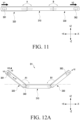
- a first angle A may be formed between the first housing 310 and the second housing 320.
- the first angle A may be defined as an angle at which the second housing 320 is tilted with respect to the first housing 310.
- the first angle A may be defined as an angle at which the second display area 3022 is bent with respect to the first display area 3021.
- the first angle A may be defined as an angle formed between the first housing 310 and the second housing 320.
- the first display area 3021 may form a base surface (BS), and the first angle A may be defined as an angle at which the second housing 320 is inclined with respect to the base surface (BS).
- the third housing 330 may be rotated with respect to the first housing 310.
- a second angle B may be formed between the first housing 310 and the third housing 330.
- the second angle B may be defined as an angle at which the third housing 330 is tilted with respect to the first housing 310.
- the second angle B may be defined as an angle at which the third display area 3023 is bent with respect to the first display area 3021.
- the second angle B may be defined as an angle formed between the first housing 310 and the third housing 330.
- the first display area 3021 may form a base surface (BS), and the second angle B may be defined as an angle at which the third housing 330 is inclined with respect to the base surface (BS).
- a relative angle C may be formed between the second housing 320 and the third housing 330.
- the relative angle C may be an included angle between the second housing 320 and the third housing 330.
- the electronic device 101 may include two housings (e.g., a first housing 710 and a second housing 720 of FIG. 17A ) and one hinge (e.g., a hinge 730 of FIG. 17A ).
- the electronic device 101 may include the second housing 320, the third housing 330, and the hinge 340 which connects the second housing 320 and the third housing 330.
- the second housing 320 may be referred to as a "first housing”
- the third housing 330 may be referred to as a "second housing”.
- the processor 360 may be disposed in the first housing 320 or the second housing 330, and may receive signals from the plurality of sensors 372 and 373 to control the actuators 381 and 382.
- FIG. 9 is a block diagram illustrating a control method of the electronic device 101 according to an embodiment of the disclosure.
- FIG. 10A is a conceptual diagram illustrating a method of determining an angle (e.g., the first angle A) between housings (e.g., the first housing 310 and the second housing 320) according to an embodiment of the disclosure.
- FIG. 10B is a conceptual diagram illustrating a method of determining an angle (e.g., the first angle A) between housings (e.g., the first housing 310 and the second housing 320) according to an embodiment of the disclosure.
- the components described with reference to FIGS. 9 to 10B may be partially or entirely the same as the components described with reference to FIGS. 1 to 8 .
- the components described with reference to FIGS. 9 to 10B may be partially or entirely the same as the components described with reference to FIGS. 11 to 17D .
- a control method of the electronic device 101 may include an operation (P100) of determining a first angle A between the first housing 310 and the second housing 320.
- the processor 360 may determine a first angle A, based on information sensed by the first sensor 371 and the second sensor 372.
- control method of the electronic device 101 may include an operation (P200) of determining a second angle B between the first housing 310 and the third housing 330.
- the processor 360 may determine a second angle B, based on information sensed by the first sensor 371 and the third sensor 373.
- control method of the electronic device 101 may include an operation (P300) of determining a relative angle between the second housing 320 and the third housing 330.
- the processor 360 may determine a relative angle between the second housing 320 and the third housing 330, based on the first angle A and the second angle B.
- control method of the electronic device 101 may include an operation (P400) of comparing the relative angle between the second housing 320 and the third housing 330 with a preconfigured reference value.
- the processor 360 may compare the relative angle with the reference value.
- the control method of the electronic device 101 may include an operation (P500) of controlling a phase of a signal input to the actuator 380.
- the processor 360 may control an operation of the actuator 380 and input a signal for operating the actuator 380.
- the processor 360 may control a phase of a signal input to the actuator 360.
- the control method of the electronic device 101 may include an operation (P600) of driving the actuator 380.
- the processor 360 may drive the actuator 380.
- the processor 360 may transmit a signal for driving the actuator 380 to the actuator 380.
- the processor 360 may adjust a phase of the signal, and then transmit the phase-adjusted signal to the actuator 380.
- control method of the electronic device 101 may include operations (P100 and P200) of determining angles A and B formed by the housing 301.
- the processor 360 may determine angles A and B formed by the housing 301.
- a first housing 910 and a second housing 920 may be rotatably coupled with each other through a hinge 930.
- An angle ⁇ 3 may be formed between the first housing 910 and the second housing 920.
- An included angle ⁇ 3 between the first housing 910 and the second housing 920 may be determined by an angle ⁇ 1 of the first housing 910 with respect to a base surface and an angle ⁇ 2 of the second housing 920 with respect to the base surface.
- the included angle ⁇ 3 may be determined as a value obtained by subtracting the angle ⁇ 1 of the first housing 910 and the angle ⁇ 2 of the second housing 920 from 180 degrees, as described in Equation 1 below.
- the first housing 910 may include a first sensor 911
- the second housing 920 may include a second sensor 921.
- the first sensor 911 and the second sensor 21 may sense the angles ⁇ 1 and ⁇ 2.
- ⁇ 3 180 ⁇ ⁇ 1 + ⁇ 2
- the angles ⁇ 1 and ⁇ 2 of the housings 910 and 920 with respect to the base surface may be determined as shown in FIG. 10B .
- the first housing 910 may include a first sensor block 911a
- the second housing 920 may include a second sensor block 911b.
- the first sensor block 911a and the second sensor block 911b may be 6-axis sensors.
- the first sensor block 911a and the second sensor block 911b may be acceleration sensors.
- the first sensor block 911a may be disposed inside a first sensor (e.g., the first sensor 371 of FIG. 7 ).
- the second sensor block 911b may be disposed inside a second sensor (e.g., the second sensor 372 of FIG. 7 ).
- the angles ⁇ 1 and ⁇ 2 of the housings 910 and 920 with respect to the base surface may be determined by a manner of calculating an angle ⁇ at which the sensor block 911b is tilted shown in FIG. 10B .
- the sensor block 911a may have a first area value Y in a first direction and a second area value Z in a second direction.
- Gravitational acceleration g may act on the sensor block 911a.
- a gravitational acceleration distribution f(Y) in the first direction may be formed, and a gravitational acceleration distribution f(Z) in the second direction may be formed.
- a first gravitational acceleration area Y1 in the first direction may be calculated by integrating gyro data f(Y)Y) which is obtained by multiplying the first area value Y in the first direction in the local unit by the gravitational acceleration distribution f(Y).
- a second gravitational acceleration area Z1 in the second direction may be calculated by integrating gyro data f(Z)Z) which is obtained by multiplying the second area value Z in the second direction in the local unit by the gravitational acceleration distribution f(Z).
- the angle ⁇ at which the sensor block 911b is tilted may be calculated by Equation 2 and Equation 3 below.
- the processor 360 may determine a first angle A and a second angle B by using the manner described with reference to FIGS. 10A and 10B .
- the processor 360 may perform the operations (P100 and P200) of determining the first and second angles A and B, and may determine the first and second angles A and B through the method of calculating the included angle ⁇ 3 shown in FIG. 10A .
- the processor 360 may calculate a relative angle C between the second housing 320 and the third housing 330, based on the determined first and second angles A and B.
- the processor 360 may calculate the relative angle by using Equation 4 below.
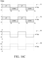
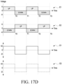
- the processor (e.g., 360 in FIGS. 1 to 17D ) according to an embodiment of the disclosure may be configured to change one of the first phase and the second phase into an opposite phase.
- the third operation may include an operation of changing one of the first vibration (e.g., V1 in FIGS. 1 to 17D ) and the second vibration (e.g., V2 in FIGS. 1 to 17D ) into an opposite phase.
- the first vibration e.g., V1 in FIGS. 1 to 17D
- the second vibration e.g., V2 in FIGS. 1 to 17D
- a foldable electronic device (101) comprises: a first housing (310); a second housing (320) disposed rotatably with respect to the first housing (310); a third housing (330) disposed rotatably with respect to the first housing (310) and spaced apart from the second housing (320); a first hinge (340) connecting the first housing (310) and the second housing (320); a second hinge (350) connecting the first housing (310) and the third housing (330); a first actuator (381) disposed in the second housing (320) and configured to generate a first vibration (V1); a second actuator (382) disposed in the third housing (330) and configured to generate a second vibration (V2); and a processor (360) configured to: determine a relative angle (C) between the second housing (320) and the third housing (330) based on a first angle (A) between the first housing (310) and the second housing (320), and a second angle (B) between the first housing (310) and the third housing (330), obtained using a pluralit
- the relative angle (C) corresponds to an absolute value of difference between a sum of the first angle (A) and the second angle (B) and 180 degree.
- the processor (360) is configured to transmit a first signal to the first actuator (381) and a second signal to the second actuator (382), and/or the processor (360) is configured to change one of a phase of the first signal or a phase of the second signal based on the relative angle (C).
- the processor (360) is configured to change one of the phase of the first signal or the phase of the second signal to an opposite phase.
- a direction of the first vibration (V1) is parallel with respect to the second housing (320), and a direction of the second vibration (V2) is parallel with respect to the third housing (330).
- the processor (360) is configured to control the first vibration (V1) or the second vibration (V2) when a first vector component in a first direction of the first vibration (V1) and a second vector component in the first direction are opposite to each other.
- An electronic device (101) comprises: a foldable housing (301, 701) including a first housing(320, 710) and a second housing (330, 720); a first actuator (381, 781) disposed in the first housing (320, 710) and configured to generate a first vibration (V1, V9); a second actuator (382, 782) disposed in the second housing (330, 720) and configured to generate a second vibration (V2, V10); and a processor (360) configured to: adjust at least one of the first vibration (V1, V9) or the second vibration (V2, V10) respectively through at least one of the first actuator (381, 781) or the second actuator (382, 782) based on a relative angle (C) between the first housing (320, 710) and the second housing (330, 730); and provide a first signal to the first actuator (381, 781) and a second signal to the second actuator (382, 782), wherein while the relative angle (C) is greater than 0 degree and less than 90 degree,
- the processor (360) is configured to control the first vibration (V1, V9) or the second vibration (V2, V10) based on a relative angle (C) identified by using the first vibration (V1, V9) in a first direction and the second vibration (V2, V10) in a second direction.
- the relative angle (C) is determined based on information obtained using a plurality of sensors (370) disposed in the foldable housing (301, 701).
- the processor (360) is configured to convert one of a phase of the first signal or a phase of the second signal.
- control method further comprises an operation of determining a relative angle (C) between the second housing (320) and the third housing (330), based on the first angle (A) and the second angle (B).
- the third operation comprises an operation of, in case that the relative angle (C) is smaller than a preconfigured reference value, adjusting one of the first vibration (V1) and the second vibration (V2).
- the third operation comprises an operation of changing a phase of one of a first signal transmitted to the first actuator (381) and having a first phase and a second signal transmitted to the second actuator (382) and having a second phase.
- the third operation comprises an operation of changing one of the first vibration (V1) and the second vibration (V2) into an opposite phase.
Landscapes
- Engineering & Computer Science (AREA)
- Theoretical Computer Science (AREA)
- Computer Hardware Design (AREA)
- General Engineering & Computer Science (AREA)
- Physics & Mathematics (AREA)
- Human Computer Interaction (AREA)
- General Physics & Mathematics (AREA)
- Signal Processing (AREA)
- Mathematical Physics (AREA)
- Telephone Function (AREA)
- Telephone Set Structure (AREA)
Applications Claiming Priority (4)
| Application Number | Priority Date | Filing Date | Title |
|---|---|---|---|
| KR20230150583 | 2023-11-03 | ||
| KR20230161688 | 2023-11-21 | ||
| KR1020240033443A KR20250065181A (ko) | 2023-11-03 | 2024-03-08 | 액츄에이터를 포함하는 전자장치 |
| PCT/KR2024/096434 WO2025095756A1 (fr) | 2023-11-03 | 2024-10-30 | Dispositif électronique comprenant un actionneur |
Publications (2)
| Publication Number | Publication Date |
|---|---|
| EP4579389A1 true EP4579389A1 (fr) | 2025-07-02 |
| EP4579389A4 EP4579389A4 (fr) | 2025-12-31 |
Family
ID=93455700
Family Applications (1)
| Application Number | Title | Priority Date | Filing Date |
|---|---|---|---|
| EP24795080.1A Pending EP4579389A4 (fr) | 2023-11-03 | 2024-10-30 | Dispositif électronique comprenant un actionneur |
Country Status (2)
| Country | Link |
|---|---|
| EP (1) | EP4579389A4 (fr) |
| WO (1) | WO2025095756A1 (fr) |
Family Cites Families (6)
| Publication number | Priority date | Publication date | Assignee | Title |
|---|---|---|---|---|
| CN109739465B (zh) * | 2018-12-21 | 2021-01-29 | 维沃移动通信有限公司 | 音频输出方法及移动终端 |
| KR102562126B1 (ko) * | 2019-01-04 | 2023-08-02 | 삼성전자주식회사 | 폴더블 디스플레이를 갖는 전자 장치 및 그 제어 방법 |
| KR102765540B1 (ko) * | 2019-03-14 | 2025-02-12 | 삼성전자주식회사 | 햅틱 액츄에이터를 포함하는 전자 장치 |
| CN110290283B (zh) * | 2019-06-03 | 2020-11-03 | 珠海格力电器股份有限公司 | 一种控制震动的方法、装置及折叠屏设备 |
| KR102806287B1 (ko) * | 2019-11-26 | 2025-05-14 | 삼성전자 주식회사 | 전자 장치 및 폴더블 디스플레이를 제어 및 운영하는 방법 |
| CN112925407A (zh) * | 2019-12-06 | 2021-06-08 | 北京小米移动软件有限公司 | 移动终端、振动控制方法、装置及存储介质 |
-
2024
- 2024-10-30 WO PCT/KR2024/096434 patent/WO2025095756A1/fr active Pending
- 2024-10-30 EP EP24795080.1A patent/EP4579389A4/fr active Pending
Also Published As
| Publication number | Publication date |
|---|---|
| WO2025095756A1 (fr) | 2025-05-08 |
| EP4579389A4 (fr) | 2025-12-31 |
Similar Documents
| Publication | Publication Date | Title |
|---|---|---|
| US12038794B2 (en) | Foldable electronic device including hinge assembly | |
| US12107979B2 (en) | Electronic device capable of folding motion and sliding motion | |
| US12072743B2 (en) | Electronic device including hinge structure | |
| US11974406B2 (en) | Electronic device including flexible display | |
| US20220408580A1 (en) | Hinge assembly and foldable electronic device including the same | |
| US20250048571A1 (en) | Electronic device comprising hinge structure for folding display | |
| US12520422B2 (en) | Foldable electronic device including flexible printed circuit board | |
| US20250211667A1 (en) | Electronic device with waterproof structure | |
| US12167548B2 (en) | Foldable electronic device | |
| EP4629022A1 (fr) | Dispositif électronique comprenant un écran souple | |
| EP4579389A1 (fr) | Dispositif électronique comprenant un actionneur | |
| EP4475517A1 (fr) | Dispositif électronique comprenant un raidisseur | |
| AU2024299265A1 (en) | Electronic device | |
| EP4518298A1 (fr) | Dispositif électronique comprenant une structure pour réduire le bruit provoqué par un moteur | |
| EP4322139B1 (fr) | Dispositif électronique comprenant un écran pliable | |
| EP4336651A1 (fr) | Dispositif électronique comprenant une antenne | |
| EP4521725A1 (fr) | Dispositif électronique comprenant une antenne | |
| EP4726923A1 (fr) | Dispositif électronique | |
| EP4607313A1 (fr) | Dispositif électronique comprenant un ensemble charnière | |
| US12481331B2 (en) | Electronic device including sound unit | |
| US12574451B2 (en) | Camera assembly and electronic device including same | |
| KR20250065181A (ko) | 액츄에이터를 포함하는 전자장치 | |
| US20250203792A1 (en) | Hinge structure and electronic device comprising same | |
| US20250227865A1 (en) | Electronic device comprising display support structure | |
| US20260012525A1 (en) | Electronic apparatus including flexible display |
Legal Events
| Date | Code | Title | Description |
|---|---|---|---|
| STAA | Information on the status of an ep patent application or granted ep patent |
Free format text: STATUS: UNKNOWN |
|
| STAA | Information on the status of an ep patent application or granted ep patent |
Free format text: STATUS: THE INTERNATIONAL PUBLICATION HAS BEEN MADE |
|
| PUAI | Public reference made under article 153(3) epc to a published international application that has entered the european phase |
Free format text: ORIGINAL CODE: 0009012 |
|
| STAA | Information on the status of an ep patent application or granted ep patent |
Free format text: STATUS: REQUEST FOR EXAMINATION WAS MADE |
|
| 17P | Request for examination filed |
Effective date: 20241101 |
|
| AK | Designated contracting states |
Kind code of ref document: A1 Designated state(s): AL AT BE BG CH CY CZ DE DK EE ES FI FR GB GR HR HU IE IS IT LI LT LU LV MC ME MK MT NL NO PL PT RO RS SE SI SK SM TR |
|
| A4 | Supplementary search report drawn up and despatched |
Effective date: 20251128 |
|
| RIC1 | Information provided on ipc code assigned before grant |
Ipc: G06F 1/16 20060101AFI20251124BHEP Ipc: B06B 1/04 20060101ALI20251124BHEP Ipc: G06F 3/01 20060101ALI20251124BHEP Ipc: H04M 1/02 20060101ALI20251124BHEP |