EP4579924A1 - Batteriezelle, batterie und elektrische vorrichtung - Google Patents
Batteriezelle, batterie und elektrische vorrichtung Download PDFInfo
- Publication number
- EP4579924A1 EP4579924A1 EP23919033.3A EP23919033A EP4579924A1 EP 4579924 A1 EP4579924 A1 EP 4579924A1 EP 23919033 A EP23919033 A EP 23919033A EP 4579924 A1 EP4579924 A1 EP 4579924A1
- Authority
- EP
- European Patent Office
- Prior art keywords
- connecting portion
- sub
- terminal connecting
- terminal
- tab
- Prior art date
- Legal status (The legal status is an assumption and is not a legal conclusion. Google has not performed a legal analysis and makes no representation as to the accuracy of the status listed.)
- Pending
Links
Images




Classifications
-
- H—ELECTRICITY
- H01—ELECTRIC ELEMENTS
- H01M—PROCESSES OR MEANS, e.g. BATTERIES, FOR THE DIRECT CONVERSION OF CHEMICAL ENERGY INTO ELECTRICAL ENERGY
- H01M50/00—Constructional details or processes of manufacture of the non-active parts of electrochemical cells other than fuel cells, e.g. hybrid cells
- H01M50/10—Primary casings; Jackets or wrappings
- H01M50/102—Primary casings; Jackets or wrappings characterised by their shape or physical structure
- H01M50/107—Primary casings; Jackets or wrappings characterised by their shape or physical structure having curved cross-section, e.g. round or elliptic
-
- H—ELECTRICITY
- H01—ELECTRIC ELEMENTS
- H01M—PROCESSES OR MEANS, e.g. BATTERIES, FOR THE DIRECT CONVERSION OF CHEMICAL ENERGY INTO ELECTRICAL ENERGY
- H01M50/00—Constructional details or processes of manufacture of the non-active parts of electrochemical cells other than fuel cells, e.g. hybrid cells
- H01M50/10—Primary casings; Jackets or wrappings
- H01M50/147—Lids or covers
- H01M50/148—Lids or covers characterised by their shape
- H01M50/152—Lids or covers characterised by their shape for cells having curved cross-section, e.g. round or elliptic
-
- H—ELECTRICITY
- H01—ELECTRIC ELEMENTS
- H01M—PROCESSES OR MEANS, e.g. BATTERIES, FOR THE DIRECT CONVERSION OF CHEMICAL ENERGY INTO ELECTRICAL ENERGY
- H01M50/00—Constructional details or processes of manufacture of the non-active parts of electrochemical cells other than fuel cells, e.g. hybrid cells
- H01M50/10—Primary casings; Jackets or wrappings
- H01M50/172—Arrangements of electric connectors penetrating the casing
- H01M50/174—Arrangements of electric connectors penetrating the casing adapted for the shape of the cells
- H01M50/179—Arrangements of electric connectors penetrating the casing adapted for the shape of the cells for cells having curved cross-section, e.g. round or elliptic
-
- H—ELECTRICITY
- H01—ELECTRIC ELEMENTS
- H01M—PROCESSES OR MEANS, e.g. BATTERIES, FOR THE DIRECT CONVERSION OF CHEMICAL ENERGY INTO ELECTRICAL ENERGY
- H01M50/00—Constructional details or processes of manufacture of the non-active parts of electrochemical cells other than fuel cells, e.g. hybrid cells
- H01M50/50—Current conducting connections for cells or batteries
- H01M50/528—Fixed electrical connections, i.e. not intended for disconnection
-
- H—ELECTRICITY
- H01—ELECTRIC ELEMENTS
- H01M—PROCESSES OR MEANS, e.g. BATTERIES, FOR THE DIRECT CONVERSION OF CHEMICAL ENERGY INTO ELECTRICAL ENERGY
- H01M50/00—Constructional details or processes of manufacture of the non-active parts of electrochemical cells other than fuel cells, e.g. hybrid cells
- H01M50/50—Current conducting connections for cells or batteries
- H01M50/531—Electrode connections inside a battery casing
- H01M50/533—Electrode connections inside a battery casing characterised by the shape of the leads or tabs
-
- H—ELECTRICITY
- H01—ELECTRIC ELEMENTS
- H01M—PROCESSES OR MEANS, e.g. BATTERIES, FOR THE DIRECT CONVERSION OF CHEMICAL ENERGY INTO ELECTRICAL ENERGY
- H01M50/00—Constructional details or processes of manufacture of the non-active parts of electrochemical cells other than fuel cells, e.g. hybrid cells
- H01M50/50—Current conducting connections for cells or batteries
- H01M50/531—Electrode connections inside a battery casing
- H01M50/538—Connection of several leads or tabs of wound or folded electrode stacks
-
- H—ELECTRICITY
- H01—ELECTRIC ELEMENTS
- H01M—PROCESSES OR MEANS, e.g. BATTERIES, FOR THE DIRECT CONVERSION OF CHEMICAL ENERGY INTO ELECTRICAL ENERGY
- H01M50/00—Constructional details or processes of manufacture of the non-active parts of electrochemical cells other than fuel cells, e.g. hybrid cells
- H01M50/50—Current conducting connections for cells or batteries
- H01M50/543—Terminals
- H01M50/552—Terminals characterised by their shape
- H01M50/559—Terminals adapted for cells having curved cross-section, e.g. round, elliptic or button cells
-
- H—ELECTRICITY
- H01—ELECTRIC ELEMENTS
- H01M—PROCESSES OR MEANS, e.g. BATTERIES, FOR THE DIRECT CONVERSION OF CHEMICAL ENERGY INTO ELECTRICAL ENERGY
- H01M50/00—Constructional details or processes of manufacture of the non-active parts of electrochemical cells other than fuel cells, e.g. hybrid cells
- H01M50/50—Current conducting connections for cells or batteries
- H01M50/543—Terminals
- H01M50/564—Terminals characterised by their manufacturing process
- H01M50/567—Terminals characterised by their manufacturing process by fixing means, e.g. screws, rivets or bolts
-
- H—ELECTRICITY
- H01—ELECTRIC ELEMENTS
- H01M—PROCESSES OR MEANS, e.g. BATTERIES, FOR THE DIRECT CONVERSION OF CHEMICAL ENERGY INTO ELECTRICAL ENERGY
- H01M50/00—Constructional details or processes of manufacture of the non-active parts of electrochemical cells other than fuel cells, e.g. hybrid cells
- H01M50/50—Current conducting connections for cells or batteries
- H01M50/543—Terminals
- H01M50/564—Terminals characterised by their manufacturing process
- H01M50/566—Terminals characterised by their manufacturing process by welding, soldering or brazing
-
- Y—GENERAL TAGGING OF NEW TECHNOLOGICAL DEVELOPMENTS; GENERAL TAGGING OF CROSS-SECTIONAL TECHNOLOGIES SPANNING OVER SEVERAL SECTIONS OF THE IPC; TECHNICAL SUBJECTS COVERED BY FORMER USPC CROSS-REFERENCE ART COLLECTIONS [XRACs] AND DIGESTS
- Y02—TECHNOLOGIES OR APPLICATIONS FOR MITIGATION OR ADAPTATION AGAINST CLIMATE CHANGE
- Y02E—REDUCTION OF GREENHOUSE GAS [GHG] EMISSIONS, RELATED TO ENERGY GENERATION, TRANSMISSION OR DISTRIBUTION
- Y02E60/00—Enabling technologies; Technologies with a potential or indirect contribution to GHG emissions mitigation
- Y02E60/10—Energy storage using batteries
Definitions
- This application relates to the technical field of batteries, and in particular, to a battery cell, a battery, and an electrical device.
- Electric vehicles have become an important part of the sustainable development of the automobile industry by virtue of energy saving and environmental friendliness. Battery technology is crucial to development of electric vehicles.
- a current collecting component is a component configured to connect an electrode terminal and a tab of an electrode assembly in a battery.
- a terminal connecting portion of the current collecting component is usually designed as bendable.
- the terminal connecting portion of the existing current collecting component is typically a single-layer one-piece structure of limited bendability.
- the thickness of the terminal connecting portion needs to avoid being excessively thick, thereby resulting in a relatively small flow area of the current collecting component, a relatively large internal resistance, and a relatively large temperature rise, and in turn, impairing the safety of the battery.
- this application provides a battery cell, a battery, and an electrical device to alleviate the problem that the safety of the battery is impaired by a small flow area, a large internal resistance, and a large temperature rise of a current collecting component.
- this application provides a battery cell.
- the battery cell includes an electrode assembly, a shell, an electrode terminal, and a current collecting component.
- the electrode assembly includes a tab.
- the shell is configured to accommodate the electrode assembly
- the electrode terminal is disposed on the shell.
- the current collecting component includes a tab connecting portion and a terminal connecting portion.
- the tab connecting portion is configured to be connected to the tab.
- the terminal connecting portion is configured to connect the electrode terminal and the tab connecting portion together.
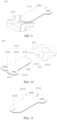
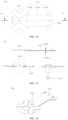
- the terminal connecting portion includes a plurality of terminal connecting sub-portions stacked in layers. Each terminal connecting sub-portion includes a riveting sub-portion. Any two adjacent riveting sub-portions are fixed together by riveting.
- any two adjacent terminal connecting sub-portions are fixed together by riveting by two adjacent riveting sub-portions, thereby implementing a rivet connection.
- the rivet connection improves the positioning precision during connection of the terminal connecting portion, and avoids the welding process, thereby improving the production efficiency of the current collecting component.
- any two adjacent riveting sub-portions are welded to each other.
- each riveting position between the terminal connecting sub-portions is reinforced by welding.
- the welding reinforcement increases the connection strength between the terminal connecting sub-portions.
- the welding reinforcement increases the flow area of the current collecting component, reduces the internal resistance, reduces the temperature rise, and improves the safety performance of the battery cell.
- the terminal connecting portion is provided with a fixing structure.
- the fixing structure all the riveting sub-portions are stacked in sequence and mated to each other.
- the riveting sub-portions of the terminal connecting sub-portions on adjacent layers are stacked to form a fixing structure, so as to be positioned accurately and easy to align. In addition, no welding process is required, thereby improving the production efficiency of the current collecting component.
- the riveting of the riveting sub-portions of the terminal connecting sub-portions on adjacent layers can reduce burrs.
- the fixing structure is disposed at an end region, close to the electrode terminal, of the terminal connecting portion. In this way, all the terminal connecting sub-portions can be riveted together to form a one-piece terminal connecting portion.
- the fixing structure is disposed at an end region, close to the tab connecting portion, of the terminal connecting portion. In this way, after all the terminal connecting sub-portions are riveted together to form a one-piece terminal connecting portion, the one-piece terminal connecting portion can be conveniently riveted to the tab connecting portion.
- the fixing structure is disposed at an end region, close to the electrode terminal, of the terminal connecting portion, and at an end region, close to the tab connecting portion, of the terminal connecting portion.
- all the terminal connecting sub-portions can be riveted together to form a one-piece terminal connecting portion.
- the one-piece terminal connecting portion can be conveniently riveted to the tab connecting portion.
- a fixing structure is disposed on both opposite ends of the terminal connecting portion, so that the bonding force of the two ends of the one-piece terminal connecting portion is relatively uniform, and the bonding is firmer on the whole.
- the number of the fixing structures is one or more.
- the number of the fixing structures is one, a high positioning precision is ensured during riveting of the terminal connecting sub-portions on any adjacent layers.
- the plurality of fixing structures not only ensures a high positioning precision during riveting of the terminal connecting sub-portions on any adjacent layers, but also improves the connection strength between the terminal connecting sub-portions, thereby preventing easy detachment from each other, and improving the operating stability of the current collecting component.
- a cross-sectional shape of the fixing structure is any one of, but is not limited to, a square, a rectangle, or a circle.
- the cross-sectional shape of the fixing structure is not limited, and may be any one of a square, a rectangle, or a circle, thereby reducing the design difficulty of the terminal connecting portion, and simplifying the manufacture of the current collecting component.
- the terminal connecting portion includes a first main surface and a second main surface arranged opposite to each other along a thickness direction of the terminal connecting portion after being spread out.
- the fixing structure forms a recessed portion on a side at which the first main surface is located, and the fixing structure forms a first protruding portion on the second main surface.
- the fixing structure includes a first protruding portion and a recessed portion, so that misalignment between layers can be avoided during stacking when the terminal connecting portion is formed by riveting, so as to implement accurate positioning and easy alignment. In addition, no welding process is required, thereby improving the production efficiency of the current collecting component.
- the fixing structure includes a first protruding portion and a recessed portion, thereby reducing burrs.
- the tab connecting portion is disposed on one side, close to the second main surface, of the terminal connecting portion.
- the tab connecting portion is provided with a first accommodation portion, and the first protruding portion is accommodated in the first accommodation portion.
- the first protruding portion is accommodated in the first accommodation portion, and can play a positioning role when the terminal connecting portion is connected to the tab connecting portion.
- the terminal connecting portion is fixedly connected to the tab connecting portion by the first protruding portion.
- the first protruding portion is fixedly connected to the first accommodation portion, so that the terminal connecting portion is fixedly connected to the tab connecting portion by the first protruding portion.
- the design in this application improves the positioning precision when the terminal connecting portion is connected to the tab connecting portion, and avoids the welding process, thereby improving the production efficiency of the current collecting component.
- each riveting sub-portion includes a sub-protrusion and a sub-recess.
- Each sub-protrusion protrudes toward the second main surface.
- Each sub-recess is recessed from the first main surface toward the second main surface.
- the sub-protrusion of one riveting sub-portion among two adjacent riveting sub-portions is accommodated in and fixedly connected to the sub-recess of the other riveting sub-portion.
- the sub-protrusion of one of two adjacent terminal connecting sub-portions is riveted to the sub-recess of the other terminal connecting sub-portion, thereby avoiding misalignment between layers during stacking, implementing accurate positioning and easy alignment.
- no welding process is required, thereby improving the production efficiency of the current collecting component.
- the riveting between the sub-protrusion of one of two adjacent terminal connecting sub-portions and the sub-recess of the other terminal connecting sub-portion can reduce burrs.
- bending the plurality of terminal connecting sub-portions to a greater extent can also reduce the space occupied by the current collecting component in the height direction, increase the energy density of the battery cell, and in turn, increase the energy density of the battery, and improve the runtime of the electrical device.
- the term "and/or” merely indicates a relationship between related items, and represents three possible relationships.
- “A and/or B” may represent the following three circumstances: A alone, both A and B, and B alone.
- the character “/” herein generally indicates an "or” relationship between the item preceding the character and the item following the character.
- a direction or a positional relationship indicated by the terms such as “center”, “longitudinal”, “transverse”, “length”, “width”, “thickness”, “up”, “down”, “before”, “after”, “left”, “right”, “vertical”, “horizontal”, “top”, “bottom”, “in”, “out”, “clockwise”, “counterclockwise”, “axial”, “radial”, and “circumferential” is a direction or positional relationship based on the illustration in the drawings, and is merely intended for ease or brevity of description of embodiments of this application, but not intended to indicate or imply that the indicated device or component is necessarily located in the specified direction or constructed or operated in the specified direction. Therefore, such terms are not to be understood as a limitation on embodiments of this application.
- Power batteries are not only used in energy storage power systems such as hydro, thermal, wind, and solar power stations, but also widely used in electric means of transport such as electric bicycles, electric motorcycles, and electric vehicles, and used in many other fields such as military equipment and aerospace.
- the market demand for power batteries keeps soaring with the expansion of the application fields of the power batteries.
- a tab of an electrode assembly is flattened, a current collecting component and the tab are welded together, and the current collecting component is bent and electrically connected to an electrode terminal to output electrical current.
- a terminal connecting portion of the current collecting component needs to avoid being excessively thick. Therefore, the flow area S of the terminal connecting portion is very small.
- the bending process requires the terminal connecting portion to be bent three times.
- the inventor hereof has found through research that the terminal connecting portion of the current collecting component can be designed as a plurality of terminal connecting sub-portions stacked in layers.
- the bonding force between different layers of terminal connecting sub-portions is relatively small, and deformation is more tolerable between layers in a case of bending. In this way, the bendability of the plurality of terminal connecting sub-portions is higher. With the same bendability, the overall thickness of the multilayered terminal connecting portion can be made larger. The flow area of the current collecting component is increased, the internal resistance is reduced, the temperature rise is reduced, and therefore, the safety of the battery is improved.
- the inventor hereof in order to design the terminal connecting portion of the current collecting component into a plurality of terminal connecting sub-portions stacked in layers, the inventor hereof also finds that: the multilayered terminal connecting portion obtained by stacking a material in a plurality of layers and then cutting the stacked layers gives rise to a large number of edge burrs, and, if a plurality of single-layer terminal connecting sub-portions are punched out and then stacked up and welded to obtain a multilayered terminal connecting portion, the sub-portions are unable to be well aligned, and the welding efficiency is relatively low. Neither of the production methods can implement mass production. After in-depth research, the inventor hereof has designed a current collecting component for use in a battery cell.
- the terminal connecting portion of the current collecting component is designed as a plurality of terminal connecting sub-portions stacked in layers.
- the terminal connecting sub-portions on any two adjacent layers are riveted to each other, thereby avoiding generation of burrs, achieving a high positioning precision, and enabling easy alignment.
- no welding process is involved, thereby improving the production efficiency of the terminal connecting portion and facilitating mass production.
- the battery cell disclosed in an embodiment of this application is applicable to an electrical device that uses a battery as a power supply and is applicable to various energy storage systems that use a battery as an energy storage unit.
- the electrical devices may be, but are not limited to, a mobile phone, a tablet, a notebook computer, an electric toy, an electric tool, an electric power cart, an electric vehicle, a ship, a spacecraft, or the like.
- the electric toy may include stationary or mobile electric toys, such as game console, electric car toy, electric ship toy, electric airplane toy, and the like.
- the spacecraft may include airplane, rocket, space shuttle, spaceship, and the like.
- a vehicle 1000 is used as an example of the electrical device according to an embodiment of this application.
- FIG. 1 is a schematic structural diagram of a vehicle 1000 according to some embodiments of this application.
- the vehicle 1000 may be an oil-fueled vehicle, a natural gas vehicle, or a new energy vehicle.
- the new energy vehicle may be a battery electric vehicle, a hybrid electric vehicle, a range-extended electric vehicle, or the like.
- a battery 100 is disposed inside the vehicle 1000.
- the battery 100 may be disposed at the bottom, front, or rear of the vehicle 1000.
- the battery 100 may be configured to supply power to the vehicle 1000.
- the battery 100 may serve as an operating power supply of the vehicle 1000.
- the vehicle 1000 may further include a controller 200 and a motor 300.
- the controller 200 is configured to control the battery 100 to supply power to the motor 300, for example, to meet electrical energy requirements in starting, navigating, or running the vehicle 1000.
- the battery 100 serves not only as an operating power supply of the vehicle 1000, but may also serve as a driving power supply of the vehicle 1000 to provide driving power for the vehicle 1000 in place of or partly in place of fuel oil or natural gas.
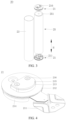
- the shell 23 may be a cylindrical structure. An accommodation cavity is formed inside the shell 23, and is configured to accommodate the electrode assembly 25 and an electrolyte solution. The shell 23 is provided with openings at both ends so that the electrode assembly 25 can be placed into the accommodation cavity of the shell 23 through the openings.
- the shell 23 may be made of a metal material such as aluminum or aluminum alloy, or may be made of an insulation material such as plastic or rubber.
Landscapes
- Chemical & Material Sciences (AREA)
- Chemical Kinetics & Catalysis (AREA)
- Electrochemistry (AREA)
- General Chemical & Material Sciences (AREA)
- Engineering & Computer Science (AREA)
- Manufacturing & Machinery (AREA)
- Connection Of Batteries Or Terminals (AREA)
Applications Claiming Priority (1)
| Application Number | Priority Date | Filing Date | Title |
|---|---|---|---|
| PCT/CN2023/074140 WO2024159455A1 (zh) | 2023-02-01 | 2023-02-01 | 电池单体、电池及用电装置 |
Publications (2)
| Publication Number | Publication Date |
|---|---|
| EP4579924A1 true EP4579924A1 (de) | 2025-07-02 |
| EP4579924A4 EP4579924A4 (de) | 2026-01-28 |
Family
ID=92145586
Family Applications (1)
| Application Number | Title | Priority Date | Filing Date |
|---|---|---|---|
| EP23919033.3A Pending EP4579924A4 (de) | 2023-02-01 | 2023-02-01 | Batteriezelle, batterie und elektrische vorrichtung |
Country Status (4)
| Country | Link |
|---|---|
| US (1) | US20250233285A1 (de) |
| EP (1) | EP4579924A4 (de) |
| CN (1) | CN120322902A (de) |
| WO (1) | WO2024159455A1 (de) |
Families Citing this family (1)
| Publication number | Priority date | Publication date | Assignee | Title |
|---|---|---|---|---|
| CN119009618A (zh) * | 2024-10-10 | 2024-11-22 | 福建龙净储能电池有限公司 | 转接片成型工艺、电池组装工艺及单体电池 |
Family Cites Families (9)
| Publication number | Priority date | Publication date | Assignee | Title |
|---|---|---|---|---|
| CN102903881B (zh) * | 2011-07-29 | 2016-02-03 | 比亚迪股份有限公司 | 一种用于电池模块之间的连接件及电池系统 |
| JP2017199652A (ja) * | 2016-04-25 | 2017-11-02 | 株式会社Gsユアサ | 蓄電素子 |
| CN205666257U (zh) * | 2016-05-27 | 2016-10-26 | 杜福宙 | 一种极柱铆接软连接片的锂离子电池盖板 |
| CN115836438B (zh) * | 2021-01-29 | 2024-10-01 | 宁德时代新能源科技股份有限公司 | 电池单体、电池、用电设备、电池单体的制造方法及设备 |
| CN112821011A (zh) * | 2021-02-24 | 2021-05-18 | 东莞市骅新电子科技有限公司 | 一种新能源电池搭接焊软连接片的生产工艺及其制品 |
| CN216085104U (zh) * | 2021-10-19 | 2022-03-18 | 宁德时代新能源科技股份有限公司 | 电池单体、电池及用电装置 |
| CN218299828U (zh) * | 2022-07-21 | 2023-01-13 | 厦门海辰储能科技股份有限公司 | 集流体、端盖组件、电池及电池包 |
| CN218300152U (zh) * | 2022-07-21 | 2023-01-13 | 厦门海辰储能科技股份有限公司 | 集流体、端盖组件、电池及电池包 |
| CN115425365B (zh) * | 2022-09-29 | 2023-09-26 | 厦门海辰储能科技股份有限公司 | 集流组件、电池、电池包及用电设备 |
-
2023
- 2023-02-01 EP EP23919033.3A patent/EP4579924A4/de active Pending
- 2023-02-01 WO PCT/CN2023/074140 patent/WO2024159455A1/zh not_active Ceased
- 2023-02-01 CN CN202380083589.3A patent/CN120322902A/zh active Pending
-
2025
- 2025-04-03 US US19/169,716 patent/US20250233285A1/en active Pending
Also Published As
| Publication number | Publication date |
|---|---|
| WO2024159455A1 (zh) | 2024-08-08 |
| US20250233285A1 (en) | 2025-07-17 |
| EP4579924A4 (de) | 2026-01-28 |
| CN120322902A (zh) | 2025-07-15 |
Similar Documents
| Publication | Publication Date | Title |
|---|---|---|
| KR102865896B1 (ko) | 배터리 셀, 배터리 및 전기 설비 | |
| CN219591599U (zh) | 电池单体、电池及用电装置 | |
| EP4068490B1 (de) | Batteriezelle, batterie, elektrische vorrichtung, herstellungsverfahren und vorrichtung für eine batteriezelle | |
| EP4498488A1 (de) | Endkappe, batteriezelle, batterie und elektrische vorrichtung | |
| CN220628150U (zh) | 一种圆柱电芯、电池组及电子设备 | |
| US20240047836A1 (en) | Battery cell, battery, electrical device, and device and method for manufacturing battery cell | |
| US20240380039A1 (en) | Battery top cover, top cover assembly, battery cell, battery, and power consuming device | |
| CN220290875U (zh) | 电池单体、电池和用电装置 | |
| US20250233285A1 (en) | Battery cell, battery, and electrical device | |
| US20250379335A1 (en) | Battery cell, battery, and electrical device | |
| US20230275296A1 (en) | Battery, power consumption device, and method and device for producing battery | |
| EP3926751B1 (de) | Sekundärbatterie mit spezifischem stromabnehmerelement, batteriemodul und vorrichtung | |
| KR20250029170A (ko) | 배터리셀, 배터리 및 전기기기 | |
| EP4395013A1 (de) | Batterie, stromverbrauchende vorrichtung, verfahren zur herstellung der batterie und vorrichtung zur herstellung der batterie | |
| US20250070403A1 (en) | Battery cell, battery, electrical apparatus, and method for manufacturing battery cell | |
| CN118763365B (zh) | 电池单体、制备方法、制造设备、电池装置及用电装置 | |
| CN220290877U (zh) | 电池单体、电池和用电装置 | |
| CN220553562U (zh) | 圆柱电芯、电池组及电子设备 | |
| CN219203426U (zh) | 电池及用电设备 | |
| EP4109666A1 (de) | Batteriezelle, herstellungsverfahren und herstellungssystem dafür, batterie und elektrisches gerät | |
| EP4254610A1 (de) | Batterie, elektrische vorrichtung, verfahren zur herstellung einer batteriezelle und vorrichtung | |
| CN221239714U (zh) | 二次电池、电池组及电子设备 | |
| CN222927640U (zh) | 电池单体、电池、储能装置和用电装置 | |
| EP4498502A1 (de) | Endkappe, batteriezelle, batterie und elektrische vorrichtung | |
| CN119833768B (zh) | 支撑装置、焊接设备、电池单体、电池装置和用电装置 |
Legal Events
| Date | Code | Title | Description |
|---|---|---|---|
| STAA | Information on the status of an ep patent application or granted ep patent |
Free format text: STATUS: THE INTERNATIONAL PUBLICATION HAS BEEN MADE |
|
| PUAI | Public reference made under article 153(3) epc to a published international application that has entered the european phase |
Free format text: ORIGINAL CODE: 0009012 |
|
| STAA | Information on the status of an ep patent application or granted ep patent |
Free format text: STATUS: REQUEST FOR EXAMINATION WAS MADE |
|
| 17P | Request for examination filed |
Effective date: 20250327 |
|
| AK | Designated contracting states |
Kind code of ref document: A1 Designated state(s): AL AT BE BG CH CY CZ DE DK EE ES FI FR GB GR HR HU IE IS IT LI LT LU LV MC ME MK MT NL NO PL PT RO RS SE SI SK SM TR |
|
| A4 | Supplementary search report drawn up and despatched |
Effective date: 20260108 |
|
| RIC1 | Information provided on ipc code assigned before grant |
Ipc: H01M 50/502 20210101AFI20251223BHEP Ipc: H01M 50/152 20210101ALI20251223BHEP Ipc: H01M 50/107 20210101ALI20251223BHEP Ipc: H01M 50/179 20210101ALI20251223BHEP Ipc: H01M 50/533 20210101ALI20251223BHEP Ipc: H01M 50/538 20210101ALI20251223BHEP Ipc: H01M 50/559 20210101ALI20251223BHEP Ipc: H01M 50/566 20210101ALI20251223BHEP Ipc: H01M 50/567 20210101ALI20251223BHEP |