EP4579992A1 - Systèmes, procédés et appareil pour détecter la fin de vie d'une batterie - Google Patents
Systèmes, procédés et appareil pour détecter la fin de vie d'une batterie Download PDFInfo
- Publication number
- EP4579992A1 EP4579992A1 EP24222326.1A EP24222326A EP4579992A1 EP 4579992 A1 EP4579992 A1 EP 4579992A1 EP 24222326 A EP24222326 A EP 24222326A EP 4579992 A1 EP4579992 A1 EP 4579992A1
- Authority
- EP
- European Patent Office
- Prior art keywords
- battery unit
- threshold
- satisfies
- asoc
- medical device
- Prior art date
- Legal status (The legal status is an assumption and is not a legal conclusion. Google has not performed a legal analysis and makes no representation as to the accuracy of the status listed.)
- Pending
Links
Images


Classifications
-
- A—HUMAN NECESSITIES
- A61—MEDICAL OR VETERINARY SCIENCE; HYGIENE
- A61N—ELECTROTHERAPY; MAGNETOTHERAPY; RADIATION THERAPY; ULTRASOUND THERAPY
- A61N1/00—Electrotherapy; Circuits therefor
- A61N1/18—Applying electric currents by contact electrodes
- A61N1/32—Applying electric currents by contact electrodes alternating or intermittent currents
- A61N1/36—Applying electric currents by contact electrodes alternating or intermittent currents for stimulation
- A61N1/362—Heart stimulators
- A61N1/37—Monitoring; Protecting
-
- H—ELECTRICITY
- H02—GENERATION; CONVERSION OR DISTRIBUTION OF ELECTRIC POWER
- H02J—ELECTRIC POWER NETWORKS; CIRCUIT ARRANGEMENTS OR SYSTEMS FOR SUPPLYING OR DISTRIBUTING ELECTRIC POWER; SYSTEMS FOR STORING ELECTRIC ENERGY
- H02J7/00—Circuit arrangements for charging or discharging batteries or for supplying loads from batteries
- H02J7/80—Circuit arrangements for charging or discharging batteries or for supplying loads from batteries including monitoring or indicating arrangements
- H02J7/82—Control of state of charge [SOC]
-
- A—HUMAN NECESSITIES
- A61—MEDICAL OR VETERINARY SCIENCE; HYGIENE
- A61N—ELECTROTHERAPY; MAGNETOTHERAPY; RADIATION THERAPY; ULTRASOUND THERAPY
- A61N1/00—Electrotherapy; Circuits therefor
- A61N1/18—Applying electric currents by contact electrodes
- A61N1/32—Applying electric currents by contact electrodes alternating or intermittent currents
- A61N1/38—Applying electric currents by contact electrodes alternating or intermittent currents for producing shock effects
- A61N1/39—Heart defibrillators
- A61N1/3904—External heart defibrillators [EHD]
-
- A—HUMAN NECESSITIES
- A61—MEDICAL OR VETERINARY SCIENCE; HYGIENE
- A61N—ELECTROTHERAPY; MAGNETOTHERAPY; RADIATION THERAPY; ULTRASOUND THERAPY
- A61N1/00—Electrotherapy; Circuits therefor
- A61N1/18—Applying electric currents by contact electrodes
- A61N1/32—Applying electric currents by contact electrodes alternating or intermittent currents
- A61N1/38—Applying electric currents by contact electrodes alternating or intermittent currents for producing shock effects
- A61N1/39—Heart defibrillators
- A61N1/3975—Power supply
-
- G—PHYSICS
- G01—MEASURING; TESTING
- G01R—MEASURING ELECTRIC VARIABLES; MEASURING MAGNETIC VARIABLES
- G01R31/00—Arrangements for testing electric properties; Arrangements for locating electric faults; Arrangements for electrical testing characterised by what is being tested not provided for elsewhere
- G01R31/36—Arrangements for testing, measuring or monitoring the electrical condition of accumulators or electric batteries, e.g. capacity or state of charge [SoC]
- G01R31/371—Arrangements for testing, measuring or monitoring the electrical condition of accumulators or electric batteries, e.g. capacity or state of charge [SoC] with remote indication, e.g. on external chargers
-
- G—PHYSICS
- G01—MEASURING; TESTING
- G01R—MEASURING ELECTRIC VARIABLES; MEASURING MAGNETIC VARIABLES
- G01R31/00—Arrangements for testing electric properties; Arrangements for locating electric faults; Arrangements for electrical testing characterised by what is being tested not provided for elsewhere
- G01R31/36—Arrangements for testing, measuring or monitoring the electrical condition of accumulators or electric batteries, e.g. capacity or state of charge [SoC]
- G01R31/382—Arrangements for monitoring battery or accumulator variables, e.g. SoC
-
- G—PHYSICS
- G01—MEASURING; TESTING
- G01R—MEASURING ELECTRIC VARIABLES; MEASURING MAGNETIC VARIABLES
- G01R31/00—Arrangements for testing electric properties; Arrangements for locating electric faults; Arrangements for electrical testing characterised by what is being tested not provided for elsewhere
- G01R31/36—Arrangements for testing, measuring or monitoring the electrical condition of accumulators or electric batteries, e.g. capacity or state of charge [SoC]
- G01R31/392—Determining battery ageing or deterioration, e.g. state of health
-
- H—ELECTRICITY
- H01—ELECTRIC ELEMENTS
- H01M—PROCESSES OR MEANS, e.g. BATTERIES, FOR THE DIRECT CONVERSION OF CHEMICAL ENERGY INTO ELECTRICAL ENERGY
- H01M10/00—Secondary cells; Manufacture thereof
- H01M10/42—Methods or arrangements for servicing or maintenance of secondary cells or secondary half-cells
- H01M10/48—Accumulators combined with arrangements for measuring, testing or indicating the condition of cells, e.g. the level or density of the electrolyte
- H01M10/486—Accumulators combined with arrangements for measuring, testing or indicating the condition of cells, e.g. the level or density of the electrolyte for measuring temperature
-
- H—ELECTRICITY
- H02—GENERATION; CONVERSION OR DISTRIBUTION OF ELECTRIC POWER
- H02J—ELECTRIC POWER NETWORKS; CIRCUIT ARRANGEMENTS OR SYSTEMS FOR SUPPLYING OR DISTRIBUTING ELECTRIC POWER; SYSTEMS FOR STORING ELECTRIC ENERGY
- H02J7/00—Circuit arrangements for charging or discharging batteries or for supplying loads from batteries
- H02J7/80—Circuit arrangements for charging or discharging batteries or for supplying loads from batteries including monitoring or indicating arrangements
- H02J7/84—Control of state of health [SOH]
-
- G—PHYSICS
- G01—MEASURING; TESTING
- G01R—MEASURING ELECTRIC VARIABLES; MEASURING MAGNETIC VARIABLES
- G01R31/00—Arrangements for testing electric properties; Arrangements for locating electric faults; Arrangements for electrical testing characterised by what is being tested not provided for elsewhere
- G01R31/36—Arrangements for testing, measuring or monitoring the electrical condition of accumulators or electric batteries, e.g. capacity or state of charge [SoC]
- G01R31/3644—Constructional arrangements
- G01R31/3647—Constructional arrangements for determining the ability of a battery to perform a critical function, e.g. cranking
-
- H—ELECTRICITY
- H02—GENERATION; CONVERSION OR DISTRIBUTION OF ELECTRIC POWER
- H02J—ELECTRIC POWER NETWORKS; CIRCUIT ARRANGEMENTS OR SYSTEMS FOR SUPPLYING OR DISTRIBUTING ELECTRIC POWER; SYSTEMS FOR STORING ELECTRIC ENERGY
- H02J2105/00—Networks for supplying or distributing electric power characterised by their spatial reach or by the load
- H02J2105/40—Networks for supplying or distributing electric power characterised by their spatial reach or by the load characterised by the loads connecting to the networks or being supplied by the networks
- H02J2105/46—Medical devices, medical implants or life supporting devices
Definitions
- the present disclosure relates generally to medical devices and, more particularly, to systems and methods for detecting the end of the life of a battery powering an electronic device, such as a portable medical device.
- Examples of medical devices where monitoring battery health is important include portable external defibrillators.
- external defibrillators There are several types of external defibrillators, including manual defibrillators, which are generally used by medical personnel, and automated external defibrillators, commonly known by the acronym AED, which are designed for use by laypersons.
- AED automated external defibrillators
- An AED is typically a small, portable device that analyzes the heart's rhythm and if the analysis determines that a defibrillating shock is advisable, either prompts the user to deliver a defibrillation shock or delivers a defibrillation shock without user interaction. Once a typical AED is activated, it can guide the user through each step of the defibrillation process by providing instructions in the form of aural or visual prompts.
- AED's may analyze the patient's heart rhythm and charge an energy storage device before a defibrillating shock can be delivered to a person or patient experiencing a medical condition, such as a cardiac arrest. This is done using a decision-making algorithm commonly referred to as a shock advisory algorithm.
- Current commercially available defibrillators may analyze an electrocardiogram (ECG) to determine if the person's heart is in a condition where delivery of a defibrillating shock is advisable, and after this analysis is done, charge if a shock is recommended.
- ECG electrocardiogram
- the defibrillation shock provided by portable external defibrillators is a high-energy defibrillation pulse to the chest of a person to cause the person's heart to stop fibrillating and return to a normal rhythm. Sometimes the application of a single defibrillation pulse fails to restore the person's heart to a normal rhythm. In such an event, it may be necessary to apply additional defibrillation pulses. Further, portable external cardiac defibrillators are typically required to perform a range of monitoring tasks, including conducting ECG testing and monitoring compression and ventilations during cardiopulmonary resuscitation (CPR) treatment.
- CPR cardiopulmonary resuscitation
- Portable external cardiac defibrillators are typically used by first responders or laypersons in the field, where alternative energy sources for powering the devices or recharging batteries may not readily available.
- Portable external cardiac defibrillators generally use a battery pack or unit to power the defibrillator.
- the battery pack may allow an energy storage device (e.g., a capacitor) to be charged in order to generate a defibrillation pulse. This operation can require drawing a high level of power from the battery pack over a short period of time.
- the defibrillator may not be able to be used to treat a person experiencing a cardiac arrest and the battery pack may need to be recharged or replaced.
- it is beneficial to monitor the battery health of the defibrillator and alert the user of the defibrillator before the battery pack is depleted or is at its end of life.
- the present application is directed to embodiments relating to systems, methods, and apparatus for battery monitoring and/or management of a device, such as a medical device.
- the embodiments may be configured to monitor conditions and parameters of one or more battery units of the device.
- the conditions and parameters of the battery units may be evaluated to detect the end of life of one or more of the battery units.
- the embodiments may monitor battery voltages, charging cycles, absolute state of charges (ASOC), battery currents, charging currents, charging voltages, discharge cycles, dates of battery first use, battery manufacturing dates, charge capacities, battery temperatures, and/or combinations thereof.
- the embodiments may provide an indication that one or more of the battery units is nearing or at the end of life. Further, the embodiments may select one or more of the battery units to provide power and/or may adjust the charging rate of an energy storage device based on the conditions and parameters of the one or more battery units of the device.
- a portable medical device may comprise a display, a defibrillator port, a battery unit, and a processor.
- the processor may be configured to determine a cycle count of the battery unit. The cycle count represents a number of times the battery unit has been charged.
- the processor may also be configured to determine whether the cycle count satisfies a cycle count threshold and/or other battery condition thresholds are met. Further, the processor may be configured to, in response to determining that the cycle count satisfies the cycle count threshold, cause one or more graphical elements to be displayed on the display.
- a method for monitoring a battery unit of a medical device may comprise determining a cycle count of the battery unit and/or other battery conditions. The method may also comprise determining whether the cycle count satisfies a cycle count threshold and/or other battery condition thresholds are met. Further, the method may comprise causing one or more graphical elements to be displayed in response to determining that the cycle count and/or other battery conditions satisfy a threshold.
- a non-transitory computer-readable medium storing instructions that, when the instructions are executed by one or more processors, causes the one or more processors to perform operations for monitoring a battery unit of a medical device.
- the operations may comprise determining a cycle count of a battery unit of a medical device and/or other battery conditions.
- the operations may also comprise determining whether the cycle count satisfies a cycle count threshold and/or other battery condition thresholds are met.
- the operations may comprise causing one or more graphical elements to be displayed in response to determining that the cycle count and/or other battery conditions satisfy a threshold.
- a portable medical device may comprise a defibrillator port, a battery unit, a charging circuit, an energy storage device, and a processor.
- the processor may be configured to determine a temperature and an absolute state of charge (ASOC) of a battery unit.
- the processor may also be configured to determine whether the temperature of the battery unit satisfies a temperature threshold and determine whether the ASOC of the battery unit satisfies a ASOC threshold. Further, the processor may also be configured to, in response to determining that the temperature satisfies the temperature threshold and the ASOC satisfies the ASOC threshold, cause a charging circuit to charge an energy storage device at a first charging rate.
- ASOC absolute state of charge
- a method for charging an energy storage device of a portable medical device may comprise charging the energy storage device of the portable medical device at a first charging rate and determining a temperature and an absolute state of charge (ASOC) of the battery unit.
- the method may also be comprises determining whether the temperature of the battery unit satisfies a temperature threshold and determining whether the ASOC of the battery unit satisfies an ASOC threshold.
- the method may also comprise, in response to determining that the temperature satisfies the temperature threshold and the ASOC satisfies the ASOC threshold, cause the charging circuit to charge the energy storage device at a second charging rate.
- a portable medical device may comprise a defibrillator port, a battery unit, a charging circuit, an energy storage device, and a processor.
- the processor may be configured to determine a voltage level of the battery unit during charging of the energy storage device.
- the processor may also be configured determine whether the voltage level of the battery unit satisfies a voltage threshold. Further, the processor may also be configured to, in response to determining that the voltage level satisfies the voltage threshold, cause the charging circuit to charge the energy storage device at a second charging rate.
- a method for charging an energy storage device of a portable medical device may comprise charging the energy storage device at a first charging rate.
- the method may also comprise determining a voltage level of a battery unit of the portable medical device during charging the energy storage device and determining whether the voltage level of a battery unit satisfies a voltage level threshold. Further, the method may also comprise, in response to determining that the voltage level satisfies the voltage level threshold, adjusting the first charging rate to a second charging rate.
- the distinguishing letter "A" may be used.
- the reference number 118 may be used without a distinguishing letter.
- an ordinal term e.g., "first,” “second,” “third,” etc.
- an element such as a structure, a component, an operation, etc.
- the term “set” refers to a grouping of one or more elements
- the term “plurality” refers to multiple elements.
- the present application is directed to embodiments relating to systems, methods, and apparatus for battery monitoring and/or management of a device, such as a medical device.
- the embodiments may be configured to monitor conditions or parameters of one or more battery units of the device.
- the conditions and parameters of the battery units may be evaluated to detect an end of life condition of the one or more battery units.
- the embodiments may monitor battery voltages, charging cycle, absolute state of charges (ASOC), battery currents, charging currents, charging voltages, discharge cycles, dates of battery first use, battery manufacturing dates, charge capacities, battery temperatures, and/or combinations thereof.
- the embodiments may provide an indication to a user that one or more of the battery units is nearing or at the end of life. Further, the embodiments may select one or more of the battery units to provide power and/or may adjust the charging rate of an energy storage device based on the conditions and parameters of the one or more battery units.
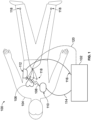
- Figure 1 is a diagram of a representation of an exemplary scene 100 showing use of a medical device 102 for monitoring and providing treatment or therapy to a person 104 experiencing a medical condition, such as a cardiac arrest.
- the medical device 102 may be operated by a user (e.g., a healthcare professional, service worker, a doctor, a first responder, etc.) and may be used in a hospital or a pre-hospital environment or setting.
- the medical device 102 may include functions and operations of an external defibrillator, such as a manual defibrillator, an automatic external defibrillator (AED), or any other suitable defibrillator.
- the medical device 102 may be a monitor defibrillator, which is a combination of a monitor and a defibrillator.
- the medical device 102 is positioned near the person 104 (e.g. patient).
- the person 104 may be experiencing a condition in his or her heart 106, which could be, for example, cardiac arrest or any other cardiac rhythm abnormality.
- the person 104 may be lying on his or her back on a surface, such as the ground or a bed, and may be located in a hospital, a home, or a pre-hospital environment (e.g., an ambulance).
- the medical device 102 may be configured to generate an electrical pulse 108 and deliver the electrical pulse 108 to the person 104.
- the electrical pulse 108 also known as a defibrillation shock or therapy shock, is intended to go through and restart the heart 106, in an effort to save the life of the person 104.
- the electrical pulse 108 can further include one or more pacing pulses and the like.
- the electrical pulse 108 may be delivered to the person 104 using defibrillation electrodes 110 and 112.
- the defibrillation electrodes 110 and 112 may include hand-held electrode paddles or electrode pads placed on the body of the person 104.
- An electrical cable 114 may connect the defibrillation electrode 110 to the medical device 102 and an electrical cable 116 may connection the defibrillation electrode 112 to the medical device 102.
- the medical device 102 may administer, via the defibrillation electrodes 110 and 112, the electric pulse 108 through the heart 106 of person 104.
- the defibrillation electrodes 110 and 112 may also be configured to sense or detect one or more conditions and/or physiological parameters of the person 104 and generate signals representative of the conditions and physiological parameters.
- one or more sensors or electrodes 118 may be placed at various locations on the body of the person 104.
- the sensors 118 may be configured to sense or detect conditions and/or physiological parameters of the person 104 and produce signals representative of the conditions and physiological parameters.
- An electrical cable 120 may connect the sensors 118 to the medical device 102.
- the physiological parameters generated by the sensors 118 and/or the defibrillation electrodes 110 and 112 may be provided to the medical device 102 for analysis.
- the physiological parameters may include ECG data, heart rhythm data, heart rate data, cardiac output data, blood flow data, a level of perfusion, respiration data, body temperature data, and/or any other suitable physiological parameter that may be used to assess the physical condition of the person 104.
- the medical device 102 may be configured to select an appropriate treatment protocol based on the physiological parameters. For example, the medical device 102 may determine a cardiopulmonary resuscitation (CPR) treatment to apply to the person 104. The medical device 102 may also determine whether a defibrillation pulse should be applied or delivered to the person 104. Further, the medical device 102 may display the representations of the conditions and/or physiological parameters of the person 104 to assist a user in treating and diagnosing medical conditions.
- CPR cardiopulmonary resuscitation
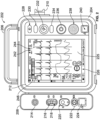
- FIG 2 illustrates a front view of a medical device 202, in accordance with an example implementation.
- the medical device 202 can comprise the medical device 102 of Figure 1 .
- the medical device 202 may be configured to monitor and provide treatment or care to a person or patient experiencing a medical condition, such as a cardiac arrest or any other cardiac rhythm abnormality.
- the medical device 202 may be operated by a user (e.g., a medical professional, a first responder, a healthcare professional, service worker, a doctor, etc.) and may be used in a hospital or a pre-hospital environment or setting.
- the medical device 202 may be a monitor defibrillator, which is a combination of a monitor and a defibrillator.
- the medical device 202 may be configured to deliver an electrical pulse or shock to a person experiencing a medical condition.
- the medical device 202 may be configured to operate or function in one or more defibrillation modes, such as a manual defibrillation mode, an AED mode, or any other suitable defibrillation mode.
- the medical device 202 may be selected to operate in an AED mode when the medical device 202 is intended to be used by first responders and/or people who are not trained in providing medical treatment using defibrillation.
- the medical device 202 may determine whether a defibrillation pulse or shock is needed and, if so, charge an energy storage device (e.g., a capacitor) of the medical device 202 to a predetermined energy level and instruct the user to administer the defibrillation shock.
- the medical device 202 may also be configured to operate in a manual defibrillation mode when the medical device 202 is intended to be used by persons who are trained in providing medical treatment using defibrillation (e.g., medical professionals, such as doctors, nurses, paramedics, emergency medical technicians, etc.).
- the medical device 202 can monitor and evaluate conditions and physiological parameters of a person being treated for a medical condition.
- the medical device 202 may receive or acquire signals or voltages from one or more electrodes or sensors placed at various locations on the body of the person.
- the electrodes may sense or detect the physiological parameters of the person and produce signals representative of the physiological parameters.
- the representations of the physiological parameters may be displayed by the medical device 202 to assist a user in treating and diagnosing medical conditions of the person.
- the input module 208 of the medical device 202 may be coupled to or integral with the housing 204.
- the input module 208 may enable the medical device 202 to receive vital signs and other physiological parameters (e.g., a heart rate (HR) and ECG data) of a person via sensors (e.g., the sensors 118 of Figure 1 ).
- the sensors may be placed on the body of a person to sense or detect signals generated by the body or heart of the person.
- the input module 208 may include one or more ports or receptacles to enable the sensors to be detachably coupled to the input module 208.
- the input module 208 can include a port 214 configured to be connected to an oxygen saturation (SpO2) sensor, a port 216 configured to be connected to a temperature sensor, a port 218 configured to be connected to a sensor for measuring invasive blood pressure (IP) via a catheter, a port 220 configured to be connected to a sensor for measuring partial pressure of carbon dioxide (CO2) in gases in the airway via capnography, and a port 222 configured to be connected to sensor for measuring a non-invasive blood pressure (NIBP).
- the input module 208 may also include a communication port 224, such as a Universal Serial Bus (USB) port, that can be used to connect to an input device (e.g., a mouse, a keyboard, etc.).
- the input module 208 may include other ports to enable any other suitable physiologic parameter of a person to be monitored and evaluated by the medical device 202.
- a cable assembly or therapy cable may enable the defibrillation electrodes to be coupled to the ports of the defibrillation interface 210.
- Each therapy cable may include a defibrillation electrode attached at one end and a connector attached to the other end.
- the connector may be configured to be coupled to or plugged into a port or receptacle of the defibrillation interface 210.
- the output devices may also include an audio system that provides audio signals to aurally communicate with the user voice prompts that deliver instructions or commands, monotonal, ascending, descending or quickening tones to indicate alerts or warnings, or any other suitable audio signals for communicating with the user of the medical device 202.
- the user interface 212 of the medical device 202 includes a power button 228 configured to turn the medical device on and off (e.g., "On-Off" button), a charge button 230 configured to cause the medical device 202 to build an electric charge to be applied to the person in a form of a defibrillation shock or pulse, a defibrillation shock button 232 configured to cause the medical device 202 to apply a defibrillation pulse or therapy shock to a person during a defibrillation episode, an analyze button 234 configured to cause the medical device 202 to analyze physiologic parameters of a person (e.g., ECG data) to facilitate determining the appropriate time to apply a defibrillation pulse or shock, and a speed dial button 236 configured to navigate through menus of on-screen software.
- a power button 228 configured to turn the medical device on and off (e.g., "On-Off" button)
- a charge button 230 configured to cause the medical device 202 to build an
- the user interface 212 may also include a speaker 238 to provide audio output and a USB output port 240 to facilitate connecting the medical device 202 to a device such as a printer.
- the user interface 212 may include any other suitable output device for providing outputs or input device for receiving inputs from a user.
- the GUI 226 may also be configured to visually present various measured or calculated parameters associated with the person indicating the physical status of the person (e.g., an ECG), and/or instructions and/or commands, including prompts to perform cardiopulmonary resuscitation (CPR) treatment or other treatment instructions, to the user. Further, the GUI 226 may include multiple visual user interface items that are selectable or "clickable" by the user including user-selectable icons, user-selectable on-screen buttons, menus, widgets, scroll bars, graphical objects, and other items for facilitating user interaction.
- CPR cardiopulmonary resuscitation
- the GUI 226 includes graphical representations of a first battery unit indicator 242 and a second battery unit indicator 244.
- the first battery unit indicator 242 and second battery unit indicator 244 may be configured to display a status of a first battery unit and a status of a second battery unit, respectively.
- the first and second battery unit indicators 242 and 244 may provide a charging level of the first and second battery units.
- the GUI 226 may also display messages and information about end of life conditions of the first battery unit and/or the second battery unit. As shown, the GUI 226 may indicate that the first battery unit should be removed from service.
- the GUI 226 may also provide additional information about the battery units of the medical device 202, such as battery charge levels (e.g., a remaining charge), manufacturing dates, serial numbers, etc. Further, the GUI 226 may provide audible alarms or warnings when a battery unit of the medical device 202 has reached its end of life and/or should be removed and replaced.
- battery charge levels e.g., a remaining charge
- manufacturing dates e.g., a remaining charge
- serial numbers e.g., etc.
- the GUI 226 may provide audible alarms or warnings when a battery unit of the medical device 202 has reached its end of life and/or should be removed and replaced.
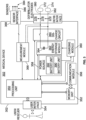
- FIG. 3 is a diagram showing components of a medical device 302, in accordance with an exemplary embodiment.
- the medical device 302 includes a processing unit 350, a memory unit 352, a user interface 354, a communication module or interface 356, a power source or module 358, a charging module 360, an energy storage module or device 362, a discharge circuit 364, a measurement module 366, a sensor interface 368, and a defibrillator interface 370.
- These components can be, for example, included in the medical devices of Figure 1 or 2 .
- the defibrillation interface 370 of the medical device 302 may be configured to enable an electrical pulse or shock to be delivered or applied to a person (e.g., a patient) experiencing a medical condition.
- the defibrillation interface 370 may comprise the defibrillation interface 210 of Figure 2 .
- the defibrillation interface 370 may include one or more ports or nodes 376 and 378 to enable the defibrillation electrodes 372 and 374 to be detachably coupled to the defibrillation interface 370.
- a cable assembly or therapy cable 380 may enable a defibrillation electrode (e.g., defibrillation electrode 372) to be coupled to the port 376 of the defibrillation interface 370 and a cable assembly or therapy cable 382 may enable a defibrillation electrode (e.g., defibrillation electrode 374) to be coupled to the port 378 of the defibrillation interface 370 of the medical device 302.
- the cable assemblies 380 and 382 may each include a connector configured to be coupled to or plugged into the ports 376 and 378 of the defibrillation interface 370.
- the connectors may be male or female connectors that are compatible with the ports 376 and 378 of the defibrillation interface 370 of the medical device 302.
- the defibrillation interface 370 may also enable the medical device 302 to receive physiological parameters (e.g., a heart rate (HR) and ECG data) of the person from the defibrillation electrodes 372 and 374.
- physiological parameters e.g., a heart rate (HR) and ECG data
- HR heart rate
- ECG data ECG data
- Each of the defibrillation electrodes 372 and 374 may be configured to measure one or more physiological parameters of the person (e.g., heart electrical activity, heart rate, etc.) and to provide signals representative of the physiological parameters to the defibrillation interface 370.
- an ECG signal of the person can be detected as a voltage difference between the defibrillation electrodes 372 and 374.
- the defibrillation electrodes 372 and 374 may also be used to determine device parameters indicative of a condition of the medical device, such as an electrode impedance or a user interaction with the medical device 302.
- the medical device 302 can detect an impedance between the defibrillation electrodes 372 and 374 to determine whether the defibrillation electrodes 372 and 374 are making sufficient electrical contact with a person's body.
- the sensor interface 368 of the medical device 302 may also be configured to receive physiological parameters (e.g., a heart rate (HR), ECG data, etc.) from one or more sensors 384 (e.g., physiological sensors).
- physiological parameters e.g., a heart rate (HR), ECG data, etc.
- the sensors 384 may be placed in contact with the body of a person being monitored or treated for a medical condition.
- Each of the sensors 384 may include a transducer configured to sense a signal or voltage of the person.
- the sensors 384 may measure or detect heart electrical activity, such as an electrocardiogram (ECG), saturation of the hemoglobin in arterial blood with oxygen (SpO2), carbon monoxide (carboxyhemoglobin, COHb) and/or methemoglobin (SpMet), partial pressure of carbon dioxide (CO2) in gases in the airway by means of capnography, total air pressure in the airway, flow rate or volume of air moving in and out of the airway, blood flow, blood pressure (e.g., non-invasive blood pressure (NIBP)), core body temperature with a temperature probe in the esophagus, oxygenation of hemoglobin within a volume of tissue (rSO2), and any other physiological parameters of a person being monitored or treated.
- ECG electrocardiogram
- SpO2 saturation of the hemoglobin in arterial blood with oxygen
- COHb carbon monoxide
- SpMet methemoglobin
- CO2 carbon dioxide
- NIBP non-invasive blood pressure
- rSO2 oxygenation of hemoglobin within
- the sensor interface 368 may include one or more receptacles or ports (e.g., an ECG port) to enable the sensors 384 to be detachably coupled to the medical device 302.
- the sensors 384 may be attached to the sensor interface 368 by cable assembles or therapy cables 386.
- the sensors 384 may be fixedly connected to the sensor interface 368.
- the therapy cables 386 may each include a sensor 384 at one end and to a connector at the opposite end. The connector can be configured to be coupled to or plugged into a port or receptacle of the sensor interface 368.
- the measurement module 366 of the medical device 302 may be configured to receive signals or sensor data from the sensor interface 368 and the defibrillation interface 370.
- the signals may be representative of the conditions and/or physiological parameters of a person being monitored and/or treated for a medical condition.
- the measurement module 366 may measure or determine various conditions and physiological parameters from the signals. For example, the measurement module 366 may determine an ECG of the person based on a voltage difference between the defibrillation electrodes 372 and 374.
- the measurement module 366 may also determine device parameters indicative of a condition of the medical device 302, such as an electrode impedance or a user interaction with the medical device 302. For example, the measurement module 366 may measure an impedance or voltage across the defibrillation electrodes 372 and 374 of a pair of sensor.
- the measurement module 366 may also include a filter circuit or hardware (e.g., amplifiers, filters, etc.) to attenuate and/or filter at least some of the noise that may be present on the signals received from the sensor interface 368 and/or the defibrillation interface 370.
- the filter circuit may apply at least one filter to the signal to remove artifacts resulting from chest compressions being delivered to the person.
- the filter may be implemented as an analog filter, a digital filter, or combinations of both.
- the measurement module 366 may also digitize the signals received from the sensor interface 368 and/or defibrillation interface 370 prior to transmitting the signals to the processing unit 350.
- the memory unit 352 of the medical device 302 may be in operable communication with the processing unit 350.
- the memory unit 352 may store various values, look-up tables, equations, audio and video files, and/or plurality of treatment protocols that can be read and accessed by the processing unit 350.
- the treatment protocols may include instructions regarding CPR treatment (e.g., chest compressions).
- the memory unit 352 can also store a person's sensed physiological parameters, historical data, lengths of time and rate of CPR treatments, and defibrillation pulses previously discharged. Further, the memory unit 352 can store instructions or computer executable code of software routines that can be retrieved and executed by the processing unit 350.
- the memory unit 352 may include one or more computer-readable storage media that can be read or accessed by the processing unit 350.
- the computer-readable storage media can include volatile and/or non-volatile memory, dynamic random-access memory (DRAM), read-only memory (ROM), random access memory (RAM), magnetic disk storage media, optical storage media, smart cards, flash memory devices, or any other suitable memory.
- DRAM dynamic random-access memory
- ROM read-only memory
- RAM random access memory
- magnetic disk storage media magnetic disk storage media
- optical storage media smart cards
- flash memory devices or any other suitable memory.
- the computer-readable storage media can be integrated in whole or in part with the processing unit 350.
- the computer-readable storage media may be implemented using a single physical device (e.g., one optical, magnetic, organic or other memory or disc storage unit), while in other examples, the computer readable storage media can be implemented using two or more physical devices.
- the processing unit 350 of the medical device 302 may be configured to control various operations of the medical device 302.
- the processing unit 350 may receive inputs from various components of the medical device 302 and process the inputs to produce outputs that may be stored in the memory unit 352 and/or displayed on the user interface 354.
- the processing unit 350 may receive and evaluate conditions and physiological parameters of a person (e.g., electrical activity of the heart) from the sensors 384 and/or the defibrillation electrodes 372 and 374 placed on a person.
- the processing unit 350 may also determine whether a defibrillation pulse should be delivered to a person based upon the conditions and physiological parameters.
- the processing unit 350 may make a shock/no shock determination based on ECG data or other information.
- the processing unit 350 may also determine whether to commence charging of the energy storage module 362 of the medical device 302. In some embodiments, the processing unit 350 may determine the rate to charge the energy storage module 362. Further, in manual mode, the processing unit may cause an electrocardiogram (ECG) to be displayed on the user interface 354 that reflects the sensed electrical activity of a heart of a person. In addition, the processing unit 350 may control delivery of other types of treatment therapy to the person via the defibrillation electrodes 372 and 374, such as cardioversion or pacing therapy.
- ECG electrocardiogram
- the processing unit 350 may include one or more general-purpose processors, special purpose processors (e.g., digital signal processors (DSP), application specific integrated circuits (ASIC), graphic processing units, etc.), or any other suitable processing unit or controller.
- the processing unit 350 may include a power processing unit and a therapy processing unit.
- the power processing unit may be configured to control the charging of the energy storage module 362 and the therapy processing unit may be configured to control the defibrillation interface 370.
- the processing unit 350 may be configured to execute instructions (e.g., computer-readable program instructions) that are stored in memory and may be executable to provide the functionality of the medical device described herein.
- the processing unit 350 can execute instructions for causing the medical device to display an ECG waveform on the user interface 354 of the medical device 302.
- the user interface 354 of the medical device 302 may facilitate user interactions with the medical device 302.
- the user interface 354 may comprise the GUI 226 of Figure 2 .
- the user interface 354 may include various types of input devices for receiving inputs or commands from a user.
- the input devices may include keyboards, switches, microphones, pushbuttons, touchscreens, scanners, and/or any other suitable input device for enabling inputs to the medical device 302.
- a user may use the interface items displayed on the GUI to input information regarding a particular event (e.g., a treatment or medication administered to the person).
- the user interface 354 may also comprise various types of output devices for providing information to the user.
- the output devices of the user interface 354 can be visual, audible or tactile for communicating to or providing feedback to a user (e.g. a rescuer, a first responder, a healthcare professional, etc.).
- the output devices may include a screen, one or more light emitting diodes (LEDs), and/or speakers to output various sounds (e.g., voice or audio), etc.
- the output device can be configured to present visual alarms or alerts, flashing lights, and/or warnings to the user of the medical device.
- the output device may also include an audio system that provides an audio signal to aurally communicate with user voice prompts that deliver instructions or commands, monotonal, ascending, descending or quickening tones to indicate alerts or warnings, or any other suitable output device for communicating with the user.
- the communication module 356 of the medical device 302 may be in communication with the processing unit 350.
- the communication module 356 may enable patient data, treatment information, CPR performance, system data, environmental data, etc. to be communicated between the medical device 302 and other devices, such as a remote assistance center and/or any other remote computing device.
- the communication module 356 may include one or more wireless or wireline interfaces that allow for both short-range communication and long range communication to one or more networks or to one or more remote devices.
- the wireless interfaces may provide for communication under one or more wireless communication protocols, such as Bluetooth, Wi-Fi (e.g., an institute of electrical and electronic engineers (IEEE) 802.xx protocol), Long-Term Evolution (LTE), cellular communications, near-field communication (NFC), radio-frequency identification (RFID), and/or other wireless communication protocols.
- wireless communication protocols such as Bluetooth, Wi-Fi (e.g., an institute of electrical and electronic engineers (IEEE) 802.xx protocol), Long-Term Evolution (LTE), cellular communications, near-field communication (NFC), radio-frequency identification (RFID), and/or other wireless communication protocols.
- wireline interfaces may include an Ethernet interface, USB interface, or similar interface to communicate via a wire, a twisted pair of wires, a coaxial cable, an optical link, a fiber-optic link, or other physical connection to a wireline network.
- the power source or module 358 of the medical device 302 may provide power to the components of the medical device 302.
- the power source 358 may include one or more battery units.
- the battery units may include lithium batteries, alkaline batteries, nickel cadmium batteries, nickel metal hydride batteries, or any other suitable type of battery or energy device.
- the medical device 302 includes a first battery unit 390 and a second battery unit 392.
- the first battery unit 390 and second battery unit 392 are selectively coupled to the energy storage module 362 by the charging module 360.
- the first battery unit 390 and the second battery unit 392 may be continuously monitored by the processing unit 350.
- the processing unit 350 may monitor and evaluate the parameters and/or conditions of the first and second battery units 390 and 392 to determine the remaining battery charge and the end of life status for each of the first and second battery units 390 and 392.
- the remaining battery charge and the end of life status of the battery units 390 and 392 may be displayed to the user by indicators and/or messages displayed on a GUI of the medical device 302.
- the first and second battery unit indicators 242 and 244 can indicate a present charge (e.g., remaining charge) of the first and second battery units 390 and 392 relative to the maximum battery charge.
- the operation of the medical device 302 may be adjusted by the processing unit 350 based on the end of life status of the first battery unit and/or the second battery unit 390 and 392. For example, when the a battery unit is near or at its end of life, the medical device 302 may reduce the amount of power being used from the battery unit or cease using power from the battery unit and only use power from the other battery unit.
- the processing unit 350 may determine the end of the life status of a battery unit by monitoring the number of charging cycles of a battery unit. For example, the processing unit 350 may compare a charging cycle count of the first battery unit 390 and a charging cycle count of the second battery unit 392 to a first charging cycle count threshold and a second charging cycle count threshold, respectively.
- the first charging cycle count threshold and the second charging cycle count threshold may each represent a number of times a battery unit has been charged.
- the first charging cycle count threshold and a second charging cycle count threshold may be equal.
- the first and second charging cycle count threshold may be about 300 charging cycles.
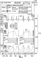
- the GUI 402 may also be configured to display waveforms next to a side rectangle having a particular color and labelled by a physiologic parameter to which the waveform pertains.
- the GUI includes the waveform 430 for heart rate (HR), the waveform 432 for End-tidal CO2 (EtCO2), which indicates the partial pressure or maximal concentration of carbon dioxide (CO2) at the end of an exhaled breath, and the waveform 434 for SpO2.
- the GUI 402 may also display NIBP values for a patient or person being monitored and/or treated.
- the GUI 402 may display a navigation task bar 418 at the bottom of the GUI 402.
- the navigation task bar 418 may have various tabs and menu options. As shown, the navigation task bar 418 includes a menu button 436, a print button 438, a 12-Lead button 440, a generic event button 442, an events button 444, an alarms button 446, and therapy button 448.
- Figure 8 illustrates a flow chart of a method 800 for detecting the end-of-life a battery unit of a medical device, according to example implementations.
- the method 800 represents an example method that may include one or more operations, functions, or actions, as depicted by one or more of blocks 802-806, each of which may be performed by any of the medical devices or systems described herein.
- medical device 202 depicted in Figure 2 may enable execution of method 800.
- each block of the flowchart may represent a module, a segment, or a portion of program code, which includes one or more instructions executable by one or more processors for implementing specific logical functions or steps in the process.
- the program code may be stored on any type of computer readable medium, for example, such as a storage device including a disk or hard drive.
- each block may represent circuitry that is wired to perform the specific logical functions in the process.
- Alternative implementations are included within the scope of the example implementations of the present application in which functions may be executed out of order from that shown or discussed, including substantially concurrent or in reverse order, depending on the functionality involved, as would be understood by those reasonably skilled in the art.
- the method 800 involves determining whether the cycle count satisfies a cycle count threshold.
- the medical device may compare the cycle count of a battery unit to a cycle count threshold.
- the cycle count threshold may represent the number of times a battery unit has been charged.
- the medical device may determine whether the cycle count of a battery unit of the medical device satisfies a cycle count threshold (e.g., the cycle count is equal to and/or above the cycle count threshold).
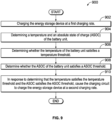
- Figure 9 illustrates a flow chart of a method 900 of charging an energy storage device of a portable medical device, according to example implementations.
- the method 900 represents an example method that may include one or more operations, functions, or actions, as depicted by one or more of blocks 902-910, each of which may be performed by any of the medical devices or systems described herein.
- the medical device 302 depicted in Figure 2 may enable execution of method 900.
- each block of the flowchart may represent a module, a segment, or a portion of program code, which includes one or more instructions executable by one or more processors for implementing specific logical functions or steps in the process.
- the program code may be stored on any type of computer readable medium, for example, such as a storage device including a disk or hard drive.
- each block may represent circuitry that is wired to perform the specific logical functions in the process.
- Alternative implementations are included within the scope of the example implementations of the present application in which functions may be executed out of order from that shown or discussed, including substantially concurrent or in reverse order, depending on the functionality involved, as would be understood by those reasonably skilled in the art.
- the method 900 involves charging the energy storage device of the portable medical device at a first charging rate.
- a medical device may be operated to monitor and provide treatment or care to a person or patient experiencing a medical condition, such as a cardiac arrest or any other cardiac rhythm abnormality.
- the medical device may include an energy storage module to store electrical energy in the form of an electrical charge for delivery of a defibrillation pulse or shock to the person being treated for a medical condition.
- the energy storage module can be charged by a charging module to a desired energy level.
- the charging module may charge the energy storage module at various rates, such as a maximum rate, a medium rate, and a slow rate.
- the method involves determining a temperature and an absolute state of charge (ASOC) of the battery unit.
- the medical device may determine the temperature and the ASCO of a battery unit of the medical device.
- the method involves determining whether the temperature of the battery unit satisfies a temperature threshold.
- the medical device may compare the temperature of a battery unit to a temperature threshold and may determine whether the temperature of the battery unit is equal to and/or above the temperature threshold.
- the method involves determining whether the ASOC of the battery unit satisfies an ASOC threshold.
- the medical device may compare the ACOC of the battery unit to an ASOC threshold and determine whether the ASCO level of the battery unit is equal to and/or above the ASCO threshold.
- each block of the flowchart may represent a module, a segment, or a portion of program code, which includes one or more instructions executable by one or more processors for implementing specific logical functions or steps in the process.
- the program code may be stored on any type of computer readable medium, for example, such as a storage device including a disk or hard drive.
- each block may represent circuitry that is wired to perform the specific logical functions in the process.
- Alternative implementations are included within the scope of the example implementations of the present application in which functions may be executed out of order from that shown or discussed, including substantially concurrent or in reverse order, depending on the functionality involved, as would be understood by those reasonably skilled in the art.
- the method 1000 involves charging the energy storage device of a portable medical device at a first charging rate.
- a medical device may be operated to monitor and provide treatment or care to a person or patient experiencing a medical condition, such as a cardiac arrest or any other cardiac rhythm abnormality.
- the medical device may include an energy storage module to store electrical energy in the form of an electrical charge for delivery of a defibrillation pulse or shock to a person being treated for a medical condition.
- the energy storage module may be charged by a charging module to a desired energy level.
- the charging module may charge the energy storage module at various rates, such as a maximum rate, a medium rate, and a slow rate.
- the method 1000 involves determining a voltage level of a battery unit of the portable medical device during charging of the energy storage device.
- the medical device may change or alter the charging rate of the energy storage module based on the conditions and/or parameters of a battery unit. For example, the medical device may determine a voltage level of the battery unit and may alter the charging rate of the energy storage module based on the voltage of the battery unit.
- the method 1000 involves determining whether the voltage level of a battery unit satisfies a voltage level threshold. The medical device may compare the voltage of the battery unit to a voltage threshold and may determine whether the battery voltage is less than or equal to the voltage threshold.
- the method 1000 involves, in response to determining that the voltage level satisfies the voltage level threshold, adjusting the first charging rate to a second charging rate.
- the voltage of the battery unit of the medical device satisfies the voltage threshold (e.g., the voltage of the battery unit is equal to and/or above the voltage threshold)
- the medical device may be configured to alter or change the rate at which the charging module charges the energy storage device.
- the embodiments described herein can be realized in hardware, software, or a combination of hardware and software.
- the embodiments can be realized in a centralized fashion in at least one computer system or in a distributed fashion where different elements are spread across interconnected computer systems. Any kind of computer system or other apparatus adapted for carrying out the methods described herein can be employed.
- the embodiments described herein can be embedded in a computer program product, which includes all the features enabling the implementation of the operations described herein and which, when loaded in a computer system, can carry out these operations.
- each block in the flowcharts or block diagrams may represent a module, segment, or portion of code, which comprises one or more executable instructions for implementing the specified logical function or functions.
- the functions noted in a block may occur out of the order noted in the drawings. For example, the functions of two blocks shown in succession may be executed substantially concurrently, or the functions of the blocks may sometimes be executed in the reverse order, depending upon the functionality involved.
Landscapes
- Health & Medical Sciences (AREA)
- Engineering & Computer Science (AREA)
- Cardiology (AREA)
- Physics & Mathematics (AREA)
- General Physics & Mathematics (AREA)
- Life Sciences & Earth Sciences (AREA)
- Public Health (AREA)
- Veterinary Medicine (AREA)
- General Health & Medical Sciences (AREA)
- Animal Behavior & Ethology (AREA)
- Radiology & Medical Imaging (AREA)
- Heart & Thoracic Surgery (AREA)
- Biomedical Technology (AREA)
- Nuclear Medicine, Radiotherapy & Molecular Imaging (AREA)
- Power Engineering (AREA)
- Manufacturing & Machinery (AREA)
- Chemical & Material Sciences (AREA)
- Chemical Kinetics & Catalysis (AREA)
- General Chemical & Material Sciences (AREA)
- Electrochemistry (AREA)
- Electrotherapy Devices (AREA)
- Secondary Cells (AREA)
Applications Claiming Priority (1)
| Application Number | Priority Date | Filing Date | Title |
|---|---|---|---|
| US202363616383P | 2023-12-29 | 2023-12-29 |
Publications (1)
| Publication Number | Publication Date |
|---|---|
| EP4579992A1 true EP4579992A1 (fr) | 2025-07-02 |
Family
ID=93925562
Family Applications (1)
| Application Number | Title | Priority Date | Filing Date |
|---|---|---|---|
| EP24222326.1A Pending EP4579992A1 (fr) | 2023-12-29 | 2024-12-20 | Systèmes, procédés et appareil pour détecter la fin de vie d'une batterie |
Country Status (4)
| Country | Link |
|---|---|
| US (1) | US20250213871A1 (fr) |
| EP (1) | EP4579992A1 (fr) |
| AU (1) | AU2024278623A1 (fr) |
| CA (1) | CA3260414A1 (fr) |
Citations (5)
| Publication number | Priority date | Publication date | Assignee | Title |
|---|---|---|---|---|
| US20030076113A1 (en) * | 2001-09-25 | 2003-04-24 | Valenta Harry L. | Implantable energy management system and method |
| US20160149418A1 (en) * | 2014-11-20 | 2016-05-26 | Samsung Electronics Co., Ltd. | Electronic Device and Battery Management Method for the Same |
| US9806544B2 (en) * | 2015-08-14 | 2017-10-31 | Draeger Medical Systems, Inc. | Medical device battery charge indicator |
| US20210143662A1 (en) * | 2018-07-27 | 2021-05-13 | Hewlett-Packard Development Company, L.P. | Charging voltage reduction of batteries |
| US20220111219A1 (en) * | 2020-10-14 | 2022-04-14 | Hearthero, Inc. | Automated external defibrillator systems with operation adjustment features according to temperature and methods of use |
-
2024
- 2024-12-13 US US18/980,948 patent/US20250213871A1/en active Pending
- 2024-12-19 AU AU2024278623A patent/AU2024278623A1/en active Pending
- 2024-12-20 CA CA3260414A patent/CA3260414A1/en active Pending
- 2024-12-20 EP EP24222326.1A patent/EP4579992A1/fr active Pending
Patent Citations (5)
| Publication number | Priority date | Publication date | Assignee | Title |
|---|---|---|---|---|
| US20030076113A1 (en) * | 2001-09-25 | 2003-04-24 | Valenta Harry L. | Implantable energy management system and method |
| US20160149418A1 (en) * | 2014-11-20 | 2016-05-26 | Samsung Electronics Co., Ltd. | Electronic Device and Battery Management Method for the Same |
| US9806544B2 (en) * | 2015-08-14 | 2017-10-31 | Draeger Medical Systems, Inc. | Medical device battery charge indicator |
| US20210143662A1 (en) * | 2018-07-27 | 2021-05-13 | Hewlett-Packard Development Company, L.P. | Charging voltage reduction of batteries |
| US20220111219A1 (en) * | 2020-10-14 | 2022-04-14 | Hearthero, Inc. | Automated external defibrillator systems with operation adjustment features according to temperature and methods of use |
Also Published As
| Publication number | Publication date |
|---|---|
| CA3260414A1 (en) | 2025-10-30 |
| US20250213871A1 (en) | 2025-07-03 |
| AU2024278623A1 (en) | 2025-07-17 |
Similar Documents
| Publication | Publication Date | Title |
|---|---|---|
| US12403324B2 (en) | Wearable medical device (WMD) implementing adaptive techniques to save power | |
| US11160991B2 (en) | Medical device with lack-of-readiness alarm | |
| EP3981323A1 (fr) | Mécanisme de filtrage permettant d'éliminer les artefacts de compression thoracique à partir d'un signal d'entrée, procédé pour son utilisation et dispositif de compression thoracique mécanique | |
| US20040204743A1 (en) | Remotely operating external medical devices | |
| US11064932B2 (en) | Intravenous line flow sensor for advanced diagnostics and monitoring in emergency medicine | |
| US10195450B2 (en) | Adaptable clinical usage profiles for advanced defibrillators | |
| EP4126189A1 (fr) | Appareil de traitement médical portatif avec guidage interactif et fonctionnalité de réanimation cardio-pulmonaire | |
| US20260011439A1 (en) | Systems and methods for on-device real-time access and review of events during a patient treatment episode | |
| US11013931B2 (en) | Modular medical system for patient monitoring and electrical therapy delivery | |
| EP4579992A1 (fr) | Systèmes, procédés et appareil pour détecter la fin de vie d'une batterie | |
| EP4595942A1 (fr) | Systèmes, procédés et appareil pour fournir une rétroaction de traitement médical | |
| EP4600966A1 (fr) | Systèmes, procédés et appareil pour ajuster des traitements médicaux | |
| US20250256119A1 (en) | Systems and Methods for Configurable Defibrillator Displays and Patient Care Reports | |
| US20250161704A1 (en) | Automatic Lead Switching | |
| EP4579676A1 (fr) | Dispositif médical à sonifications modifiables | |
| US20260069499A1 (en) | Light-based feedback output by accessory devices | |
| US20250166767A1 (en) | Analysis and presentation of aggregated patient and device data within a system that includes a medical device | |
| US20250392085A1 (en) | Managing disconnected accessory devices during monitoring | |
| CA3259689A1 (fr) | Dispositif avec des sonifications modifiables |
Legal Events
| Date | Code | Title | Description |
|---|---|---|---|
| PUAI | Public reference made under article 153(3) epc to a published international application that has entered the european phase |
Free format text: ORIGINAL CODE: 0009012 |
|
| STAA | Information on the status of an ep patent application or granted ep patent |
Free format text: STATUS: REQUEST FOR EXAMINATION WAS MADE |
|
| 17P | Request for examination filed |
Effective date: 20241220 |
|
| AK | Designated contracting states |
Kind code of ref document: A1 Designated state(s): AL AT BE BG CH CY CZ DE DK EE ES FI FR GB GR HR HU IE IS IT LI LT LU LV MC ME MK MT NL NO PL PT RO RS SE SI SK SM TR |