EP4580047A1 - Temperaturstabilisierter opto-mechanischer oszillator - Google Patents
Temperaturstabilisierter opto-mechanischer oszillator Download PDFInfo
- Publication number
- EP4580047A1 EP4580047A1 EP24222697.5A EP24222697A EP4580047A1 EP 4580047 A1 EP4580047 A1 EP 4580047A1 EP 24222697 A EP24222697 A EP 24222697A EP 4580047 A1 EP4580047 A1 EP 4580047A1
- Authority
- EP
- European Patent Office
- Prior art keywords
- resonator
- light
- signal
- processing circuit
- photodetector
- Prior art date
- Legal status (The legal status is an assumption and is not a legal conclusion. Google has not performed a legal analysis and makes no representation as to the accuracy of the status listed.)
- Pending
Links
Images


Classifications
-
- H—ELECTRICITY
- H03—ELECTRONIC CIRCUITRY
- H03B—GENERATION OF OSCILLATIONS, DIRECTLY OR BY FREQUENCY-CHANGING, BY CIRCUITS EMPLOYING ACTIVE ELEMENTS WHICH OPERATE IN A NON-SWITCHING MANNER; GENERATION OF NOISE BY SUCH CIRCUITS
- H03B17/00—Generation of oscillations using radiation source and detector, e.g. with interposed variable obturator
-
- G—PHYSICS
- G01—MEASURING; TESTING
- G01D—MEASURING NOT SPECIALLY ADAPTED FOR A SPECIFIC VARIABLE; ARRANGEMENTS FOR MEASURING TWO OR MORE VARIABLES NOT COVERED IN A SINGLE OTHER SUBCLASS; TARIFF METERING APPARATUS; MEASURING OR TESTING NOT OTHERWISE PROVIDED FOR
- G01D5/00—Mechanical means for transferring the output of a sensing member; Means for converting the output of a sensing member to another variable where the form or nature of the sensing member does not constrain the means for converting; Transducers not specially adapted for a specific variable
- G01D5/26—Mechanical means for transferring the output of a sensing member; Means for converting the output of a sensing member to another variable where the form or nature of the sensing member does not constrain the means for converting; Transducers not specially adapted for a specific variable characterised by optical transfer means, i.e. using infrared, visible, or ultraviolet light
- G01D5/32—Mechanical means for transferring the output of a sensing member; Means for converting the output of a sensing member to another variable where the form or nature of the sensing member does not constrain the means for converting; Transducers not specially adapted for a specific variable characterised by optical transfer means, i.e. using infrared, visible, or ultraviolet light with attenuation or whole or partial obturation of beams of light
- G01D5/34—Mechanical means for transferring the output of a sensing member; Means for converting the output of a sensing member to another variable where the form or nature of the sensing member does not constrain the means for converting; Transducers not specially adapted for a specific variable characterised by optical transfer means, i.e. using infrared, visible, or ultraviolet light with attenuation or whole or partial obturation of beams of light the beams of light being detected by photocells
- G01D5/353—Mechanical means for transferring the output of a sensing member; Means for converting the output of a sensing member to another variable where the form or nature of the sensing member does not constrain the means for converting; Transducers not specially adapted for a specific variable characterised by optical transfer means, i.e. using infrared, visible, or ultraviolet light with attenuation or whole or partial obturation of beams of light the beams of light being detected by photocells influencing the transmission properties of an optical fibre
- G01D5/35306—Mechanical means for transferring the output of a sensing member; Means for converting the output of a sensing member to another variable where the form or nature of the sensing member does not constrain the means for converting; Transducers not specially adapted for a specific variable characterised by optical transfer means, i.e. using infrared, visible, or ultraviolet light with attenuation or whole or partial obturation of beams of light the beams of light being detected by photocells influencing the transmission properties of an optical fibre using an interferometer arrangement
-
- H—ELECTRICITY
- H03—ELECTRONIC CIRCUITRY
- H03B—GENERATION OF OSCILLATIONS, DIRECTLY OR BY FREQUENCY-CHANGING, BY CIRCUITS EMPLOYING ACTIVE ELEMENTS WHICH OPERATE IN A NON-SWITCHING MANNER; GENERATION OF NOISE BY SUCH CIRCUITS
- H03B5/00—Generation of oscillations using amplifier with regenerative feedback from output to input
- H03B5/02—Details
- H03B5/04—Modifications of generator to compensate for variations in physical values, e.g. power supply, load, temperature
Definitions
- the technical field of the invention concerns opto-mechanical oscillators.
- an optomechanical oscillator allows the formation of a periodic electronic signal whose amplitude and period are controlled.
- One possible application is the formation of a clock signal.
- optomechanical oscillators comprise a mechanically oscillating structure optically coupled to a light beam. Under the effect of optical coupling, a portion of the light propagating in the waveguide is mechanically extracted. Under the effect of mechanical oscillation, at a resonant frequency, the efficiency of the optical coupling varies at the resonant frequency. This results in a periodic variation in the amount of light propagating in the waveguide.
- the publication Xu et al “Ultra-sensitive chip-based photonic temperature sensor using ring resonator structures" describes an optical cavity, coupled to a straight waveguide.
- the cavity is ring-shaped. It is optically coupled to the straight waveguide, by evanescent coupling. Under the effect of a temperature variation, the optical resonance wavelength is modified. Thus, an increase in temperature leads to an increase in the resonance wavelength.
- the beam propagating in the straight waveguide is a probe beam.
- the fluctuations in the light power transmitted by the probe beam which depend on the resonance frequency, are used to determine the temperature variation of the resonant structure.
- the device described in the publication thus forms a photonic thermometer.
- the inventors propose an optomechanical oscillator that allows for better consideration of temperature variation.
- the objective may be to generate an amplitude-modulated signal with stable power and period.
- the corrector is connected to the resonator, so as to modify the resonance frequency according to the correction signal.
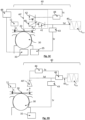
- a first embodiment of a temperature-stabilized oscillator is shown in the Figure 3A .
- the oscillator 1 comprises a waveguide 20 and a resonator 30 as described in connection with the Figures 1A and 1B
- the device comprises a first laser source 11, intended to produce a first light beam F 1 intended to be power modulated by the resonator 30.
- the first laser beam F 1 is coupled to the waveguide 20 by the first coupler 21.
- the first light beam is for example emitted at a first wavelength ⁇ 1 included in the spectral band 1520 nm - 1580 nm when the oscillator is intended for telecommunications type applications.
- the processing circuit 40 is configured to establish an output signal S out , periodic and intensity modulated.
- An important aspect of the processing circuit 40 is that it is configured so that the output signal is amplitude modulated according to a modulation frequency that is as stable as possible.
- the processing circuit 40 comprises an input formed by a photodetection circuit 40'.
- the photodetection circuit comprises one or more photodetectors, depending on the embodiments.
- the processing circuit extends between the photodetection circuit 40' and an output, delivering the output signal S or .
- the first part F' 11 of the extracted beam F' 1 is intended to generate the output signal S out , amplitude modulated. It can represent 50% of F' 1 . Preferably, the first part F' 11 is larger than the second part F' 12 .
- the first part F' 11 can correspond to at least 80% or at least 90% of the beam F' 1 , the second part F' 12 corresponding to the complementary portion.
- the first photodetector 41 is a photodiode.
- the first photodetector 41 generates a detection signal Sd, of pulsation ( ⁇ r + ⁇ ⁇ r ), which is an image of the optical beam.
- a portion of the detection signal Sd is directed to the control unit 35 of the resonator 30, and forms the feedback signal Sr.
- the feedback loop comprises a high-pass filter 43.
- the high-pass filter 43 is configured to extract a high-frequency component from the detection signal resulting from the first photodetector 41.
- high-frequency component we mean a component in a frequency range comprising the resonance f r of the resonator 30.
- the second photodetector 42 is for example a photodiode.
- the low-pass filter 44 is configured to extract a low-frequency component of the signal resulting from the second photodetector, forming the correction signal Sc.
- low-frequency component we mean a component strictly lower than the resonance frequency f r of the resonator 30, for example at a frequency lower than 100 Hz, or even 10 Hz, or even 1 Hz. This makes it possible to estimate the low-frequency component, corresponding to the variation of the modulation amplitude ⁇ P 0 under the effect of the progressive drift of the coupling bandwidth ⁇ ⁇ between the waveguide 20 and the resonator 30, under the effect of a progressive variation of the temperature of the resonator 30.
- the low-frequency component, forming the correction signal Sc is representative of the variation of optical power ⁇ P 0 . It depends on the variation of temperature dT of the resonator.
- the correction component 46 takes into account a pre-established transfer function h , linking the low frequency drift, corresponding to the variation of the static power ⁇ P 0 , under the effect of the temperature, to the high frequency drift, corresponding to the variation of the modulation frequency.
- the correction component may comprise a digital part, allowing the estimation of ⁇ ⁇ r and its taking into account to correct the pulsation of the detection signal.
- An advantage of the oscillator described in connection with the Figure 3A is that correction of the output signal is carried out from the light beam having been amplitude modulated by the resonator 30.
- FIG. 3B represents a variant of the oscillator described in connection with the Figure 3A .
- the processing circuit 40 comprises a correction branch, similar to that described in the Figure 3A .
- the processing circuit 40 comprises the photodetector 41 and the high-pass filter 43 and described in connection with the Figure 3A , forming the detection branch.
- a particularity of this variant is that the low-frequency component, forming the correction signal Sc, is not used directly to estimate the drift of the modulation frequency, but to power a correction component 48, the latter being configured to modulate the power supply of the laser 11.
- the correction signal Sc is used to feedback the power supply of the laser 11.
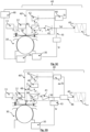
- FIG. 3C represents a variant of the oscillator described in connection with the Figure 3B .
- the processing circuit 40 comprises a correction branch, similar to that described in the Figure 3A .
- the processing circuit 40 comprises the photodetector 41 and the high-pass filter 43 and described in connection with the Figure 3A , forming the detection branch.
- the correction signal Sc is used to feedback on the resonator 30, via the corrector 48, acting on a regulation unit 36.
- the regulation unit 36 may comprise a resistor, making it possible to modulate the temperature near the resonator, or an electrode facing the air gap 34, so as to modulate the rigidity of the resonator 30, by electrostatic effect, usually called “electrostatic tuning”.
- the correction signal Sc is configured to feedback directly on the resonator 30.
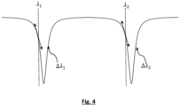
- FIG. 4 illustrates a coupling spectral band ⁇ ⁇ comprising a succession of different elementary bandwidths, without overlap.
- a first wavelength ⁇ 1 in a first bandwidth ⁇ ⁇ 1 and second first wavelength ⁇ 2 in a second bandwidth ⁇ ⁇ 2 were represented.
- each slope was marked with a double arrow.
- the second wavelength is sufficiently offset from the first wavelength such that the two wavelengths can be spectrally separated by a conventional spectral separator.
- the spectral shift is greater than 1 nm and less than 100 nm.
- the spectral shift is preferably sufficiently small to allow coupling into the waveguide 20 with the first coupler and extraction to the processing circuit 40 using the second coupler.
- the correction component 46 takes into account a pre-established response function h', linking the low frequency drift, corresponding to the variation of the static power ⁇ P' 0 of the second beam, under the effect of the temperature, to the high frequency drift, corresponding to the variation of the modulation frequency.
Landscapes
- Physics & Mathematics (AREA)
- General Physics & Mathematics (AREA)
- Semiconductor Lasers (AREA)
- Lasers (AREA)
Applications Claiming Priority (1)
| Application Number | Priority Date | Filing Date | Title |
|---|---|---|---|
| FR2315254A FR3157734A1 (fr) | 2023-12-23 | 2023-12-23 | Oscillateur opto - mécanique stabilisé en température |
Publications (1)
| Publication Number | Publication Date |
|---|---|
| EP4580047A1 true EP4580047A1 (de) | 2025-07-02 |
Family
ID=91247721
Family Applications (1)
| Application Number | Title | Priority Date | Filing Date |
|---|---|---|---|
| EP24222697.5A Pending EP4580047A1 (de) | 2023-12-23 | 2024-12-22 | Temperaturstabilisierter opto-mechanischer oszillator |
Country Status (3)
| Country | Link |
|---|---|
| US (1) | US20250207953A1 (de) |
| EP (1) | EP4580047A1 (de) |
| FR (1) | FR3157734A1 (de) |
Citations (2)
| Publication number | Priority date | Publication date | Assignee | Title |
|---|---|---|---|---|
| US20170314973A1 (en) * | 2016-04-29 | 2017-11-02 | Commissariat A L'energie Atomique Et Aux Energies Alternatives | Resonating measurement system using improved resolution |
| EP3698465B1 (de) * | 2017-10-17 | 2021-09-22 | Thales | Verbesserter hochfrequenzoszillator |
-
2023
- 2023-12-23 FR FR2315254A patent/FR3157734A1/fr active Pending
-
2024
- 2024-12-22 EP EP24222697.5A patent/EP4580047A1/de active Pending
- 2024-12-23 US US19/000,387 patent/US20250207953A1/en active Pending
Patent Citations (2)
| Publication number | Priority date | Publication date | Assignee | Title |
|---|---|---|---|---|
| US20170314973A1 (en) * | 2016-04-29 | 2017-11-02 | Commissariat A L'energie Atomique Et Aux Energies Alternatives | Resonating measurement system using improved resolution |
| EP3698465B1 (de) * | 2017-10-17 | 2021-09-22 | Thales | Verbesserter hochfrequenzoszillator |
Non-Patent Citations (4)
| Title |
|---|
| GAVARTIN, STABILIZATION OF A LINEAR NANOMECHANICAL OSCILLATOR TO ITS THERMODYNAMIC LIMIT, 2013 |
| HUANG ET AL., DIRECT STABILIZATION OF OPTOMECHANICAL OSCILLATORS, 2017 |
| LEE ET AL., LOW JITTER AND TEMPERATURE STABLE MEMS OSCILLATORS |
| XU ET AL., ULTRA-SENSITIVE CHIP-BASED PHOTONIC TEMPERATURE SENSOR USING RING RESONATOR STRUCTURES |
Also Published As
| Publication number | Publication date |
|---|---|
| FR3157734A1 (fr) | 2025-06-27 |
| US20250207953A1 (en) | 2025-06-26 |
Similar Documents
| Publication | Publication Date | Title |
|---|---|---|
| EP0455530B1 (de) | Faseroptische Messeinrichtung, Gyrometer, Navigations- und Stabilisierungssystem, Stromsensor | |
| EP0291366B1 (de) | Faseroptisches Michelson-Interferometer und dessen Anwendung, insbesondere bei der Temperaturmessung | |
| EP3520182B1 (de) | Lasersystem mit optischer rückkopplung | |
| EP2857797B1 (de) | Passiver optischer Resonanz-Messkreisel mit drei Strahlen | |
| EP3228987B1 (de) | Kompakter optischer resonanzmesskreisel mit drei frequenzen | |
| FR3070817B1 (fr) | Systeme de mesure optique a asservissement davll stabilise | |
| JP2022038157A (ja) | レーザー干渉計 | |
| TW201719109A (zh) | 光學共振腔之腔長量測裝置 | |
| FR2516233A1 (fr) | Gyroscope a laser en anneau utilisant un detecteur de phase pour minimiser le verrouillage entre faisceaux | |
| EP2635883B1 (de) | Apolarisiertes interferometrisches system und apolarisiertes interferometrisches messsystem | |
| EP4109049B1 (de) | Messsystem vom typ mems oder nems mit mehreren sensoren | |
| JP2002518856A (ja) | Wdmカプラーと後方出力光を使用した波長安定化によるスーパルミネセント・ダイオードと光増幅器 | |
| EP0415838B1 (de) | Mikroskopisches Verfahren und "Nahfeld"-Reflexionsmikroskop | |
| JP5156291B2 (ja) | フローセル中を流れるサンプルの光学的特性計測装置 | |
| EP2817590A1 (de) | Faseroptische messungsvorrichtung, gyrometer und navigations- sowie trägheitsstabilisierungssystem | |
| EP4580047A1 (de) | Temperaturstabilisierter opto-mechanischer oszillator | |
| FR2975489A1 (fr) | Composant thermo electrique a guide plasmonique, integrant un dispositif de mesure de la puissance couplee dans le mode guide | |
| EP2333564A1 (de) | Servogesteuertes bistatisches Staurohr | |
| FR2729755A1 (fr) | Gyroscope a laser en anneau et procede pour corriger des erreurs dues au blocage | |
| EP4315528B1 (de) | Verfahren zur servosteuerung einer optischen vorrichtung mit laser und resonator zur kompensation einer durch einen phasenmodulator eingeführten amplitudenmodulation | |
| WO2009063145A2 (fr) | Dispositif de detection heterodyne pour l'imagerie d'un objet par retroinjection | |
| EP1674878B1 (de) | Elektrooptische Sonde zur Messung elektrischer oder elektromagnetischer Felder mit einer Steuerung der Wellenlänge des Betriebspunkts | |
| EP0522967A1 (de) | Faseroptisches Gyrometer für Navigations- und Stabilisierungszentrum | |
| EP4671695A1 (de) | Verbessertes mems- oder nms-messsystem mit mehreren sensoren | |
| KR20010113146A (ko) | 광섬유의 굴절률 프로파일 측정 장치 |
Legal Events
| Date | Code | Title | Description |
|---|---|---|---|
| PUAI | Public reference made under article 153(3) epc to a published international application that has entered the european phase |
Free format text: ORIGINAL CODE: 0009012 |
|
| STAA | Information on the status of an ep patent application or granted ep patent |
Free format text: STATUS: REQUEST FOR EXAMINATION WAS MADE |
|
| 17P | Request for examination filed |
Effective date: 20241222 |
|
| AK | Designated contracting states |
Kind code of ref document: A1 Designated state(s): AL AT BE BG CH CY CZ DE DK EE ES FI FR GB GR HR HU IE IS IT LI LT LU LV MC ME MK MT NL NO PL PT RO RS SE SI SK SM TR |