EP4580086A1 - Système de communication optique, dispositif terminal et dispositif de station de base - Google Patents
Système de communication optique, dispositif terminal et dispositif de station de base Download PDFInfo
- Publication number
- EP4580086A1 EP4580086A1 EP23857202.8A EP23857202A EP4580086A1 EP 4580086 A1 EP4580086 A1 EP 4580086A1 EP 23857202 A EP23857202 A EP 23857202A EP 4580086 A1 EP4580086 A1 EP 4580086A1
- Authority
- EP
- European Patent Office
- Prior art keywords
- base station
- light
- station apparatus
- communication
- terminal apparatus
- Prior art date
- Legal status (The legal status is an assumption and is not a legal conclusion. Google has not performed a legal analysis and makes no representation as to the accuracy of the status listed.)
- Pending
Links
Images











Classifications
-
- H—ELECTRICITY
- H04—ELECTRIC COMMUNICATION TECHNIQUE
- H04B—TRANSMISSION
- H04B10/00—Transmission systems employing electromagnetic waves other than radio-waves, e.g. infrared, visible or ultraviolet light, or employing corpuscular radiation, e.g. quantum communication
- H04B10/80—Optical aspects relating to the use of optical transmission for specific applications, not provided for in groups H04B10/03 - H04B10/70, e.g. optical power feeding or optical transmission through water
-
- H—ELECTRICITY
- H04—ELECTRIC COMMUNICATION TECHNIQUE
- H04W—WIRELESS COMMUNICATION NETWORKS
- H04W36/00—Hand-off or reselection arrangements
- H04W36/24—Reselection being triggered by specific parameters
- H04W36/30—Reselection being triggered by specific parameters by measured or perceived connection quality data
- H04W36/302—Reselection being triggered by specific parameters by measured or perceived connection quality data due to low signal strength
-
- H—ELECTRICITY
- H04—ELECTRIC COMMUNICATION TECHNIQUE
- H04B—TRANSMISSION
- H04B10/00—Transmission systems employing electromagnetic waves other than radio-waves, e.g. infrared, visible or ultraviolet light, or employing corpuscular radiation, e.g. quantum communication
- H04B10/11—Arrangements specific to free-space transmission, i.e. transmission through air or vacuum
- H04B10/112—Line-of-sight transmission over an extended range
-
- H—ELECTRICITY
- H04—ELECTRIC COMMUNICATION TECHNIQUE
- H04B—TRANSMISSION
- H04B10/00—Transmission systems employing electromagnetic waves other than radio-waves, e.g. infrared, visible or ultraviolet light, or employing corpuscular radiation, e.g. quantum communication
- H04B10/11—Arrangements specific to free-space transmission, i.e. transmission through air or vacuum
- H04B10/112—Line-of-sight transmission over an extended range
- H04B10/1129—Arrangements for outdoor wireless networking of information
-
- H—ELECTRICITY
- H04—ELECTRIC COMMUNICATION TECHNIQUE
- H04B—TRANSMISSION
- H04B13/00—Transmission systems characterised by the medium used for transmission, not provided for in groups H04B3/00 - H04B11/00
- H04B13/02—Transmission systems in which the medium consists of the earth or a large mass of water thereon, e.g. earth telegraphy
Definitions
- the present disclosure relates to a light communication system, a terminal apparatus, and a base station apparatus.
- a known light communication system uses light (visible light in particular) as a transmission medium for communication in water, for example. Since light has high directivity, a conventional light communication system generally performs one-to-one communication with a transmission side and a reception side facing each other on the assumption that a light communication apparatus of the transmission side and a light communication apparatus of the reception side are fixed.
- Patent Document 1 JP 4-103232 A
- a base station apparatus includes a light communicator configured to perform light communication with a terminal apparatus; and a controller configured to perform connection control that establishes and/or maintains light communication connection between the terminal apparatus and the base station apparatus in such a manner that communication quality of the light communication in an uplink is prioritized over communication quality of the light communication in a downlink.
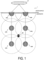
- a light communication system is a light communication system configured to perform light communication between a base station apparatus and a terminal apparatus, and includes a plurality of base station apparatuses that are three-dimensionally arranged underwater at intervals in a horizontal direction and a vertical direction. A communication area formed underwater by each of the plurality of base station apparatuses is configured to form a coverage area of the light communication in the light communication system.
- the present disclosure provides a light communication system, a terminal apparatus, and a base station apparatus that enable appropriate light communication between the terminal apparatus and the base station apparatus.
- each base station apparatus 200 may transmit a synchronization light signal and/or a reference light signal unique to each base station apparatus 200 in all directions from all light communicators.
- the terminal apparatus 100 may specify the direction of the base station apparatus 200 based on these light signals, specify the light communicator of the terminal apparatus 100 associated with the direction, and perform light communication with the base station apparatus 200 using the specified light communicator.
- FIG. 2 is a diagram schematically illustrating a transmission operation of the terminal apparatus 100 in the UL according to the present embodiment.
- a plurality of light communicators 101 (light communicators 101a, 101b, and ...) is arranged in a transparent housing 150, and the light communicators 101 perform light communication with the base station apparatus 200 via the housing 150.
- the plurality of light communicators 101 is aligned in an array along a curved inner surface 2a of the housing 150, and have optical axes directed toward respectively different directions.
- the optical axis of each light communicator 101 is directed toward a normal direction of the curved surface of the housing 150.
- FIG. 3 is a diagram illustrating a block configuration example of the base station apparatus 200 according to the present embodiment.
- the base station apparatus 200 includes a plurality of light communicators 201 (201#0, 201#1, and ...), a controller 230, and a backhaul communicator 240.
- the base station apparatus 200 may include a battery for supplying electrical power necessary for the base station apparatus 200 to operate.
- the plurality of light communicators 201 are arranged so that directivities (optical axes) of the light communication are directed toward respectively different directions.
- Each light communicator 201 performs light communication (visible light communication in the present embodiment) with the terminal apparatus 100 under control of the controller 230.
- Each light communicator 201 includes a light receiver 210 and a light emitter 220. Since each light communicator 201 is configured likewise, the configuration of the light communicator 201#0 will be described hereinafter.
- a light receiver 210#0 of the light communicator 201#0 receives a light signal (a visible light signal in the present embodiment) from the terminal apparatus 100, and outputs the received signal to the controller 230.
- the light receiver 210#0 includes at least one light receiving element 211#0 and a receiver 212#0.
- the light receiving element 211#0 may include a Photo Diode (PD) and a peripheral circuit thereof.
- the light receiving element 211#0 receives a light signal, converts the received light signal into an electrical signal (received signal), and outputs the received signal to the receiver 212#0.
- PD Photo Diode
- the optical axis of the light receiving element 211#0 is directed toward a predetermined direction different from that of the optical axis of a different light receiving element 211 (e.g., light receiving element 211#1).
- the receiver 212#0 may include a Field Programmable Gate Array (FPGA) and/or a System-on-a-chip (SoC).
- FPGA Field Programmable Gate Array
- SoC System-on-a-chip
- the receiver 212#0 converts the received signal output by each light receiving element 211#0, performs signal processing on the converted received signal, and outputs the processed received signal to the controller 230. At least part of the receiver 212#0 may be integrated with a different receiver 212 (e.g., receiver 212#1) or may be integrated with a transmitter 222.
- the light emitter 220#0 of the light communicator 201#0 transmits a light signal (a visible light signal in the present embodiment) to the terminal apparatus 100 under control of the controller 230.
- the light emitter 220#0 includes at least one light emitting element 221#0 and a transmitter 222#0.
- the light emitting element 221#0 may include a Laser Diode (LD) or a Light Emitting Diode (LED), and a peripheral circuit thereof.
- the light emitting element 221#0 converts an electrical signal (transmission signal) output by the transmitter 222#0 for light communication into a light signal, and transmits the light signal.
- LD Laser Diode
- LED Light Emitting Diode
- the controller 230 controls an overall operation of the base station apparatus 200.
- the operation of the above-described base station apparatus 200 and a below-described operation of the base station apparatus 200 may be operations performed under control of the controller 230.
- the controller 230 controls a plurality of light communicators 201.
- the controller 230 includes at least one processor 231 and at least one memory 232.
- the memory 232 stores a program to be executed by the processor 231 and information to be used for processing by the processor 231.
- the processor 231 may include a digital signal processor and a Central Processing Unit (CPU).
- the digital signal processor performs modulation and demodulation, coding and decoding, and the like on digital signals.
- the backhaul communicator 240 performs backhaul communication (wired communication and/or wireless communication) via a backhaul line under control of the controller 230.
- the backhaul communicator 240 may include a network communicator 241 that performs communication with the network 10 (e.g., core network), and an inter-base station communicator 242 that performs inter-base station communication with a neighboring base station.
- the network communicator 241 receives from the network 10 data to be transmitted to the terminal apparatus 100, and outputs the received data to the controller 230.
- the network communicator 241 transmits to the network 10 the data received by the light communicator 201 from the terminal apparatus 100.
- the controller 230 performs connection control for establishing and/or maintaining light communication connection between the terminal apparatus 100 and the base station apparatus 200 so as to prioritize communication quality of light communication in the uplink (UL) over communication quality of light communication in the downlink (DL). Details of such connection control will be described below.
- FIG. 4 is a diagram illustrating an outer appearance configuration example of the base station apparatus 200 according to the present embodiment.
- the base station apparatus 200 includes a housing 250 of a spherical shape, and the plurality of light communicators 201 aligned in an array on a curved surface of the housing 250.
- the housing 250 may be formed into a hemispherical shape.
- Each light communicator 201 is provided with a set of the at least one light receiving element 211 and the at least one light emitting element 221. Such a configuration enables the base station apparatus 200 to perform light communication with the terminal apparatuses 100 in various directions.
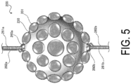
- FIG. 5 is a diagram illustrating a first variation of the outer appearance configuration of the base station apparatus 200 according to the present embodiment.
- the base station apparatus 200 includes a hook portion 260a provided at an upper end of the housing 250, a hook portion 260b provided at a lower end of the housing 250, a cable 262a extending upward from the housing 250, and a cable 262b extending downward from the housing 250.
- the cable 262a and the cable 262b may be formed as optical fibers.
- the cable 262a is used for inter-base station communication with a neighboring base station on an upper side
- the cable 262b is used for inter-base station communication with a neighboring base station on a lower side.
- the base station apparatus 200 may relay data received from the neighboring base station on the upper side via the cable 262a to the neighboring base station on the lower side via the cable 262b.
- the base station apparatus 200 may relay data received from the neighboring base station on the lower side via the cable 262b to the neighboring base station on the upper side via the cable 262a.
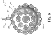
- the base station apparatus 200 includes the hook portion 260a provided at the upper end of the housing 250, the hook portion 260b provided at the lower end of the housing 250, and a laser communication device 263 provided on the upper side of the housing 250.
- the laser communication device 263 is used for inter-base station communication with the neighboring base station on the upper side.
- FIG. 9 is a diagram illustrating a first variation of an outer appearance configuration example of the terminal apparatus 100 according to the present embodiment.
- FIG. 10 is a diagram illustrating a second variation of the outer appearance configuration example of the terminal apparatus 100 according to the present embodiment.
- the terminal apparatus 100 includes the housing 150 of the spherical shape, and the mechanism portion 140 connected with the housing 150 with a cable 160 interposed therebetween.
- the housing 150 has a spherical shape.
- the housing 150 includes on the surface thereof the plurality of light communicators 101 arranged in a distributed manner. Each light communicator 101 is provided with a set of at least one light receiving element 111 and at least one light emitting element 121.
- FIG. 11 is a diagram illustrating DL communication that is an example of light communication according to the present embodiment.
- the cross section of the base station apparatus 200 and the cross section of the terminal apparatus 100 are schematically illustrated for DL communication.
- the plurality of light emitters 220 are arranged in the base station apparatus 200 such that, as a distance between the one light emitter 220 and a different light emitter 220 becomes long, an angle formed by the optical axis of the one light emitter 220 and the optical axis of the different light emitter 220 increases.
- the angle formed by the optical axis of a light emitter 220#0 and the optical axis of the light emitter 220#2 that is not adjacent to the light emitter 220#0 is larger than the angle formed by the optical axis of the light emitter 220#0 and the optical axis of a light emitter 220#1 that is adjacent to the light emitter 220#0.
- the base station apparatus 200 associates with the terminal apparatus 100 a light emitter 220#4 (light communicator #4) associated with the direction in which the terminal apparatus 100 is located, and performs light communication with the terminal apparatus 100 using the light emitter 220#4 (light communicator #4).
- the terminal apparatus 100 associates with the base station apparatus 200 the light receiver 110#0 (light communicator #0) associated with the direction in which the base station apparatus 200 is located, and performs light communication with the base station apparatus 200 using the light receiver 110#0 (light communicator #0).
- FIG. 12 is a diagram illustrating a configuration example of a communication frame used by the light communication system 1 according to the present embodiment. Although one communication frame includes 10 time slots will be described below in the illustrated example, the number of time slots constituting one communication frame is not limited to 10. Note that each time slot includes a predetermined number of symbol sections.
- the communication frame includes one synchronization slot (Sync.), one control slot (Ctrl.), four DL slots #0 to #3, and four UL slots #0 to #3.
- UL slots in a communication frame may be provided more than DL slots.
- the synchronization slot is a time slot in which the base station apparatus 200 transmits a synchronization light signal (and a reference light signal unique to the base station apparatus).
- the terminal apparatus 100 identifies the base station apparatus 200 based on the synchronization light signal received from the base station apparatus 200, and establishes or maintains synchronization with the base station apparatus 200 using the synchronization light signal.
- the reference light signal unique to the base station apparatus may be transmitted in all slots other than the UL slot.
- the reference light signal is used by the terminal apparatus 100 to measure a reception intensity (reference signal intensity) from the base station apparatus 200.
- the light communication system 1 performs selection of a connection destination base station (serving base station) and maintenance of light communication connection under a condition that UL communication becomes good to support an application such as video upload that heavily depends on UL communication. More specifically, when the terminal apparatus 100 estimates UL communication quality of the base station apparatus 200, the terminal apparatus 100 selects the base station apparatus 200 suitable for a condition that the UL communication becomes good, and establishes the light communication connection with the selected base station apparatus 200.
- connection control based on the reception strength of DL radio waves received by the terminal apparatus 100 from the base station apparatus 200 is performed. That is, the terminal apparatus 100 establishes connection with the base station apparatus 200 that is the transmission source of the reference signal having the highest DL reception strength.
- the base station apparatus 200a and the base station apparatus 200b located on the right side of the base station apparatus 200a are underwater.
- the distance between the terminal apparatus 100 and the base station apparatus 200a is equal to the distance between the terminal apparatus 100 and the base station apparatus 200b.
- Light (ambient light) from light sources located on a diagonally upper right side of the base station apparatus 200b enters the terminal apparatus 100 and each base station apparatus 200.
- the light source is assumed to be in water, but may also be above the water surface.
- the terminal apparatus 100 transmits a UL light signal from the own light communicator 101a associated with the direction of the base station apparatus 200a, and the base station apparatus 200a receives the UL light signal by the own light communicator 201a associated with the direction of the terminal apparatus 100. It is assumed that the terminal apparatus 100 transmits a UL light signal from the own light communicator 101b associated with the direction of the base station apparatus 200b, and the base station apparatus 200b receives the UL light signal by the own light communicator 201b associated with the direction of the terminal apparatus 100.
- the distances between the terminal apparatus 100 and the respective base station apparatuses 200a are equal, so that, when there is no solar noise, it can be assumed that the communication quality of the UL light signal received by the light communicator 201a of the base station apparatus 200a is equal to the communication quality of the UL light signal received by the light communicator 201b of the base station apparatus 200b.
- the optical axis of the light communicator 201a of the base station apparatus 200a is directed to a right direction, and therefore the ambient light from the light source enters as a noise signal. Therefore, the communication quality of the UL light signals received by the light communicator 201a of the base station apparatus 200a deteriorates.
- the optical axis of the light communicator 201b of the base station apparatus 200b is directed to a left direction, so that ambient light does not enter as a noise signal, and the communication quality of the UL light signal received by the light communicator 201b of the base station apparatus 200b does not deteriorate.
- the terminal apparatus 100 connects to the base station apparatus 200b instead of the base station apparatus 200a.
- the controller 130 of the terminal apparatus 100 estimates the UL communication quality that is the reception quality of the UL light signal received by the base station apparatus 200 from the terminal apparatus 100, and uses the estimated UL communication quality for connection control.
- the controller 130 of the terminal apparatus 100 estimates the UL communication quality based on the reception statuses in the plurality of own light communicators 101.
- the controller 130 of the terminal apparatus 100 estimates the UL communication quality for each of the plurality of base station apparatuses 200, selects the base station apparatus 200 whose UL communication quality satisfies a predetermined criterion from the plurality of base station apparatuses 200, and tries to connect to the selected base station apparatus 200.
- the predetermined criterion is a condition that UL communication quality is the highest among the plurality of base station apparatuses 200.
- the predetermined criterion may be a condition that UL communication quality is higher than a threshold value.
- FIG. 15 is a diagram for explaining an estimation operation of UL communication quality performed by the terminal apparatus 100 according to the present embodiment.
- the light communicator 101a (light receiver 110) of the terminal apparatus 100 receives the DL light signal from the light communicator 201a (light emitter 220) of the base station apparatus 200, more specifically, the reference light signal.
- the controller 130 of the terminal apparatus 100 measures the reference signal intensity that is the reception intensity of the reference light signal in the light communicator 101a (first light communicator) that receives the reference light signal from the base station apparatus 200.
- the light communicator 101a is a light communicator that is scheduled to be used for light communication with the base station apparatus 200.
- the controller 130 of the terminal apparatus 100 estimates the ambient light noise intensity that is the reception intensity of ambient light in the base station apparatus 200 based on the reception intensity in the light communicator 101b (second light communicator) different from the light communicator 101a.
- the light communicator 101b is a light communicator 101 whose optical axis is directed toward a direction opposite to the direction toward which the optical axis of the light communicator 101a is directed. It can be assumed that the ambient light entering the light communicator 101b (light receiver 110) also enters the light communicator 201a (light receiver 210) of the base station apparatus 200 likewise, so that the reception intensity in the light communicator 101a on the opposite side to the light communicator 101b can be estimated as the ambient light noise intensity.
- the terminal apparatus 100 uses the ambient light noise intensity measured by the light communicator 101b (light receiver 110) of the terminal apparatus 100 facing the same direction as that of the light communicator 201a (light receiver 210) of the base station apparatus 200 as an estimation value of the ambient light noise received by the light communicator 201a (light receiver 210) of the base station apparatus 200.
- the terminal apparatus 100 can compare the UL communication quality of the respective base station apparatuses 200 in the surroundings before trying connection, and select the base station apparatus 200 that the terminal apparatus 100 needs to be connected.
- FIG. 16 is a diagram for explaining an operation of selecting the light communicator 101 (light receiver 110) for noise estimation in the terminal apparatus 100 according to the present embodiment.
- the number of the light communicators 101 of the terminal apparatus 100 is smaller than the number of the light communicators 101 of the terminal apparatus 100 illustrated in FIG. 15 .
- the controller 130 of the terminal apparatus 100 registers as a pair in advance the light communicators 101 (light receivers 110) whose optical axes are directed toward opposite directions to each other, and selects for noise estimation the light communicator 101 (light receiver 110) paired with the light communicator 101 (light receiver 110) that has received the reference light signal.
- a light communicator 101 (light receiver 110) #0 and a light communicator 101 (light receiver 110) #0' are registered as a pair.
- a light communicator 101 (light receiver 110) #1 and a light communicator 101 (light receiver 110) #1' are registered as a pair
- a light communicator 101 (light receiver 110) #2 and a light communicator 101 (light receiver 110) #2' are registered as a pair
- a light communicator 101 (light receiver 110) #3 and a light communicator 101 (light receiver 110) #3' are registered as a pair
- a light communicator 101 (light receiver 110) #4 and a light communicator 101 (light receiver 110) #4' are registered as a pair
- a light communicator 101 (light receiver 110) #5 and a light communicator 101 (light receiver 110) #5' are registered as a pair
- a light communicator 101 (light receiver 110) #6 and a light communicator 101 (light receiver 110) #6' are registered
- FIG. 17 is a diagram illustrating an example of an operation flow of the terminal apparatus 100 according to the present embodiment.
- step S1 the controller 130 of the terminal apparatus 100 measures the reference signal intensity in the light communicator 101a that receives the reference light signal from the base station apparatus 200.
- step S2 the controller 130 of the terminal apparatus 100 measures the reception intensity in the light communicator 101b on the opposite side (i.e., a pair) to the light communicator 101a that receives the reference light signal from the base station apparatus 200.
- step S3 the controller 130 of the terminal apparatus 100 estimates the ambient light noise intensity in the base station apparatus 200 based on the reception intensity measured in step S2.
- the reception intensity measured in step S2 may be estimated as is as the ambient light noise intensity in the base station apparatus 200.
- step S4 the controller 130 of the terminal apparatus 100 estimates UL communication quality based on the reference signal intensity measured in step S1 and the ambient light noise intensity estimated in step S3 according to above-described Equation (1).
- step S5 the controller 130 of the terminal apparatus 100 determines whether there is the different light communicator 101 that receives a reference light signal from the different base station apparatus 200. That is, the controller 130 of the terminal apparatus 100 determines whether there is a different candidate base station.
- the controller 130 of the terminal apparatus 100 estimates the UL communication quality of the different base station apparatus 200 (steps S1 to S4). In this way, the controller 130 of the terminal apparatus 100 estimates the UL communication quality for each of the plurality of candidate base station apparatuses 200.
- step S6 the controller 130 of the terminal apparatus 100 ranks the UL communication quality of each of the plurality of candidate base station apparatuses 200 (that is, ranks the UL communication quality in descending order).
- step S7 the controller 130 of the terminal apparatus 100 determines (selects) the base station apparatus 200 as a connection destination based on a ranking result in step S6. For example, the controller 130 determines the base station apparatus 200 having the highest UL communication quality as the connection destination.
- step S8 the controller 130 of the terminal apparatus 100 tries connection to the base station apparatus 200 determined in step S7.
- the terminal apparatus 100 establishes light communication connection with the base station apparatus 200 by transmitting a connection request message to the base station apparatus 200 and receiving a response message from the base station apparatus 200.
- the controller 130 of the terminal apparatus 100 may select the second base station apparatus 200 in the ranking, and try to connect to the base station apparatus 200.
- FIG. 18 is a diagram for explaining an operation according to the present variation.
- the ambient light is measured for a certain time to calculate an average intensity and use a value of the average intensity for noise estimation instead of using an instantaneous ambient light measurement result. That is, the controller 130 of the terminal apparatus 100 estimates the ambient light noise intensity by averaging a plurality of measurement values obtained by measuring the reception intensity in the light communicator 101b on the opposite side (i.e., a pair) to the light communicator 101a that receives the reference light signal from the base station apparatus 200 a plurality of times within a predetermined period (step S3 in FIG. 17 ).
- the base station apparatus 200 suitable for UL communication can be selected without being influenced by instantaneous ambient light.
- the ambient light noise intensity of the base station apparatus 200 is estimated using the light receiver 110 that the ambient light enters, the estimated ambient light noise intensity usually increases due to the influence of the entering ambient light, and therefore the estimated UL reception quality deteriorates.
- step S11 the controller 130 of the terminal apparatus 100 determines whether ambient light is in a shielded state where the ambient light entering the base station apparatus 200 is shielded by the terminal apparatus 100.
- step S11: YES the controller 130 of the terminal apparatus 100 corrects the ambient light noise intensity estimated in step S3 to a predetermined alternative value in step S12.
- the controller 130 of the terminal apparatus 100 determines that the ambient light is in the shielded state based on a fact that a condition 1 (first condition) has been satisfied that the ambient light noise intensity estimated in step S3 is a first threshold value or more and at least the reception intensity of the ambient light in the light communicator 101 (first light communicator) used to measure the reference signal intensity in step S1 is less than a second threshold value. That is, the controller 130 of the terminal apparatus 100 determines that the ambient light is in the shielded state based on a fact that the condition 1 has been satisfied that the estimated ambient light noise is sufficiently large, yet the ambient light noise in the other light receiver is sufficiently small.
- the light communicator 101 used for measurement of the reference signal intensity in step S1 is the light communicator 101 on the opposite side to the light communicator 101 (second light communicator) used for estimation of the ambient light noise intensity in step S3.
- the terminal apparatus 100 is influenced by the ambient light as a whole, which can be regarded as that this state does not correspond to the shielded state.
- Condition 2a The distance between the terminal apparatus 100 and the base station apparatus 200 is sufficiently short.
- the controller 130 of the terminal apparatus 100 may regard that the distance between the terminal apparatus 100 and the base station apparatus 200 is sufficiently short and determine that the condition 2a has been satisfied.
- the controller 130 of the terminal apparatus 100 uses the reference signal intensity measured in step S1 as a value indicating the distance between the terminal apparatus 100 and the base station apparatus 200.
- a value obtained by subtracting the transmission electrical power of the reference light signal from the reference signal intensity measured in step S1 may be used as a value indicating the distance between the terminal apparatus 100 and the base station apparatus 200.
- the controller 130 of the terminal apparatus 100 determines that the ambient light is in the shielded state.
- the distance between the terminal apparatus 100 and the base station apparatus 200 is sufficiently short, it can be regarded that the ambient light readily enters the shade of terminal apparatus 100, that is, the ambient light is in a shielded state.
- Condition 2b A light receiver from which great ambient light noise has been measured is limited.
- the controller 130 of the terminal apparatus 100 uses a predetermined alternative value instead of the ambient light noise intensity estimated in step S3 (step S12).
- the predetermined alternative value may be an average value or a median value of the reception intensities in the plurality of respective light communicators 101 of the terminal apparatus 100.
- the controller 130 of the terminal apparatus 100 may acquire from the base station apparatus 200 the ambient light noise intensity derived by the base station apparatus 200, and use the ambient light noise intensity acquired from the base station apparatus 200 as the predetermined alternative value.
- the base station apparatus 200 notifies the terminal apparatus 100 of information on the ambient light noise intensity by broadcasting.
- the ambient light noise intensity derived by the base station apparatus 200 may be, for example, an average value of the ambient light intensities measured by the available light receivers 210 of the base station apparatus 200.
- the ambient light noise intensity derived by the base station apparatus 200 may be an average value of the ambient light intensities measured for each group (area) of the light receivers 210 of the base station apparatus 200.
- the base station apparatus 200 suitable for UL communication can be selected.
- a difference of the third variation of the first embodiment from the above-described first embodiment will be mainly described.
- the present variation may be implemented in combination with the above-described first embodiment or the variations thereof.
- the terminal apparatus 100 When transmission electrical power of a reference light signal is different per base station apparatus 200, if UL communication quality is estimated (more specifically, calculated according to above-described Equation (1)) without taking the transmission electrical power into account, the terminal apparatus 100 is concerned to be connected to the (distant) base station apparatus 200 having high transmission electrical power yet poor UL communication quality. Hence, in the present variation, the base station apparatus 200 transmits the transmission electrical power of the reference light signal as broadcast information.
- the controller 130 of the terminal apparatus 100 acquires from the base station apparatus 200 information indicating transmission electrical power of a reference signal in the base station apparatus 200.
- the controller 130 of the terminal apparatus 100 determines the connection destination base station apparatus 200 based on the calculated UL communication quality similarly to the above-described first embodiment.
- step S21 the base station apparatus 200a transmits broadcast information indicating the transmission electrical power of the own reference light signal.
- the terminal apparatus 100 receives the broadcast information.
- the transmission electrical power takes a small value.
- step S22 the base station apparatus 200b transmits the broadcast information indicating the transmission electrical power of the own reference light signal.
- the terminal apparatus 100 receives the broadcast information.
- the transmission electrical power takes a large value.
- step S23 the base station apparatus 200a transmits a reference light signal.
- the terminal apparatus 100 receives the reference light signal and measures the reference signal intensity.
- step S24 the base station apparatus 200b transmits a reference light signal.
- the terminal apparatus 100 receives the reference light signal and measures the reference signal intensity.
- step S25 the terminal apparatus 100 estimates UL communication quality for each of the base station apparatus 200a and the base station apparatus 200b according to above-described Equation (2), and determines the connection destination base station apparatus 200 by comparing the UL communication quality.
- the description will be continued on the assumption that the UL communication quality estimated for the base station apparatus 200a is higher than the UL communication quality estimated for the base station apparatus 200b.
- step S26 the terminal apparatus 100 determines the base station apparatus 200a as a connection destination, and transmits a connection request message to the base station apparatus 200a.
- the base station apparatus 200a receives the connection request message.
- step S27 the terminal apparatus 100 establishes light communication connection with the base station apparatus 200a.
- connection control an operation of establishing light communication connection between the terminal apparatus 100 and the base station apparatus 200 has been mainly described as an example of connection control.
- connection control an operation for maintaining light communication connection between the terminal apparatus 100 and the base station apparatus 200 will be mainly described as an example of connection control.
- the base station apparatus 200 side is concerned to perform control without taking UL prioritization connection into account.
- the base station apparatus 200 may hand over the terminal apparatus 100 to the different base station apparatus 200 having poor UL communication quality. Therefore, the base station apparatus 200 does not perform control while prioritizing DL for the terminal apparatus 100 for which connection has been established while prioritizing UL, and needs to perform control based on a condition that connection can be maintained while prioritizing UL.
- the controller 130 of the terminal apparatus 100 notifies the base station apparatus 200 of that the terminal apparatus 100 is performing the UL prioritization connection in processing of establishing connection with the base station apparatus 200.
- the base station apparatus 200 can recognize that the terminal apparatus 100 is performing the UL prioritization connection, and can perform control for maintaining the UL prioritization connection.
- FIG. 22 is a diagram illustrating an example of an operation sequence of the light communication system 1 according to the present embodiment.
- step S31 the base station apparatus 200 transmits broadcast information indicating that the base station apparatus 200 can perform connection control of prioritizing the UL communication quality.
- the terminal apparatus 100 receives the broadcast information.
- step S32 the base station apparatus 200 transmits a reference light signal.
- the terminal apparatus 100 receives the reference light signal and measures the reference signal intensity.
- step S33 the terminal apparatus 100 estimates the UL communication quality of the base station apparatus 200, and determines the base station apparatus 200 as a connection destination.
- step S34 the terminal apparatus 100 transmits to the base station apparatus 200 a connection request message including information indicating that the UL prioritization connection is being performed.
- the base station apparatus 200 receives the connection request message.
- step S35 the terminal apparatus 100 establishes light communication connection with the base station apparatus 200.
- the base station apparatus 200 configures the terminal apparatus 100 to transmit to the base station apparatus 200 a measurement report message including information indicating the UL communication quality estimated by the terminal apparatus 100.
- the base station apparatus 200 determines handover of the terminal apparatus 100 from the own base station apparatus 200 to the different base station apparatus 200 based on the measurement report message from the terminal apparatus 100.
- the base station apparatus 200 can hand over the terminal apparatus 100 to the different base station apparatus 200 having good UL communication quality.
- the controller 130 of the terminal apparatus 100 may trigger transmission of the measurement report message to the base station apparatus 200 in response to that the estimated UL communication quality has satisfied a predetermined trigger condition.
- a trigger condition may include any of the following.
- the base station apparatus 200 may notify the different base station apparatus 200 of that the terminal apparatus 100 is performing UL prioritization connection in processing of handing over the terminal apparatus 100 from the own base station apparatus 200 to the different base station apparatus 200.
- UL prioritization connection information can be shared between the base station apparatuses 200, so that the handover destination base station apparatus 200 can continue control for maintaining the UL prioritization connection.
- FIG. 23 is a diagram illustrating an example of an operation sequence of the light communication system 1 according to the present variation.
- step S41 the terminal apparatus 100 establishes light communication connection with the base station apparatus 200a by the method according to the above-described first embodiment or the variations thereof.
- the terminal apparatus 100 notifies the base station apparatus 200a of that the terminal apparatus 100 is performing the UL prioritization connection.
- step S42 the base station apparatus 200a transmits to the terminal apparatus 100 configuration information (Meas. Config) for configuring transmission of the measurement report message.
- the terminal apparatus 100 receives the configuration information.
- the configuration information may include information for configuring the trigger condition relating to the above-described UL communication quality.
- the configuration information may include information for configuring to include UL communication quality in the measurement report message.
- step S43 the base station apparatus 200a transmits a reference light signal.
- the terminal apparatus 100 receives the reference light signal, measures the reference signal intensity, and estimates the UL communication quality of the base station apparatus 200a by the method according to the above-described first embodiment or the variations thereof.
- step S47 the base station apparatus 200a transmits HO information including information indicating that the terminal apparatus 100 is performing UL prioritization connection to the base station apparatus 200b by inter-base station communication.
- the base station apparatus 200b receives the HO information.
- the base station apparatus 200a may transmit an HO request message including the HO information to the base station apparatus 200b.
- HO of the terminal apparatus 100 from the base station apparatus 200a to the base station apparatus 200b is performed.
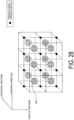
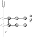
- the present embodiment is an embodiment that relates to details of above-described three dimensional arrangement of the base station apparatuses 200 (see, for example, FIG. 1 ).
- the present embodiment can be implemented in combination with the above-described first embodiment or the variations thereof.
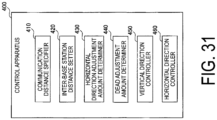
- the dead zone adjustment amount determiner 440 determines a dead zone adjustment amount (shift amount) ⁇ for arranging the base station apparatus 200 such that the vertex of each communication area in the cubic shape does not concentrate.
- the dead zone adjustment amount determiner 440 may determine the dead zone adjustment amount ⁇ based on the environmental parameter similarly to the horizontal direction adjustment amount determiner 430.
- FIG. 35 is a diagram for explaining the dead zone adjustment amount ⁇ in the horizontal direction.
- the respective base station apparatuses 200 are arranged such that the positions of the base station apparatuses adjacent in the y direction are shifted by ⁇ in the x direction.
- the movement mechanism 311 provided to the floating member 310 and/or the movement mechanism 321 provided to the weight member 320 perform adjustment of shifting the position by ⁇ in the horizontal direction.
- the horizontal direction controller 460 adjusts the position of the base station apparatus 200 in the horizontal direction by controlling the movement mechanism 311 and/or the movement mechanism 321 based on the inter-base station distance "a" configured by the inter-base station distance setter 420, the horizontal direction adjustment amount " ⁇ ” determined by the horizontal direction adjustment amount determiner 430, and the dead zone adjustment amount " ⁇ " in the horizontal direction.
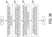
- FIG. 36 is a diagram illustrating a flow example at a time of initial installation of each base station apparatus 200.
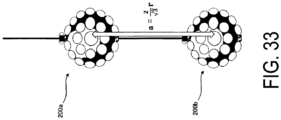
- the communication distance specifier 410 specifies a communication distance (radius "r") of light communication of the base station apparatuses 200 constituting the base station apparatus pair by performing the light communication between the base station apparatus pair whose communication areas are adjacent in the vertical direction.
- the inter-base station distance setter 420 configures the inter-base station distance "a" in the horizontal direction and the vertical direction based on the communication distance "r" specified by the communication distance specifier 410. For example, the inter-base station distance setter 420 notifies each base station apparatus 200 of the inter-base station distance "a", and each base station apparatus 200 can adjust the inter-base station distance in the vertical direction by adjusting the wire length using the adjustment mechanism 265.
- the horizontal direction adjustment amount determiner 430 determines the horizontal direction adjustment amount ⁇ based on an environmental parameter (environmental information) indicating at least one selected from the group consisting of the height of a wave, the strength of wind on water, and the speed of a water flow, in the coverage area of the light communication system 1, and calculates an inter-base station distance "a - ⁇ " in the horizontal direction.
- the inter-base station distance setter 420 notifies each base station apparatus 200 of the horizontal direction adjustment amount ⁇ , and each base station apparatus 200 moves the floating member 310 and/or the weight member 320 using the movement mechanism 311 and/or the movement mechanism 321, so that the inter-base station distance in the horizontal direction can be adjusted.
- FIG. 37 explains an operation according to the first variation of the third embodiment.
- the communication distances "r" of the base station apparatuses 200 are equal.
- turbidity may be high and the communication distance "r" may be short.
- the communication distance of the base station apparatus 200a close to the water surface is "r”
- the communication distance of the base station apparatus 200c close to the bottom of water is "r'”.
- the communication distance "r'" is shorter than the communication distance "r”. Therefore, a dead zone (coverage hole) is produced outside the communication area of the base station apparatus 200c.
- the inter-base station distance is configured without taking into account such a difference in the communication distance "r" of each base station apparatus 200, it is concerned that a dead zone is produced in the coverage area. Hence, in the present variation, an operation that can support the difference in communication distance "r" for each base station apparatus 200 is performed.
- the communication distance specifier 410 specifies the communication distance for each of a plurality of base station apparatus pairs by performing light communication with the plurality of base station apparatus pairs whose communication areas are adjacent in the vertical direction.
- the communication distance specifier 410 specifies the shortest communication distance among the communication distances specified for the plurality of base station apparatus pairs.
- the communication distance specifier 410 specifies the communication distance "r'" as the shortest communication distance.
- the inter-base station distance setter 420 configures at least the inter-base station distance in the horizontal direction.
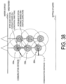
- FIG. 38 is a diagram illustrating a first configuration pattern of the inter-base station distance according to the present variation.
- the inter-base station distance is uniformly reduced, and therefore the communication area in the vertical direction in which no dead zone has been produced is also reduced.
- FIG. 41 is a diagram illustrating a third configuration pattern of the inter-base station distance according to the present variation.
- the inter-base station distance setter 420 configures the inter-base station distance only in the horizontal direction based on the shortest communication distance "r'" similarly to the above-described second configuration pattern, and configures the inter-base station distance in the vertical direction based on the communication distance "r" of each base station apparatus pair per base station apparatus pair including the base station apparatuses 200 adjacent in the vertical direction.
- the inter-base station distance in the vertical direction between the base station apparatus 200a and the base station apparatus 200b is configured based on the communication distance r specified between the base station apparatus 200a and the base station apparatus 200b.
- step S75 when it is determined that the rejection notification has been received from the terminal apparatus 100 (step S75 : YES), the base station apparatus 200 shares the reception of the rejection notification with the different base station apparatus 200, and stands by for a certain period of time in step S77. After a certain period of time passes, the base station apparatus 200 tries to change the inter-base station distance again.
- a program that causes a computer to execute each processing performed by the terminal apparatus 100, the base station apparatus 200, or the control apparatus 400 may be provided.
- the program may be recorded in a computer readable medium.
- Use of the computer readable medium enables the program to be installed on a computer.
- the computer readable medium on which the program is recorded may be a non-transitory recording medium.
- the non-transitory recording medium is not particularly limited, and may be, for example, a recording medium such as a CD-ROM or a DVD-ROM.
- the controller is configured to determine that the ambient light is in the shielded state based on a fact that a first condition has been satisfied that the ambient light noise intensity is a first threshold or more and at least the reception intensity of the ambient light in the first light communicator is less than a second threshold value.
- the predetermined alternative value is an average value or a median value of a reception intensity in each of the plurality of light communicators.
- the controller is configured to notify the selected base station apparatus of that the terminal apparatus is performing uplink prioritization connection during processing of establishing connection to the selected base station apparatus.
- the controller of the terminal apparatus is configured to trigger transmission of the measurement report message to the base station apparatus in response to that the estimated uplink communication quality has satisfied a predetermined trigger condition.
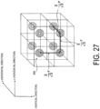
- each of the plurality of base station apparatuses is regarded as a cubic shape
- the plurality of base station apparatuses are arranged underwater such that the communication area in the cubic shape is aligned in the horizontal direction and the vertical direction to fill the coverage area.
- the plurality of base station apparatuses are arranged underwater such that each vertex of the one communication area in the cubic shape does not overlap each vertex of the other communication area in the cubic shape.
- the light communication system described in Supplementary Note 7 further includes:
Landscapes
- Engineering & Computer Science (AREA)
- Computer Networks & Wireless Communication (AREA)
- Signal Processing (AREA)
- Physics & Mathematics (AREA)
- Electromagnetism (AREA)
- Computing Systems (AREA)
- Optical Communication System (AREA)
- Mobile Radio Communication Systems (AREA)
Applications Claiming Priority (3)
| Application Number | Priority Date | Filing Date | Title |
|---|---|---|---|
| JP2022134686 | 2022-08-26 | ||
| JP2022171108 | 2022-10-26 | ||
| PCT/JP2023/029025 WO2024043089A1 (fr) | 2022-08-26 | 2023-08-09 | Système de communication optique, dispositif terminal et dispositif de station de base |
Publications (1)
| Publication Number | Publication Date |
|---|---|
| EP4580086A1 true EP4580086A1 (fr) | 2025-07-02 |
Family
ID=90013132
Family Applications (1)
| Application Number | Title | Priority Date | Filing Date |
|---|---|---|---|
| EP23857202.8A Pending EP4580086A1 (fr) | 2022-08-26 | 2023-08-09 | Système de communication optique, dispositif terminal et dispositif de station de base |
Country Status (4)
| Country | Link |
|---|---|
| US (1) | US20260074802A1 (fr) |
| EP (1) | EP4580086A1 (fr) |
| JP (1) | JP7832336B2 (fr) |
| WO (1) | WO2024043089A1 (fr) |
Family Cites Families (8)
| Publication number | Priority date | Publication date | Assignee | Title |
|---|---|---|---|---|
| JPH04103232A (ja) | 1990-08-22 | 1992-04-06 | Nec Corp | レーザ水中通信装置 |
| JPH0993196A (ja) * | 1995-09-25 | 1997-04-04 | Sharp Corp | 光空間伝送装置 |
| US9438337B2 (en) * | 2014-05-31 | 2016-09-06 | Cisco Technology, Inc. | Control system for multi-beam free space optical endpoint |
| CN105515680B (zh) | 2016-01-08 | 2018-07-31 | 暨南大学 | 基于蓝光led可见光通信的水下物联网系统 |
| FR3069401B1 (fr) * | 2017-07-21 | 2019-08-30 | Commissariat A L'energie Atomique Et Aux Energies Alternatives | Methode d'ordonnancement pour voies montante et descendante d'un systeme de transmission optique |
| WO2019204319A1 (fr) | 2018-04-16 | 2019-10-24 | The Regents Of The University Of California | Systèmes de communication optique en espace libre sous-marins |
| JP7594283B2 (ja) | 2021-03-04 | 2024-12-04 | フレックスジャパン株式会社 | 多用途ケープ |
| JP7708580B2 (ja) | 2021-04-30 | 2025-07-15 | ローランドディー.ジー.株式会社 | 画像転写シートおよび画像転写方法 |
-
2023
- 2023-08-09 EP EP23857202.8A patent/EP4580086A1/fr active Pending
- 2023-08-09 WO PCT/JP2023/029025 patent/WO2024043089A1/fr not_active Ceased
- 2023-08-09 JP JP2024542743A patent/JP7832336B2/ja active Active
- 2023-08-09 US US19/106,894 patent/US20260074802A1/en active Pending
Also Published As
| Publication number | Publication date |
|---|---|
| WO2024043089A1 (fr) | 2024-02-29 |
| US20260074802A1 (en) | 2026-03-12 |
| JP7832336B2 (ja) | 2026-03-17 |
| JPWO2024043089A1 (fr) | 2024-02-29 |
Similar Documents
| Publication | Publication Date | Title |
|---|---|---|
| US11929802B2 (en) | Unmanned aerial vehicle communication | |
| EP4233372B1 (fr) | Gestion de liste de cellules voisines dans des réseaux non terrestres | |
| JP6680676B2 (ja) | 無線送信局および無線通信ネットワーク | |
| KR101973719B1 (ko) | 채널 측정 방법, 셀 핸드오버 방법, 관련 장치 및 시스템 | |
| CN113169792B (zh) | 在具有仅接收器mmWave 5G BS天线的网络和其他网络中的UAV通信的方案 | |
| US20160323756A1 (en) | Radio base station, mobile station and radio communication method | |
| EP2552146B1 (fr) | Procédé de contrôle de communication et station de base à petite ou moyenne échelle | |
| EP3709680A1 (fr) | Appareil et procédé dans un système de communication sans fil, et support de stockage lisible par ordinateur | |
| AU2005205617B2 (en) | Underwater optical communications system and method | |
| JPWO2010110396A1 (ja) | アンテナ制御装置、無線通信システム及びアンテナ制御方法 | |
| EP3525358A1 (fr) | Système de communication radio, procédé de commande de communication radio, appareil de terminal mobile, appareil de station de base et appareil de commande | |
| CN111034346A (zh) | 移动小区回程协调 | |
| EP2367375A2 (fr) | Station de base sans fil et procédé de communication | |
| EP4580086A1 (fr) | Système de communication optique, dispositif terminal et dispositif de station de base | |
| GB2346511A (en) | Communication system using mobile repeaters | |
| US12362818B2 (en) | Relaying communications with mobile objects | |
| CN113556189A (zh) | 无人机的天线调整方法和装置 | |
| EP4611284A1 (fr) | Système de communication optique, dispositif de station de base et dispositif de gestion | |
| EP4625843A1 (fr) | Système de communication optique cellulaire, dispositif de station de base, et dispositif terminal | |
| EP3272167B1 (fr) | Dispositif et procédé de communication sans fil | |
| US20260031918A1 (en) | Ue positioning | |
| EP4597882A1 (fr) | Dispositif de communication optique, procédé de communication optique et programme | |
| EP4693955A1 (fr) | Système de communication optique, dispositif de station de base et dispositif terminal | |
| JP7813897B2 (ja) | 光通信システム、端末装置、及び基地局装置 | |
| JP7829032B2 (ja) | 光通信装置、光通信方法、及び光通信プログラム |
Legal Events
| Date | Code | Title | Description |
|---|---|---|---|
| STAA | Information on the status of an ep patent application or granted ep patent |
Free format text: STATUS: THE INTERNATIONAL PUBLICATION HAS BEEN MADE |
|
| PUAI | Public reference made under article 153(3) epc to a published international application that has entered the european phase |
Free format text: ORIGINAL CODE: 0009012 |
|
| STAA | Information on the status of an ep patent application or granted ep patent |
Free format text: STATUS: REQUEST FOR EXAMINATION WAS MADE |
|
| 17P | Request for examination filed |
Effective date: 20250226 |
|
| AK | Designated contracting states |
Kind code of ref document: A1 Designated state(s): AL AT BE BG CH CY CZ DE DK EE ES FI FR GB GR HR HU IE IS IT LI LT LU LV MC ME MK MT NL NO PL PT RO RS SE SI SK SM TR |
|
| DAV | Request for validation of the european patent (deleted) | ||
| DAX | Request for extension of the european patent (deleted) |