EP4580106A1 - Verfahren und vorrichtung zur drahtlosen kommunikation - Google Patents
Verfahren und vorrichtung zur drahtlosen kommunikation Download PDFInfo
- Publication number
- EP4580106A1 EP4580106A1 EP23852021.7A EP23852021A EP4580106A1 EP 4580106 A1 EP4580106 A1 EP 4580106A1 EP 23852021 A EP23852021 A EP 23852021A EP 4580106 A1 EP4580106 A1 EP 4580106A1
- Authority
- EP
- European Patent Office
- Prior art keywords
- csi
- symbol
- reportconfig
- physical layer
- csi reporting
- Prior art date
- Legal status (The legal status is an assumption and is not a legal conclusion. Google has not performed a legal analysis and makes no representation as to the accuracy of the status listed.)
- Pending
Links
Images

Classifications
-
- H—ELECTRICITY
- H04—ELECTRIC COMMUNICATION TECHNIQUE
- H04W—WIRELESS COMMUNICATION NETWORKS
- H04W24/00—Supervisory, monitoring or testing arrangements
- H04W24/10—Scheduling measurement reports ; Arrangements for measurement reports
-
- H—ELECTRICITY
- H04—ELECTRIC COMMUNICATION TECHNIQUE
- H04L—TRANSMISSION OF DIGITAL INFORMATION, e.g. TELEGRAPHIC COMMUNICATION
- H04L1/00—Arrangements for detecting or preventing errors in the information received
- H04L1/12—Arrangements for detecting or preventing errors in the information received by using return channel
- H04L1/16—Arrangements for detecting or preventing errors in the information received by using return channel in which the return channel carries supervisory signals, e.g. repetition request signals
- H04L1/1607—Details of the supervisory signal
-
- H—ELECTRICITY
- H04—ELECTRIC COMMUNICATION TECHNIQUE
- H04L—TRANSMISSION OF DIGITAL INFORMATION, e.g. TELEGRAPHIC COMMUNICATION
- H04L1/00—Arrangements for detecting or preventing errors in the information received
- H04L1/12—Arrangements for detecting or preventing errors in the information received by using return channel
- H04L1/16—Arrangements for detecting or preventing errors in the information received by using return channel in which the return channel carries supervisory signals, e.g. repetition request signals
- H04L1/18—Automatic repetition systems, e.g. Van Duuren systems
- H04L1/1829—Arrangements specially adapted for the receiver end
- H04L1/1864—ARQ related signaling
-
- H—ELECTRICITY
- H04—ELECTRIC COMMUNICATION TECHNIQUE
- H04L—TRANSMISSION OF DIGITAL INFORMATION, e.g. TELEGRAPHIC COMMUNICATION
- H04L5/00—Arrangements affording multiple use of the transmission path
-
- H—ELECTRICITY
- H04—ELECTRIC COMMUNICATION TECHNIQUE
- H04L—TRANSMISSION OF DIGITAL INFORMATION, e.g. TELEGRAPHIC COMMUNICATION
- H04L5/00—Arrangements affording multiple use of the transmission path
- H04L5/003—Arrangements for allocating sub-channels of the transmission path
- H04L5/0048—Allocation of pilot signals, i.e. of signals known to the receiver
- H04L5/0051—Allocation of pilot signals, i.e. of signals known to the receiver of dedicated pilots, i.e. pilots destined for a single user or terminal
-
- H—ELECTRICITY
- H04—ELECTRIC COMMUNICATION TECHNIQUE
- H04L—TRANSMISSION OF DIGITAL INFORMATION, e.g. TELEGRAPHIC COMMUNICATION
- H04L5/00—Arrangements affording multiple use of the transmission path
- H04L5/003—Arrangements for allocating sub-channels of the transmission path
- H04L5/0053—Allocation of signalling, i.e. of overhead other than pilot signals
- H04L5/0055—Physical resource allocation for ACK/NACK
-
- H—ELECTRICITY
- H04—ELECTRIC COMMUNICATION TECHNIQUE
- H04L—TRANSMISSION OF DIGITAL INFORMATION, e.g. TELEGRAPHIC COMMUNICATION
- H04L5/00—Arrangements affording multiple use of the transmission path
- H04L5/003—Arrangements for allocating sub-channels of the transmission path
- H04L5/0053—Allocation of signalling, i.e. of overhead other than pilot signals
- H04L5/0057—Physical resource allocation for CQI
-
- H—ELECTRICITY
- H04—ELECTRIC COMMUNICATION TECHNIQUE
- H04W—WIRELESS COMMUNICATION NETWORKS
- H04W52/00—Power management, e.g. Transmission Power Control [TPC] or power classes
- H04W52/02—Power saving arrangements
- H04W52/0203—Power saving arrangements in the radio access network or backbone network of wireless communication networks
- H04W52/0206—Power saving arrangements in the radio access network or backbone network of wireless communication networks in access points, e.g. base stations
Definitions
- the present disclosure relates to methods and apparatuses in wireless communication systems, particularly to schemes and apparatuses of Channel Status Information (CSI) in wireless communication systems.
- CSI Channel Status Information
- the priority of the CSI report is defined, which is used to determine whether to assign CSI Processing Unit (CPU) resources to the corresponding CSI Reporting for updating, or whether to drop the corresponding CSI report.
- CPU CSI Processing Unit
- NR R (release) 15 and R16 the ability of UE to simultaneously perform CSI computing capabilities is introduced to determine the number of CSI Reporting that UE can update at the same time.
- the inventors have found, through research, that in order to reduce the energy consumption of the base station, it is possible to trigger periodic CSI Reporting using dynamic signaling, at which point the CPU occupation time needs to be further adjusted.
- the present application can also be used for other types of cellular systems such as Long Term Evolution (LTE). Further, the adoption of a unified UE reporting scheme can reduce complexity or improve performance.
- LTE Long Term Evolution
- the embodiments of any of the nodes of the present application and the features of the embodiments may be applied to any of the other nodes. In the absence of conflicts, the embodiments of the present application and the features in the embodiments may be arbitrarily combined with each other.
- a method for use in a first node for wireless communication wherein it comprises:
- the above methods enable dynamic triggering or activation of periodic CSI Reporting, improving the feedback efficiency of CSI and reducing redundant overhead; further, it is beneficial to save power consumption of base stations or UE.
- the above approach avoids the premature occupancy of the CPU by periodic CSI Reporting, thereby avoiding the inability of a higher priority CSI to be assigned to the CPU.
- the above methods can avoid misunderstandings between the two parties, and the reasons for such misunderstandings include the leakage or false alarm of the first DCI.
- the first HARQ-ACK is an ACK.
- the time domain resource occupied by the first HARQ-ACK is a time domain resource occupied by PUSCH carrying the first HARQ-ACK.
- the time domain resource occupied by the first HARQ-ACK is a time domain resource occupied by PUCCH carrying the first HARQ-ACK.
- the first HARQ-ACK is used to indicate whether the first DCI is properly encoded.
- the first HARQ-ACK is used to indicate whether the Physical Downlink Shared Channel (PDSCH) scheduled by the first DCI is properly encoded.
- PDSCH Physical Downlink Shared Channel
- the above method can reduce the redundant overhead caused by RS resources, especially periodic or semi-continuous RS resources.
- the above method can reduce the energy loss caused by the transmission of the base station side to remain on the RS resource.
- the measurement in the first RS resource group includes at least one of an interference measurement and a channel measurement.
- the method above is characterized in that the at least first CSI Reporting comprises a plurality of CSI Reporting, with the first CSI Reporting being the earliest among them; for any CSI Reporting other than the first CSI Reporting, the CSI processing unit is occupied from the target symbol until the last symbol of the target physical layer channel, and the CSI Reporting is on the target physical layer channel; the target symbol is the earliest symbol in the target occasion set, which includes at least one of the most recent CSI-RS occasion, the most recent CSI-IM occasion, or the most recent SSB occasion before the CSI reference resource of the CSI Reporting.
- the above aspects or embodiments can avoid the use of excessive time of CPU for lower-priority CSI Reporting and improve the utilization efficiency of CPU.
- the above method is characterized in that, when the reportConfigType domain in the first CSI-ReportConfig is semiPersistentOnPUSCH, the first physical layer channel is PUSCH; when the reportConfigType domain in the first CSI-ReportConfig is periodic, the first physical layer channel is Physical Uplink Control CHannel (PUCCH).
- the reportConfigType domain in the first CSI-ReportConfig is semiPersistentOnPUSCH
- the first physical layer channel is PUSCH
- the reportConfigType domain in the first CSI-ReportConfig is periodic
- the first physical layer channel is Physical Uplink Control CHannel (PUCCH).
- a method for use in a second node for wireless communication wherein it comprises:
- the method above is characterized in that the at least first CSI Reporting comprises a plurality of CSI Reporting, with the first CSI Reporting being the earliest among them; for any CSI Reporting other than the first CSI Reporting, the CSI processing unit is occupied from the target symbol until the last symbol of the target physical layer channel, and the CSI Reporting is on the target physical layer channel; the target symbol is the earliest symbol in the target occasion set, which includes at least one of the most recent CSI-RS occasion, the most recent CSI-IM occasion, or the most recent SSB occasion before the CSI reference resource of the CSI Reporting.
- the above method is characterized in that when the reportConfigType domain in the first CSI-ReportConfig is semiPersistentOnPUSCH, the first physical layer channel is PUSCH; and when the reportConfigType domain in the first CSI-ReportConfig is periodic, the first physical layer channel is PUCCH.
- first node for wireless communication wherein it comprises:
- a second node for wireless communication wherein it comprises:
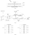
- Embodiment 1 illustrates a flow diagram of sending a CSI Reporting of a first node for an embodiment of the present application, as shown in FIG. 1 .
- the first node 100 receives the first CSI-ReportConfig and the first DCI in step 101 and, in step 102, sending at least a first CSI Reporting as a response to receiving the first DCI.
- the first CSI-ReportConfig is used to configure the at least first CSI Reporting; the first CSI Reporting occupies a CSI processing unit from the first symbol until the last symbol of the first physical layer channel, the first CSI Reporting is on the first physical layer channel; the first symbol is related to the reportConfigType domain in the first CSI-ReportConfig; when the reportConfigType domain in the first CSI-ReportConfig is semiPersistentOnPUSCH, the first symbol is the first symbol after the PDCCH occupied by the first DCI; when the reportConfigType domain in the first CSI-ReportConfig is periodic, the first symbol is the earliest symbol in the first occasion set, which includes at least one of the most recent CSI-RS occasion, the most recent CSI-IM occasion, or the most recent SSB occasion before the CSI reference resource of the first CSI Reporting.
- the first node 100 sends a first HARQ-ACK, wherein the first HARQ-ACK is associated to the first DCI; wherein after the first physical layer channel is in the first HARQ-ACK, the time domain resource occupied by the first HARQ-ACK is used to determine the first physical layer channel.
- the first CSI-ReportConfig is used to indicate the first occasion set.
- csi-IM-ResourcesForInterference in the first CSI-ReportConfig is used to configure the CSI-IM resources.
- the resourcesForChannelMeasurement in the first CSI-ReportConfig is used to configure a CSI-RS resource or an SSB resource.
- nzp-CSI-RS-ResourcesForInterference in the first CSI-ReportConfig is used to configure CSI-RS resources.
- the CSI-RS resources, CSI-IM resources, or SSB resources described above occupy multiple time slots in the time domain, where parts within one time slot are referred to as an occasion.
- the time intervals between any two adjacent time slots of the plurality of time slots are the same.
- the first symbol is the first symbol after the PDCCH occupied by the first DCI.
- the format of the first DCI is a DCI format for Uplink Grant.
- the format of the first DCI is Format 0_1.
- the format of the first DCI is Format 0_2.
- the symbol is an Orthogonal Frequency Division Multiplexing (OFDM) symbol.
- OFDM Orthogonal Frequency Division Multiplexing
- the symbol is a Discrete Fourier Transform-spread-OFDM (DFT-s-OFDM) symbol.
- DFT-s-OFDM Discrete Fourier Transform-spread-OFDM
- the first HARQ-ACK is associated with the first DCI comprising: The first HARQ-ACK is used to indicate whether the first DCI is correctly encoded.
- the first HARQ-ACK is associated with the first DCI comprising: The first HARQ-ACK is used to indicate whether the PDSCH scheduled by the first DCI is correctly encoded.
- the first HARQ-ACK includes a HARQ-ACK Codebook.
- the first HARQ-ACK includes a Type-1 HARQ-ACK Codebook.
- the first HARQ-ACK includes a Type-2 HARQ-ACK Codebook.
- the first HARQ-ACK includes a Type-3 HARQ-ACK Codebook.
- the first HARQ-ACK is one bit of a HARQ-ACK Codebook.
- the first DCI is transmitted on PDCCH.
- the first DCI occupies only one PDCCH candidate, the PDCCH occupied by the first DCI being a PDCCH candidate occupied by the first DCI.
- the first DCI occupies two PDCCH candidates, the first symbol after the PDCCH occupied by the first DCI being the first symbol after the latest symbol occupied by the two PDCCH candidates.
- the first CSI Reporting is calculated based on PDSCH on the CSI reference resource reported on the first CSI.
- the CSI reference resource reported by the first CSI is a subband or broadband for which the first CSI Reporting is directed in the frequency domain.
- the CSI reference resource reported by the first CSI belongs to the same Bandwidth Part (BWP) in the frequency domain as the frequency domain resource for which the first CSI is reported.
- BWP Bandwidth Part
- the CSI reference resource of the first CSI Reporting is located in a time slot over a time domain.
- the time slot of the CSI reference resource of the first CSI Reporting depends on the time slot occupied by the first physical layer channel.
- the time slot of the CSI reference resource of the first CSI Reporting is before the first physical layer channel.
- the first physical layer channel is PUSCH; and when the reportConfigType domain in the first CSI-ReportConfig is periodic, the first physical layer channel is PUCCH.
- the first physical layer channel is PUCCH.
- the first node 100 performs a measurement in a first RS resource group, the measurement in the first RS resource group being used to generate the first CSI Reporting; wherein the first DCI is used to trigger the measurement in the first RS resource group comprising at least one of a CSI-RS resource, a CSI-IM resource, and an SSB resource.
- the first DCI is used to trigger a first operation set.
- the first operation set includes performing measurements in the first RS resource group.
- the first operation set includes the at least first CSI Reporting.
- the first operation set includes switching a hypothetical for measuring the first RS resource group from a first Quasi co-location (QCL) parameter to a second QCL parameter.
- QCL Quasi co-location
- the first QCL parameter indicates at least one of the first downlink RS resource and the first qcl-Type (QCL type); the second QCL parameter indicates at least one of the second downlink RS resource and the second qcl-Type.
- the first and second downlink RS resources are respectively indicated by an SSB index.
- the first and second downlink RS resources are respectively a CSI-RS resource.
- any RS resource in the first RS resource group and the first downlink RS resource QCL before performing the behavior to switch from the first QCL parameter to the second QCL parameter, any RS resource in the first RS resource group and the second downlink RS resource QCL.
- any RS port of any one of the RS resources in the first RS resource group and any of the first downlink RS resources are QCL; after performing the behavior to switch from the first QCL parameter to the second QCL parameter, any of the RS resources in the first RS resource group and the second downlink RS resource are QCL.
- the QCL type of any one of the RS resources in the first RS resource group and the first downlink RS resource is indicated by the first qcl-Type ; after performing the behavior to switch from the first QCL parameter to the second QCL parameter, the QCL type of any one of the first RS resource groups and the second downlink RS resource is indicated by the second qcl-Type.
- the content included in each of the at least first CSI Reporting is indicated by the reportQuantity in the first CSI-reportconfig.
- any of the first CSI Reporting in the at least first CSI Reporting includes at least one of the following: Channel Quality Indicator (CQI), Precoding Matrix Indicator (PMI), CSI-RS resource indicator (CRI), SS/PBCH Block Resource Indicator (SSBRI), Layer Indicator (LI), Rank Indicator (RI), Layer 1 reference signal received power (L1-RSRP), Layer 1 signal-to-noise and interference ratio (L1-SINR), and Capability[Set]Index.
- CQI Channel Quality Indicator
- PMI Precoding Matrix Indicator
- CRI CSI-RS resource indicator
- SSBRI SS/PBCH Block Resource Indicator
- LI Layer Indicator
- RI Rank Indicator
- L1-RSRP Layer 1 reference signal received power
- L1-SINR Layer 1 signal-to-noise and interference ratio
- 5GS/EPS may be interconnected with other access networks, but these entities/interfaces are not shown for simplicity. As shown, 5GS/EPS provides packet exchange services. However, it will be readily understood by those skilled in the art that various concepts presented throughout the present application can be extended to a network or other cellular network providing circuit switching services.
- the RAN includes nodes 203 and other nodes 204.
- the node 203 provides for termination of the user and control plane protocol toward UE201.
- the nodes 203 may be connected to other nodes 204 via an Xn interface (e.g., backhaul)/X2 interface.
- the node 203 supports transmission over a Non-Terrestrial Network.
- the radio protocol architecture for the physical layer 351, the PDCP sublayer 354 in L2 layer 355, the RLC sublayer 353 in L2 layer 355, and the MAC sublayer 352 in L2 layer 355 is generally similar to the corresponding layers and sublayers in the control plane 300.
- the PDCP sublayer 354 also provides header compression for upper-layer data packets to reduce radio transmission overhead.
- the L2 layer 355 in the user plane 350 also comprises a sublayer 356 of Service Data Adaption Protocol (SDAP), which is responsible for mapping between the QoS stream and Data Radio Bearer (DRB) to support the diversity of the business.
- SDAP Service Data Adaption Protocol
- the wireless protocol architecture in FIG. 3 applies to the second node in the present application.
- the first DCI in the present application is generated at the PHY301.
- the at least first CSI Reporting in the present application is generated at the PHY301.
- the measurement for the first reference signal set in the present application is performed in the PHY301.
- Embodiment 4 illustrates a schematic diagram of a hardware module for a communication node according to an embodiment of the present application, as shown in FIG. 4.
- FIG. 4 is a block diagram of a first communication device 450 and a second communication device 410 in communication with each other over an access network.
- the second communication device 410 comprises a controller/processor 475, a memory 476, a receiving processor 470, a transmission processor 416, a multi-antenna receiving processor 472, a multi-antenna transmission processor 471, a transmitter/receiver 418, and an antenna 420.
- the upper data packet from the core network is provided to the controller/processor 475.
- the controller/processor 475 implements the functionality of the L2 layer.
- the controller/processor 475 provides header compression, encryption, packet segmentation and reordering, multiplexing between logic and the transport channel, and radio resource distribution to the first communication device 450 based on various priority measures.
- the controller/processor 475 is also responsible for the retransmission of the lost package and the signaling to the first communication device 450.
- the transmission processor 416 and the multi-antenna transmission processor 471 implement various signal processing functions for the L1 layer (i.e., the physical layer).
- the transmission processor 416 implements coding and interleaving to facilitate forward error correction (FEC) at the second communication device 410 and mapping of signal clusters based on various modulation schemes (e.g., Binary Phase Shift Keying (BPSK), Quadrature Phase Shift Keying (QPSK), M-Phase Shift Keying (M-PSK), and M-Quadrature Amplitude Modulation (M-QAM)).
- FEC forward error correction
- BPSK Binary Phase Shift Keying
- QPSK Quadrature Phase Shift Keying
- M-PSK M-Phase Shift Keying
- M-QAM M-Quadrature Amplitude Modulation
- the multi-antenna transmission processor 471 pre-codes encoded and modulated symbols in digital space, including codebook-based pre-coding and non-codebook-based pre-coding, and beam-based processing, generating one or more spatial streams.
- the transmission processor 416 maps each spatial stream to a sub-carrier, multiplexing with a reference signal (e.g., a frequency director) in the time and/or frequency domain, and then used an Inverse Fast Fourier Transform (IFFT) to generate a physical channel of the time domain multi-wave symbol stream on the carrier.
- IFFT Inverse Fast Fourier Transform
- the multi-antenna transmission processor 471 then sends the simulated pre-encoding/beaming operation for the time domain multi-carrier symbol flow.
- Each transmitter 418 converts the baseband multi-carrier symbol flow provided by the multi-antenna transmission processor 471 into a radio frequency flow, which is then provided to a different antenna 420.
- each receiver 454 receives a signal through its respective antenna 452. Each receiver 454 resumes information modulated onto the radio frequency carrier and provides a radio frequency flow to the receiving processor 456 into a base band multi carrier symbol flow.
- the receiving processor 456 and the multi-antenna receiving processor 458 implement various signal processing functions of the L1 layer.
- the multi-antenna receiving processor 458 performs a received analog pre-encoding/beam-engraving operation on the base band multi-carrier symbol flow from the receiver 454.
- the receiving processor 456 uses a Fast Fourier Transform (FFT) to convert the base band multi-carrier symbol flow from the time domain to the frequency domain after receiving the analog pre-encoding/beam-based manipulation.
- FFT Fast Fourier Transform
- the physical layer data signal and the reference signal are demultiplexed by the receiving processor 456, where the reference signal is used for channel estimation and the data signal recovers any spatial flow to the first communication device 450 for destination after multi-antenna detection by the multi-antenna receiving processor 458.
- the symbols on each spatial flow are demodulated and restored in the receiving processor 456 and generate a soft decision.
- the processor 456 is then decoded and de-interleaving the soft decision to restore the upper layer data and control signal transmitted by the second communication device 410 over the physical channel.
- the upper layer data and control signals are then provided to the controller/processor 459.
- the controller/processor 459 implements the functions of the L2 layer.
- the controller/processor 459 may be associated with a memory 460 storing program code and data.
- the memory 460 may be referred to as a computer-readable medium.
- the controller/processor 459 provides multiplexing between the transport and logical channel, packet reassembly, decryption, header decompression, control signal processing to recover the upper data packet from the core network.
- the upper data packet is then provided to all protocol layers above the L2 layer.
- Various control signals may also be provided to L3 for L3 processing.
- the data source 467 is used to provide the upper data packet to the controller/processor 459.
- the data source 467 represents all protocol layers above the L2 layer.
- the controller/processor 459 implements header compression, encryption, packet segmentation and reordering, and multiplexing between logic and transport channels based on wireless resource allocation, implementing L2 layer functions for the user plane and control plane.
- the controller/processor 459 is also responsible for the retransmission of the lost package and the signaling to the second communication device 410.
- the transmission processor 468 executes the modulation mapping, channel encoding, while the multi-antenna transmission processor 457 performs digital multi-antenna spatial pre-coding, including both codebook-based pre-coding and non-codebook-based pre-coding, and beam-based processing, and then the transmission processor 468 tailors the generated spatial stream to a multi-wave/single-wave symbol stream, which is provided to a different antenna 452 via the transmitter 454 after a simulated pre-encoded/beam operation in the multi-antenna transmission processor 457.
- Each transmitter 454 first converts the baseband symbol flow provided by the multi-antenna transmission processor 457 into a radio frequency symbol flow and then provides it to the antenna 452.
- the second communication device 410 performs functions similar to those of the receiving function at the first communication device 450, as described in the transmission from the second communication device 410 to the first communication device 450.
- Each receiver 418 receives a radio frequency signal through its respective antenna 420, converts the received radio frequency signal into a baseband signal, and provides the baseband signal to the multi-antenna receiving processor 472 and the receiving processor 470.
- the receiving processor 470 and the multi-antenna receiving processor 472 collectively implement the functions of the L1 layer.
- the controller/processor 475 implements L2 layer functions.
- the controller/processor 475 may be associated with memory 476 storing program code and data.
- the memory 476 may be referred to as a computer-readable medium.
- the controller/processor 475 In the transmission from the first communication device 450 to the second communication device 410, the controller/processor 475 provides multiplexing between the transport and logical channel, packet reassembly, decryption, header decompression, control signal processing to recover the upper data packet from the UE450.
- the upper data packet from the controller/processor 475 may be provided to the core network.
- the first communication device 450 comprises: at least one processor and at least one memory, and at least the one memory comprising computer program code; at least the one memory and the computer program code being configured to be used together with at least the one processor, the first communication device 450 apparatus at least: receiving a first CSI-ReportConfig and receive a first DCI; sending at least a first CSI Reporting as a response to receiving the first DCI; wherein the first CSI-ReportConfig is used to configure the at least first CSI Reporting; the first CSI Reporting occupies a CSI processing unit from the first symbol until the last symbol of the first physical layer channel, the first CSI Reporting is on the first physical layer channel; the first symbol is related to the reportConfigType domain in the first CSI-ReportConfig; when the reportConfigType domain in the first CSI-ReportConfig is semiPersistentOnPUSCH, the first symbol is the first symbol after the PDCCH occupied by the first DCI; when the reportConfigType domain in the first CSI-Re
- the first communication device 450 comprises: A memory storing a computer-readable instruction program that when executed by at least one processor generates an action, the action comprises: receiving a first CSI-ReportConfig and receive a first DCI; sending at least a first CSI Reporting as a response to receiving the first DCI; wherein the first CSI-ReportConfig is used to configure the at least first CSI Reporting; the first CSI Reporting occupies a CSI processing unit from the first symbol until the last symbol of the first physical layer channel, the first CSI Reporting is on the first physical layer channel; the first symbol is related to the reportConfigType domain in the first CSI-ReportConfig; when the reportConfigType domain in the first CSI-ReportConfig is semiPersistentOnPUSCH, the first symbol is the first symbol after the PDCCH occupied by the first DCI; when the reportConfigType domain in the first CSI-ReportConfig is periodic, the first symbol is the earliest symbol in the first occasion set, which includes at least
- the second communication device 410 includes: at least one processor and at least one memory, and at least the one memory comprising computer program code; at least the one memory and the computer program code being configured to be used together with at least the one processor.
- the second communication device 410 at least: sending a first CSI-ReportConfig and sending a first DCI; receiving at least a first CSI Reporting; wherein the first DCI is used to trigger the first CSI Reporting, the first CSI-ReportConfig is used to configure the at least first CSI Reporting; the first CSI Reporting occupies a CSI processing unit from the first symbol until the last symbol of the first physical layer channel, the first CSI Reporting is on the first physical layer channel; the first symbol is related to the reportConfigType domain in the first CSI-ReportConfig; when the reportConfigType domain in the first CSI-ReportConfig is semiPersistentOnPUSCH, the first symbol is the first symbol after the PDCCH occupied by the first DCI; when the reportConfigType domain
- At least one of the antenna 420, the transmitter 418, the transmission processor 416, the multi-antenna transmission processor 471, the controller/processor 475 is used to send a first DCI.
- the second communication device 410 is a base station device that supports a large latency difference.
- the second communication device 410 is a flight platform device.
- Embodiment 5 illustrates a signal transmission flow diagram according to an embodiment of the present application, as shown in FIG. 5 .
- the steps in block F0 and in block F1 are respectively optional in FIG. 5 .
- the first CSI-ReportConfig is used to configure the at least first CSI Reporting; the first CSI Reporting occupies a CSI processing unit from the first symbol until the last symbol of the first physical layer channel, the first CSI Reporting is on the first physical layer channel; the first symbol is related to the reportConfigType domain in the first CSI-ReportConfig; when the reportConfigType domain in the first CSI-ReportConfig is semiPersistentOnPUSCH, the first symbol is the first symbol after the PDCCH occupied by the first DCI; when the reportConfigType domain in the first CSI-ReportConfig is periodic, the first symbol is the earliest symbol in the first occasion set, which includes at least one of the most recent CSI-RS occasion, the most recent CSI-IM occasion, or the most recent SSB occasion before the CSI reference resource of the first CSI Reporting.
- the second node N2 receiving the first HARQ-ACK in the step S201; the first node N1, sending the first HARQ-ACK in the step S101, the first HARQ-ACK being associated to the first DCI; wherein after the first physical layer channel is at the first HARQ-ACK, the time domain resource occupied by the first HARQ-ACK is used to determine the first physical layer channel.
- the first DCI is used to indicate a TCI state of a CSI-RS resource in the first RS resource group.
- the first DCI is used to trigger a rate match for PDSCH execution on Resource Element (RE) of the first RS resource group.
- RE Resource Element
- the first DCI is used to indicate a time domain resource of the first RS resource group.
- the Time domain resource assignment (TDRA) domain in the first DCI is used to indicate the time domain resource occupied by the first physical layer channel.
- the PDSCH-to-HARQ_feedback timing indicator domain in the first DCI indicates the time domain resource occupied by the first HARQ-ACK.
- the time domain resources occupied by the first HARQ-ACK implicitly indicate time domain resources occupied by the first physical layer channel.
- the time slot used for CSI Reporting is indicated by the reportSlotConfig domain in the first CSI-ReportConfig.
- the block F0 is present.
- the first HARQ-ACK is received.
- the block F1 is present.
- the first node N1 performs measurements in the first RS resource group.
- the first node N1 does not perform measurements in the first RS resource group.
- the first HARQ-ACK is an ACK.
- the time domain resource occupied by the first HARQ-ACK is a time domain resource occupied by PUSCH carrying the first HARQ-ACK.
- the time domain resource occupied by the first HARQ-ACK is a time domain resource occupied by PUCCH carrying the first HARQ-ACK.
- the first HARQ-ACK is used to indicate whether the first DCI is properly encoded.
- the first HARQ-ACK is used to indicate whether the PDSCH scheduled by the first DCI is correctly encoded.
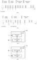
- Embodiment 6 illustrates a schematic diagram of a first PDCCH, a first occasion set, and a first physical layer channel, according to an embodiment of the present application, as shown in FIG. 6 .
- the horizontal axis represents the time
- the small box filled by slashes represents a CSI-RS occasion
- the small box filled by desk slashes represents a CSI-IM occasion
- the small box filled by crosslines represents a physical layer channel
- the small box filled by slashes represents a CSI reference resource.
- the first DCI is in the first PDCCH, and the time domain resources occupied by the first PDCCH are indicated by arrow a1; the signaling used to configure the time domain resources occupied by the physical layer channel in FIG. 6 includes the first CSI-ReportConfig; the first CSI Reporting is on the first physical layer channel, which occupies the time domain resources indicated by arrow j1; the time slot to which these time domain resources belong is used to determine the CSI reference resource of the first CSI Reporting; arrow k1 indicates the CSI reference resource of the first CSI Reporting; arrows h1 and i1 respectively indicate the most recent CSI-RS occasion and the most recent CSI-IM occasion before the CSI reference resource of the first CSI Reporting; the first occasion set includes the most recent CSI-RS occasion and the most recent CSI-IM occasion; the first symbol is related to the reportConfigType domain in the first CSI-ReportConfig; if the reportConfigType domain in the first CSI-ReportConfig is
- the time slot to which the first physical layer channel belongs is a time slotn'
- the CSI reference resource reported by the first CSI is a time slot f ( n ')on the time domain
- the f ( n ') is a function.
- the first DCI is used to indicate a time slotn'.
- the first DCI is used to indicate a symbol occupied by the first physical layer channel in a time slot n' .
- f ( n ') and n' can be referenced in Section 5.2.2.5 of 3GPP TS38.214.
- the time slot of the CSI reference resource of the first CSI Reporting is before the first physical layer channel.
- FIG. 6 does not limit the location and size of the time domain resources of the first PDCCH in the present application.
- FIG. 6 does not limit the location and size of the time domain resources of the CSI-RS occasion in the present application.
- FIG. 6 does not limit the location and size of the time domain resources of the CSI-IM occasion in the present application.
- FIG. 6 does not limit whether the time domain resources of the CSI-IM occasion in the present application are contiguous.
- the resource for measuring is used to transmit PDSCH before being activated.
- UE performs a rate match for the resource for measurement after the resource for measurement is activated.
- the CSI-RS occasion and CSI-IM occasion in the dashed line box c2 in FIG. 7 do not appear.
- the resource for measurement includes a CSI-IM resource.
- the time slot of the CSI reference resource of the first CSI Reporting depends on the time slot occupied by the first physical layer channel.
- the time slot to which the first physical layer channel belongs is a time slot n'
- the CSI reference resource reported by the first CSI is a time slot f ( n ')on the time domain
- the f ( n ') is a function.
- the first DCI is used to indicate a time slotn'.
- f ( n ') and n' can be referenced in Section 5.2.2.5 of 3GPP TS38.214.
- the physical layer channel in FIG. 7 is PUSCH.
- the physical layer channel in the FIG. 7 is PUCCH.
- the physical layer channel in FIG. 7 is PUCCH.
- Embodiment 8 illustrates a structural block diagram of a processing device for use in a first node according to an embodiment of the present application, as shown in FIG. 8 .
- the processing device 1600 in the first node includes a first receiver 1601 and a first emitter 1602. the first receiver 1601, receiving a first CSI-ReportConfig, receiving a first DCI;
- the first transmitter 1602 sending at least a first CSI Reporting as a response to receiving the first DCI.
- the first symbol is the first symbol after the PDCCH occupied by the first DCI.
- the at least first CSI Reporting comprises a plurality of CSI Reporting, with the first CSI Reporting being the earliest among them; for any CSI Reporting other than the first CSI Reporting, the CSI processing unit is occupied from the target symbol until the last symbol of the target physical layer channel, and the CSI Reporting is on the target physical layer channel; the target symbol is the earliest symbol in the target occasion set, which includes at least one of the most recent CSI-RS occasion, the most recent CSI-IM occasion, or the most recent SSB occasion before the CSI reference resource of the CSI Reporting.
- the first receiver 1601 includes an antenna 452, a receiver 454, and a receiving processor 456 in the FIG. 4 of the present application.
- the first transmitter 1602 includes an antenna 452, receiver 454, a multi-antenna receiving processor 458, a receiving processor 456, a controller/processor 459, a memory 460, and a data source 467 in FIG. 4 of the present application.
- the first transmitter 1602 includes an antenna 452, receiver 454, a multi-antenna receiving processor 458, and a receiving processor 456 in FIG. 4 of the present application.
- the first transmitter 1602 includes an antenna 452, a receiver 454, and a receiving processor 456 in FIG. 4 of the present application.
- the first transmitter 1602 includes an antenna 452, a transmitter 454, a multi-antenna transmission processor 457, and a transmission processor 468 in FIG. 4 of the present application..
- the second receiver 1702 receiving at least a first CSI Reporting.
- the second receiver 1702 receives a first HARQ-ACK, and the first HARQ-ACK being associated with the first DCI; the first physical layer channel follows the first HARQ-ACK, and the time domain resources occupied by the first HARQ-ACK are used to determine the first physical layer channel.
- the at least first CSI Reporting comprises a plurality of CSI Reporting, with the first CSI Reporting being the earliest among them; for any CSI Reporting other than the first CSI Reporting, the CSI processing unit is occupied from the target symbol until the last symbol of the target physical layer channel, and the CSI Reporting is on the target physical layer channel; the target symbol is the earliest symbol in the target occasion set, which includes at least one of the most recent CSI-RS occasion, the most recent CSI-IM occasion, or the most recent SSB occasion before the CSI reference resource of the CSI Reporting.
- the first physical layer channel is PUSCH; and when the reportConfigType domain in the first CSI-ReportConfig is periodic, the first physical layer channel is PUCCH.
- the second transmitter 1701 includes an antenna 420, a transmitter 418, a multi-antenna transmission processor 471 and a transmission processor 416 in FIG. 4 of the present application.
- the second transmitter 1701 includes an antenna 420, a transmitter 418, and a transmission processor 416 in FIG. 4 of the present application.
- the second receiver 1702 includes an antenna 420, a transmitter 418, a multi-antenna transmission processor 471, a transmission processor 416, a controller/processor 475, and a memory 476 in FIG. 4 of the present application.
- the second receiver 1702 includes an antenna 420, a transmitter 418, a multi-antenna transmission processor 471 and a transmission processor 416 in FIG. 4 of the present application.
- the second receiver 1702 includes an antenna 420, a transmitter 418, and a transmission processor 416 in FIG. 4 of the present application.
Landscapes
- Engineering & Computer Science (AREA)
- Signal Processing (AREA)
- Computer Networks & Wireless Communication (AREA)
- Mobile Radio Communication Systems (AREA)
Applications Claiming Priority (2)
| Application Number | Priority Date | Filing Date | Title |
|---|---|---|---|
| CN202210971801.7A CN117675135A (zh) | 2022-08-12 | 2022-08-12 | 用于无线通信的方法和装置 |
| PCT/CN2023/112780 WO2024032801A1 (zh) | 2022-08-12 | 2023-08-12 | 用于无线通信的方法和装置 |
Publications (1)
| Publication Number | Publication Date |
|---|---|
| EP4580106A1 true EP4580106A1 (de) | 2025-07-02 |
Family
ID=89851051
Family Applications (1)
| Application Number | Title | Priority Date | Filing Date |
|---|---|---|---|
| EP23852021.7A Pending EP4580106A1 (de) | 2022-08-12 | 2023-08-12 | Verfahren und vorrichtung zur drahtlosen kommunikation |
Country Status (5)
| Country | Link |
|---|---|
| US (1) | US20260089542A1 (de) |
| EP (1) | EP4580106A1 (de) |
| CN (1) | CN117675135A (de) |
| CO (1) | CO2025003187A2 (de) |
| WO (1) | WO2024032801A1 (de) |
Cited By (1)
| Publication number | Priority date | Publication date | Assignee | Title |
|---|---|---|---|---|
| WO2025251889A1 (zh) * | 2024-06-07 | 2025-12-11 | 荣耀终端股份有限公司 | 被用于无线通信的节点中的csi上报的方法和装置 |
Families Citing this family (2)
| Publication number | Priority date | Publication date | Assignee | Title |
|---|---|---|---|---|
| WO2025200856A1 (zh) * | 2024-03-25 | 2025-10-02 | 荣耀终端股份有限公司 | 一种被用于无线通信的节点中的与pdsch有关的方法和装置 |
| WO2026026673A1 (zh) * | 2024-07-31 | 2026-02-05 | 上海推络通信科技合伙企业(有限合伙) | 一种被用于无线通信中信道状态信息上报的方法和装置 |
Family Cites Families (4)
| Publication number | Priority date | Publication date | Assignee | Title |
|---|---|---|---|---|
| CN110971382B (zh) * | 2018-09-30 | 2023-04-07 | 维沃移动通信有限公司 | 一种确定信道状态信息csi处理单元占用时间的方法、终端设备 |
| KR102938954B1 (ko) * | 2019-08-13 | 2026-03-12 | 삼성전자주식회사 | 무선 통신 시스템에서 채널상태정보 보고 방법 및 장치 |
| CN113517967B (zh) * | 2020-04-11 | 2022-09-09 | 维沃移动通信有限公司 | 信道状态信息csi报告的确定方法和通信设备 |
| WO2022028491A1 (en) * | 2020-08-07 | 2022-02-10 | FG Innovation Company Limited | Apparatus and method for aperiodic channel state information transmission |
-
2022
- 2022-08-12 CN CN202210971801.7A patent/CN117675135A/zh active Pending
-
2023
- 2023-08-12 WO PCT/CN2023/112780 patent/WO2024032801A1/zh not_active Ceased
- 2023-08-12 US US19/480,788 patent/US20260089542A1/en active Pending
- 2023-08-12 EP EP23852021.7A patent/EP4580106A1/de active Pending
-
2025
- 2025-03-12 CO CONC2025/0003187A patent/CO2025003187A2/es unknown
Cited By (1)
| Publication number | Priority date | Publication date | Assignee | Title |
|---|---|---|---|---|
| WO2025251889A1 (zh) * | 2024-06-07 | 2025-12-11 | 荣耀终端股份有限公司 | 被用于无线通信的节点中的csi上报的方法和装置 |
Also Published As
| Publication number | Publication date |
|---|---|
| US20260089542A1 (en) | 2026-03-26 |
| WO2024032801A1 (zh) | 2024-02-15 |
| CN117675135A (zh) | 2024-03-08 |
| CO2025003187A2 (es) | 2025-07-28 |
Similar Documents
| Publication | Publication Date | Title |
|---|---|---|
| EP4580106A1 (de) | Verfahren und vorrichtung zur drahtlosen kommunikation | |
| WO2019170057A1 (zh) | 一种被用于无线通信的用户设备、基站中的方法和装置 | |
| CN110290551B (zh) | 一种被用于无线通信的用户设备、基站中的方法和装置 | |
| CN112333776B (zh) | 一种被用于无线通信的节点中的方法和装置 | |
| CN113453353B (zh) | 一种被用于无线通信的节点中的方法和装置 | |
| WO2021036790A1 (zh) | 一种被用于无线通信的节点中的方法和装置 | |
| US20210352681A1 (en) | Method and device in a node used for wireless communication | |
| WO2023088128A1 (zh) | 一种被用于无线通信的节点中的方法和装置 | |
| WO2022188749A1 (zh) | 一种被用于无线通信的节点中的方法和装置 | |
| EP4583443A1 (de) | Verfahren zur verwendung in einem knoten zur drahtlosen kommunikation und vorrichtung | |
| CN112423389A (zh) | 一种被用于无线通信的节点中的方法和装置 | |
| WO2023083236A1 (zh) | 用于无线通信的方法和装置 | |
| WO2023061352A1 (zh) | 一种被用于无线通信的节点中的方法和装置 | |
| WO2026081594A1 (zh) | 一种被用于无线通信的节点中的方法和装置 | |
| WO2025251887A1 (zh) | 用于无线通信的节点中的与pucch有关的方法和装置 | |
| EP4580103A1 (de) | Verfahren und vorrichtung zur verwendung in einem drahtloskommunikationsknoten | |
| EP4583604A1 (de) | Verfahren und vorrichtung zur drahtlosen kommunikation | |
| CN115348676A (zh) | 一种被用于无线通信的节点中的方法和装置 | |
| EP4576631A1 (de) | Verfahren und vorrichtung zur drahtlosen kommunikation | |
| EP4686302A1 (de) | Verfahren und vorrichtung zur drahtlosen kommunikation | |
| EP4618461A1 (de) | Verfahren und vorrichtung zur drahtlosen kommunikation | |
| CN115715014A (zh) | 一种被用于无线通信的节点中的方法和装置 | |
| CN115119323A (zh) | 一种被用于无线通信的节点中的方法和装置 | |
| EP4568326A1 (de) | Verfahren und vorrichtung zur drahtlosen kommunikation | |
| EP4525341A1 (de) | Verfahren und vorrichtung zur drahtlosen kommunikation |
Legal Events
| Date | Code | Title | Description |
|---|---|---|---|
| STAA | Information on the status of an ep patent application or granted ep patent |
Free format text: STATUS: THE INTERNATIONAL PUBLICATION HAS BEEN MADE |
|
| PUAI | Public reference made under article 153(3) epc to a published international application that has entered the european phase |
Free format text: ORIGINAL CODE: 0009012 |
|
| STAA | Information on the status of an ep patent application or granted ep patent |
Free format text: STATUS: REQUEST FOR EXAMINATION WAS MADE |
|
| 17P | Request for examination filed |
Effective date: 20250312 |
|
| AK | Designated contracting states |
Kind code of ref document: A1 Designated state(s): AL AT BE BG CH CY CZ DE DK EE ES FI FR GB GR HR HU IE IS IT LI LT LU LV MC ME MK MT NL NO PL PT RO RS SE SI SK SM TR |
|
| RAP1 | Party data changed (applicant data changed or rights of an application transferred) |
Owner name: APOGEE NETWORKS, LLC |
|
| DAV | Request for validation of the european patent (deleted) | ||
| DAX | Request for extension of the european patent (deleted) |