EP4581987A1 - Coulisseau pour rideau - Google Patents
Coulisseau pour rideau Download PDFInfo
- Publication number
- EP4581987A1 EP4581987A1 EP24158705.4A EP24158705A EP4581987A1 EP 4581987 A1 EP4581987 A1 EP 4581987A1 EP 24158705 A EP24158705 A EP 24158705A EP 4581987 A1 EP4581987 A1 EP 4581987A1
- Authority
- EP
- European Patent Office
- Prior art keywords
- section
- rail
- shaped
- area
- guide slot
- Prior art date
- Legal status (The legal status is an assumption and is not a legal conclusion. Google has not performed a legal analysis and makes no representation as to the accuracy of the status listed.)
- Pending
Links
Images


Classifications
-
- A—HUMAN NECESSITIES
- A47—FURNITURE; DOMESTIC ARTICLES OR APPLIANCES; COFFEE MILLS; SPICE MILLS; SUCTION CLEANERS IN GENERAL
- A47H—FURNISHINGS FOR WINDOWS OR DOORS
- A47H15/00—Runners or gliders for supporting curtains on rails or rods
- A47H15/04—Gliders
-
- A—HUMAN NECESSITIES
- A47—FURNITURE; DOMESTIC ARTICLES OR APPLIANCES; COFFEE MILLS; SPICE MILLS; SUCTION CLEANERS IN GENERAL
- A47H—FURNISHINGS FOR WINDOWS OR DOORS
- A47H1/00—Curtain suspension devices
- A47H1/04—Curtain rails
- A47H2001/042—Curtain rails shaped as curtain rods
Definitions
- the invention relates to a glider for hanging curtains or the like on a rail and to a method for producing the glider according to the preamble of the independent claims.
- a curtain glider with a head section is shown that can be inserted into the curtain rail by means of a plug-and-twist movement.
- the guide section must be compressible and springy so that it can be compressed when the curtain glider is inserted into the rail's receiving slot. Due to its design, such a curtain glider does not provide a secure hold in the curtain rail and is difficult to handle.
- a T-shaped head area means a head area that essentially has a T-shaped geometry, but can also contain elements that differ from the T-shape. differ, but the overall appearance still shows a T.
- the hanging area here is designed for hanging curtains in the form of an eyelet, a hook or the like, but can also serve as a handle area to insert the glider into the rail.
- the length and width of the central axis of the neck area can be easily varied during the manufacturing process.
- a C-shaped rail means a rail that essentially has a C-shaped cross-section, but can also be rounder or more angular than a C or can have a larger or smaller distance between the two supporting shoulders, but the overall appearance still shows a C.
- One-piece here means that the glider consists of one part or one casting and is not assembled from two or more parts.
- both legs of the T-shaped head region have a narrow first section and a wider second section in a longitudinal view.
- the longitudinal view corresponds to the view when both legs of the T-shaped head area are arranged orthogonally to the guide slot of the rail.
- a first narrow section is advantageous for easy insertion of the glider into the rail, while a wider second section leads to a high load-bearing capacity after the glider has been successfully inserted and prevents the suspended curtain from falling down.
- a solid-state joint is arranged between the narrow first section and the wider second section.
- a flexure joint is a region of a component, in this case the slider, which allows relative movement between two rigid body regions, in this case the narrow first section and the wider second section, by bending.
- the solid-state joint has greater mobility in the direction of the suspension area than in the direction of the narrow first section.
- the advantage is that the glider can be easily inserted into any position on the rail due to the greater mobility of the solid-state joint in the direction of the suspension area, but due to the reduced mobility in the direction of the narrow first section, it cannot be removed from the rail again despite an applied force such as the load-bearing capacity of the curtain caused by gravity, and thus offers a secure hold for a curtain and enables simple and easy movement of the curtains.
- the narrow first section is spaced further away from the suspension area than the wider second section.
- the narrow first section can be easily inserted into the rail at any position.
- the wider second section ensures that the glider remains in the rail, even when an applied force, such as the weight of the curtain caused by gravity, pulls on the glider. This guarantees a secure hold of the curtain.
- the narrow first section of the T-shaped head region is designed such that it can be inserted into the guide slot of the C-shaped rail at any position.
- the narrow first section is at most as wide as the guide slot in the longitudinal view.
- the advantage is that the slider can be inserted into the rail without requiring a special insertion opening or requiring the slider to be inserted in a specific position, thus offering a certain degree of flexibility when inserting the slider into the rail. This also ensures precise centering of the slider in the rail, facilitating the sliding movement.
- the wider second portion is wider than the guide slot in the longitudinal view.
- the wider second section of the T-shaped head region is formed in the form of two wings.
- the advantage of the wider second section being designed in the form of two wings is that the wings make it easier to insert the glider into the rail by folding the wings in.
- the two wings are designed to be snap-fitted behind the support shoulders when the T-shaped head region is inserted into the C-shaped rail, and the wider second section of the T-shaped head region can be arranged on the support shoulders.
- snap-in design means that when the glider is inserted, the wings fold into the guide slot of the rail with the help of a pressure movement and then fold out again automatically within the rail.
- the T-shaped head region is so wide at the narrow first section that, when the longitudinal view of the T-shaped head region is aligned parallel to the guide slot of the C-shaped rail, it can only be removed from the guide slot by means of a tilting movement.
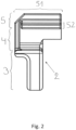
- the hanging area which can also be used as a grip area, as already described above, is grasped and pushed towards the shorter side of the L-shaped side view.
- the rotation-tilting movement comprises a 90° rotation of the slider from a sliding position to a removal position and a tilting movement to remove the slider.
- the advantage of this design is that the slider can be easily removed at any position on the splint. This can be accomplished from the wrist, without the user having to grasp it again.
- the object is further achieved by a method for producing a device for hanging curtains by means of an injection molding process with a device as described above.
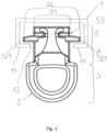
- the device 2 shown in longitudinal view and here in the form of a glider, is used to hang curtains or the like on a rail 1.
- the rail 1 is C-shaped in cross-section and has two supporting shoulders 11 and a guide slot 12 flanked by the two supporting shoulders 11.
- the glider 2 comprises three areas.
- the first area is a hanging area 3, which is shown here in the form of an eyelet that can accommodate a hook to which, for example, a curtain is attached.
- the hanging area 3 also serves as a handle area for the user to grasp the glider for insertion into the rail.
- the head area 5 is used to attach the glider 2 to the rail 1 and is essentially T-shaped in the longitudinal view.
- the two legs of the T-shaped head area 5 are divided into a narrower first section 51 and a wider second section 52, which are arranged one above the other.
- the narrower first section 51 is inserted into the guide slot 12 at any position when inserting the slider 2.
- the wider second section 52 comprises two wings 521. Between the narrower first section 51 and the wider A solid-state joint 53 is arranged in the second section 52.
- the solid-state joint 53 serves to limit the mobility of the wings 521 towards the T-shaped head area 5 such that the slider 2 remains in the rail 1, even when the suspension area 3 is pulled with great force.
- the third and final area is the neck area 4, which connects the T-shaped head area 5 and the suspension area 3.
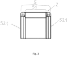
- Figure 3 shows the Figure 1 shown slider 2 in a plan view. Both the narrow first region 51 of the T-shaped head region 5 and the two wings 521 of the wider second region 52 are shown.
- the narrow first region 51 shows a shorter and a wider side.
- the shorter side corresponds to the width of the guide slot 12 of the rail 1 (not shown here, see Fig. 1 ) and is aligned orthogonally to the guide slot in the use position.
- the wider side is slightly wider than the width of the guide slot 12 of the rail 1 and is aligned parallel to the guide slot 12 in the use position. In the removal position, the wider side of the narrow first area 51 is orthogonal to the Guide slot and can therefore only be removed by tilting the rail 1.
Landscapes
- Curtains And Furnishings For Windows Or Doors (AREA)
Applications Claiming Priority (1)
| Application Number | Priority Date | Filing Date | Title |
|---|---|---|---|
| EP24150779 | 2024-01-08 |
Publications (1)
| Publication Number | Publication Date |
|---|---|
| EP4581987A1 true EP4581987A1 (fr) | 2025-07-09 |
Family
ID=89535998
Family Applications (1)
| Application Number | Title | Priority Date | Filing Date |
|---|---|---|---|
| EP24158705.4A Pending EP4581987A1 (fr) | 2024-01-08 | 2024-02-20 | Coulisseau pour rideau |
Country Status (1)
| Country | Link |
|---|---|
| EP (1) | EP4581987A1 (fr) |
Citations (3)
| Publication number | Priority date | Publication date | Assignee | Title |
|---|---|---|---|---|
| CH559027A5 (en) * | 1971-12-13 | 1975-02-28 | Jenny Hans | Slider for C-shaped curtain rails - has short slider head with two flanges and curtain fastening eyelet inserted in rail groove |
| DE202011004238U1 (de) * | 2010-05-27 | 2011-05-26 | MHZ Hachtel GmbH & Co. KG, 70771 | Gardinengleiter |
| DE202011000065U1 (de) | 2011-01-12 | 2012-04-17 | Nodeko Gmbh | Vorrichtung zum Aufhängen einer Gardine oder dergleichen |
-
2024
- 2024-02-20 EP EP24158705.4A patent/EP4581987A1/fr active Pending
Patent Citations (4)
| Publication number | Priority date | Publication date | Assignee | Title |
|---|---|---|---|---|
| CH559027A5 (en) * | 1971-12-13 | 1975-02-28 | Jenny Hans | Slider for C-shaped curtain rails - has short slider head with two flanges and curtain fastening eyelet inserted in rail groove |
| DE202011004238U1 (de) * | 2010-05-27 | 2011-05-26 | MHZ Hachtel GmbH & Co. KG, 70771 | Gardinengleiter |
| DE102010021773A1 (de) | 2010-05-27 | 2011-12-01 | Mhz Hachtel Gmbh & Co. Kg | Gardinengleiter |
| DE202011000065U1 (de) | 2011-01-12 | 2012-04-17 | Nodeko Gmbh | Vorrichtung zum Aufhängen einer Gardine oder dergleichen |
Similar Documents
| Publication | Publication Date | Title |
|---|---|---|
| EP3760076B1 (fr) | Set de tiroir comprenant trois cotés différents | |
| DE3214727C2 (fr) | ||
| DE3687293T2 (de) | Vollstaendig gegliederte lagerungsvorrichtung. | |
| DE3035218A1 (de) | Vorrichtung zum befestigen eines vorhangstangenhalters an einem wandbrett o.dgl. | |
| EP3909477A1 (fr) | Attache rideau | |
| EP2110498A1 (fr) | Système de corps de butée et corps de butée pour coffrages | |
| DE3884247T2 (de) | Verfahren zur Befestigung von grossen Spiegeln und Rahmenprofile dafür. | |
| EP3742931B1 (fr) | Glissière de guidage pour un tiroir et procédé pour aligner un tiroir à une glissière de guidage | |
| WO1994024912A1 (fr) | Element de suspension de rideaux a corps coulissant | |
| EP3712354A1 (fr) | Plateforme de coffrage | |
| DE1192379B (de) | Verbindungsstueck zum Aufbau von Gestellen aus Rohren | |
| EP4581987A1 (fr) | Coulisseau pour rideau | |
| DE102007014263B3 (de) | Verbindungsknoten für ein zwei- oder dreimensionales Tragwerk | |
| DE202011000065U1 (de) | Vorrichtung zum Aufhängen einer Gardine oder dergleichen | |
| DE19531658B4 (de) | Stützvorrichtung für eine Kabelbahn | |
| DE4006110C2 (fr) | ||
| DE19508378C1 (de) | Gardinengleiter | |
| AT401186B (de) | Dachleitungshalter, der zur auflage auf einen firstziegel bestimmt ist | |
| DE102013111085A1 (de) | Gardineneinführhilfe | |
| CH681852A5 (en) | One piece curtain fitment for slide rail of C-shaped cross-section - has head fitting into slide-rail which has lengthwise slot with side walls and slot flanges | |
| EP0213236A2 (fr) | Dispositif de type rayonnage | |
| DE3003363C2 (de) | Tragflügelbefestigung für Modellflugzeuge | |
| AT410169B (de) | Gardinengleiter | |
| DE3911843C2 (fr) | ||
| DE29604182U1 (de) | Vorrichtung zum Auf- bzw. Abhängen von Vorhängen |
Legal Events
| Date | Code | Title | Description |
|---|---|---|---|
| PUAI | Public reference made under article 153(3) epc to a published international application that has entered the european phase |
Free format text: ORIGINAL CODE: 0009012 |
|
| STAA | Information on the status of an ep patent application or granted ep patent |
Free format text: STATUS: THE APPLICATION HAS BEEN PUBLISHED |
|
| AK | Designated contracting states |
Kind code of ref document: A1 Designated state(s): AL AT BE BG CH CY CZ DE DK EE ES FI FR GB GR HR HU IE IS IT LI LT LU LV MC ME MK MT NL NO PL PT RO RS SE SI SK SM TR |
|
| STAA | Information on the status of an ep patent application or granted ep patent |
Free format text: STATUS: REQUEST FOR EXAMINATION WAS MADE |
|
| 17P | Request for examination filed |
Effective date: 20251023 |