EP4582199A1 - Outil revêtu - Google Patents
Outil revêtu Download PDFInfo
- Publication number
- EP4582199A1 EP4582199A1 EP23860069.6A EP23860069A EP4582199A1 EP 4582199 A1 EP4582199 A1 EP 4582199A1 EP 23860069 A EP23860069 A EP 23860069A EP 4582199 A1 EP4582199 A1 EP 4582199A1
- Authority
- EP
- European Patent Office
- Prior art keywords
- layer
- atom
- less
- hard coating
- tool
- Prior art date
- Legal status (The legal status is an assumption and is not a legal conclusion. Google has not performed a legal analysis and makes no representation as to the accuracy of the status listed.)
- Pending
Links
Images



Classifications
-
- C—CHEMISTRY; METALLURGY
- C23—COATING METALLIC MATERIAL; COATING MATERIAL WITH METALLIC MATERIAL; CHEMICAL SURFACE TREATMENT; DIFFUSION TREATMENT OF METALLIC MATERIAL; COATING BY VACUUM EVAPORATION, BY SPUTTERING, BY ION IMPLANTATION OR BY CHEMICAL VAPOUR DEPOSITION, IN GENERAL; INHIBITING CORROSION OF METALLIC MATERIAL OR INCRUSTATION IN GENERAL
- C23C—COATING METALLIC MATERIAL; COATING MATERIAL WITH METALLIC MATERIAL; SURFACE TREATMENT OF METALLIC MATERIAL BY DIFFUSION INTO THE SURFACE, BY CHEMICAL CONVERSION OR SUBSTITUTION; COATING BY VACUUM EVAPORATION, BY SPUTTERING, BY ION IMPLANTATION OR BY CHEMICAL VAPOUR DEPOSITION, IN GENERAL
- C23C14/00—Coating by vacuum evaporation, by sputtering or by ion implantation of the coating forming material
- C23C14/06—Coating by vacuum evaporation, by sputtering or by ion implantation of the coating forming material characterised by the coating material
- C23C14/0641—Nitrides
-
- C—CHEMISTRY; METALLURGY
- C23—COATING METALLIC MATERIAL; COATING MATERIAL WITH METALLIC MATERIAL; CHEMICAL SURFACE TREATMENT; DIFFUSION TREATMENT OF METALLIC MATERIAL; COATING BY VACUUM EVAPORATION, BY SPUTTERING, BY ION IMPLANTATION OR BY CHEMICAL VAPOUR DEPOSITION, IN GENERAL; INHIBITING CORROSION OF METALLIC MATERIAL OR INCRUSTATION IN GENERAL
- C23C—COATING METALLIC MATERIAL; COATING MATERIAL WITH METALLIC MATERIAL; SURFACE TREATMENT OF METALLIC MATERIAL BY DIFFUSION INTO THE SURFACE, BY CHEMICAL CONVERSION OR SUBSTITUTION; COATING BY VACUUM EVAPORATION, BY SPUTTERING, BY ION IMPLANTATION OR BY CHEMICAL VAPOUR DEPOSITION, IN GENERAL
- C23C14/00—Coating by vacuum evaporation, by sputtering or by ion implantation of the coating forming material
- C23C14/0021—Reactive sputtering or evaporation
- C23C14/0036—Reactive sputtering
-
- C—CHEMISTRY; METALLURGY
- C23—COATING METALLIC MATERIAL; COATING MATERIAL WITH METALLIC MATERIAL; CHEMICAL SURFACE TREATMENT; DIFFUSION TREATMENT OF METALLIC MATERIAL; COATING BY VACUUM EVAPORATION, BY SPUTTERING, BY ION IMPLANTATION OR BY CHEMICAL VAPOUR DEPOSITION, IN GENERAL; INHIBITING CORROSION OF METALLIC MATERIAL OR INCRUSTATION IN GENERAL
- C23C—COATING METALLIC MATERIAL; COATING MATERIAL WITH METALLIC MATERIAL; SURFACE TREATMENT OF METALLIC MATERIAL BY DIFFUSION INTO THE SURFACE, BY CHEMICAL CONVERSION OR SUBSTITUTION; COATING BY VACUUM EVAPORATION, BY SPUTTERING, BY ION IMPLANTATION OR BY CHEMICAL VAPOUR DEPOSITION, IN GENERAL
- C23C14/00—Coating by vacuum evaporation, by sputtering or by ion implantation of the coating forming material
- C23C14/22—Coating by vacuum evaporation, by sputtering or by ion implantation of the coating forming material characterised by the process of coating
- C23C14/34—Sputtering
- C23C14/3485—Sputtering using pulsed power to the target
-
- C—CHEMISTRY; METALLURGY
- C23—COATING METALLIC MATERIAL; COATING MATERIAL WITH METALLIC MATERIAL; CHEMICAL SURFACE TREATMENT; DIFFUSION TREATMENT OF METALLIC MATERIAL; COATING BY VACUUM EVAPORATION, BY SPUTTERING, BY ION IMPLANTATION OR BY CHEMICAL VAPOUR DEPOSITION, IN GENERAL; INHIBITING CORROSION OF METALLIC MATERIAL OR INCRUSTATION IN GENERAL
- C23C—COATING METALLIC MATERIAL; COATING MATERIAL WITH METALLIC MATERIAL; SURFACE TREATMENT OF METALLIC MATERIAL BY DIFFUSION INTO THE SURFACE, BY CHEMICAL CONVERSION OR SUBSTITUTION; COATING BY VACUUM EVAPORATION, BY SPUTTERING, BY ION IMPLANTATION OR BY CHEMICAL VAPOUR DEPOSITION, IN GENERAL
- C23C14/00—Coating by vacuum evaporation, by sputtering or by ion implantation of the coating forming material
- C23C14/22—Coating by vacuum evaporation, by sputtering or by ion implantation of the coating forming material characterised by the process of coating
- C23C14/34—Sputtering
- C23C14/3492—Variation of parameters during sputtering
-
- C—CHEMISTRY; METALLURGY
- C23—COATING METALLIC MATERIAL; COATING MATERIAL WITH METALLIC MATERIAL; CHEMICAL SURFACE TREATMENT; DIFFUSION TREATMENT OF METALLIC MATERIAL; COATING BY VACUUM EVAPORATION, BY SPUTTERING, BY ION IMPLANTATION OR BY CHEMICAL VAPOUR DEPOSITION, IN GENERAL; INHIBITING CORROSION OF METALLIC MATERIAL OR INCRUSTATION IN GENERAL
- C23C—COATING METALLIC MATERIAL; COATING MATERIAL WITH METALLIC MATERIAL; SURFACE TREATMENT OF METALLIC MATERIAL BY DIFFUSION INTO THE SURFACE, BY CHEMICAL CONVERSION OR SUBSTITUTION; COATING BY VACUUM EVAPORATION, BY SPUTTERING, BY ION IMPLANTATION OR BY CHEMICAL VAPOUR DEPOSITION, IN GENERAL
- C23C28/00—Coating for obtaining at least two superposed coatings either by methods not provided for in a single one of groups C23C2/00 - C23C26/00 or by combinations of methods provided for in subclasses C23C and C25C or C25D
- C23C28/04—Coating for obtaining at least two superposed coatings either by methods not provided for in a single one of groups C23C2/00 - C23C26/00 or by combinations of methods provided for in subclasses C23C and C25C or C25D only coatings of inorganic non-metallic material
- C23C28/044—Coating for obtaining at least two superposed coatings either by methods not provided for in a single one of groups C23C2/00 - C23C26/00 or by combinations of methods provided for in subclasses C23C and C25C or C25D only coatings of inorganic non-metallic material coatings specially adapted for cutting tools or wear applications
-
- C—CHEMISTRY; METALLURGY
- C23—COATING METALLIC MATERIAL; COATING MATERIAL WITH METALLIC MATERIAL; CHEMICAL SURFACE TREATMENT; DIFFUSION TREATMENT OF METALLIC MATERIAL; COATING BY VACUUM EVAPORATION, BY SPUTTERING, BY ION IMPLANTATION OR BY CHEMICAL VAPOUR DEPOSITION, IN GENERAL; INHIBITING CORROSION OF METALLIC MATERIAL OR INCRUSTATION IN GENERAL
- C23C—COATING METALLIC MATERIAL; COATING MATERIAL WITH METALLIC MATERIAL; SURFACE TREATMENT OF METALLIC MATERIAL BY DIFFUSION INTO THE SURFACE, BY CHEMICAL CONVERSION OR SUBSTITUTION; COATING BY VACUUM EVAPORATION, BY SPUTTERING, BY ION IMPLANTATION OR BY CHEMICAL VAPOUR DEPOSITION, IN GENERAL
- C23C28/00—Coating for obtaining at least two superposed coatings either by methods not provided for in a single one of groups C23C2/00 - C23C26/00 or by combinations of methods provided for in subclasses C23C and C25C or C25D
- C23C28/40—Coatings including alternating layers following a pattern, a periodic or defined repetition
- C23C28/42—Coatings including alternating layers following a pattern, a periodic or defined repetition characterized by the composition of the alternating layers
-
- C—CHEMISTRY; METALLURGY
- C23—COATING METALLIC MATERIAL; COATING MATERIAL WITH METALLIC MATERIAL; CHEMICAL SURFACE TREATMENT; DIFFUSION TREATMENT OF METALLIC MATERIAL; COATING BY VACUUM EVAPORATION, BY SPUTTERING, BY ION IMPLANTATION OR BY CHEMICAL VAPOUR DEPOSITION, IN GENERAL; INHIBITING CORROSION OF METALLIC MATERIAL OR INCRUSTATION IN GENERAL
- C23C—COATING METALLIC MATERIAL; COATING MATERIAL WITH METALLIC MATERIAL; SURFACE TREATMENT OF METALLIC MATERIAL BY DIFFUSION INTO THE SURFACE, BY CHEMICAL CONVERSION OR SUBSTITUTION; COATING BY VACUUM EVAPORATION, BY SPUTTERING, BY ION IMPLANTATION OR BY CHEMICAL VAPOUR DEPOSITION, IN GENERAL
- C23C30/00—Coating with metallic material characterised only by the composition of the metallic material, i.e. not characterised by the coating process
- C23C30/005—Coating with metallic material characterised only by the composition of the metallic material, i.e. not characterised by the coating process on hard metal substrates
Definitions
- An AlCr nitride is a film type having excellent wear resistance and heat resistance, and is widely applied to coated molds or coated cutting tools.
- coated tools coated with an Al-rich AlCr nitride having an Al content ratio of more than 70 atom% using an arc ion plating method have started to be proposed (Patent Documents 1 to 3).
- the number of droplets can be reduced by using a sputtering method in the formation of a hard coating.
- wear resistance may be inferior to that of a hard coating formed using the arc ion plating method.
- the present invention has been made in view of the above-described circumstances, and an object of the present invention is to provide a coated tool that realizes durability equal to or higher than in the case of using an arc ion plating method while reducing the number of droplets through the application of a sputtering method, for an Al-rich AlCr nitride or carbonitride.
- a coated tool is a coated tool including a substrate and a hard coating on the substrate, in which the hard coating includes an A layer provided on the substrate and a B layer provided on the A layer, the A layer is a nitride or a carbonitride containing 50 atom% or more and 70 atom% or less of Al and 30 atom% or more and 50 atom% or less of Cr with respect to a total amount of metal elements including metalloid elements, the B layer is a nitride or a carbonitride containing 70 atom% or more and 85 atom% or less of Al and 15 atom% or more and 30 atom% or less of Cr with respect to a total amount of metal elements including metalloid elements, the B layer is finer than the A layer, in the B layer, streaky phases having different brightnesses are confirmed in observation with a transmission electron microscope, the phases having different brightnesses have a region having a relatively high Al content and a region having a relatively low Al content, and the A layer and
- the present inventors have confirmed that durability of a coated tool is excellent for a sputtered coating for an Al-rich AlCr nitride or carbonitride having a specific microstructure.
- durability of a coated tool is excellent for a sputtered coating for an Al-rich AlCr nitride or carbonitride having a specific microstructure.
- the A layer consists of columnar crystals.
- the crystal structure of the A layer consists of cubic crystals.
- the columnar crystal of the A layer extends along a film thickness direction of the hard coating.
- the A layer provided on the substrate consists of columnar crystals, whereby the adhesion is improved.
- the average crystal grain size of the A layer is preferably 120 nm or more and 300 nm or less. That is, the average width of the columnar crystals of the A layer is preferably 120 nm or more and 300 nm or less.
- the average crystal grain size of the A layer or the average width of the columnar crystals can be acquired from a cross-sectional observation image obtained using a transmission electron microscope.
- the width of the columnar crystal of the A layer is the length of the columnar crystal in a direction orthogonal to a direction in which the columnar crystal extends (substantially the film thickness direction).
- the average width of the columnar crystals is calculated using a width measured in a central portion of the hard coating in the film thickness direction.
- the central portion in the film thickness direction refers to a portion in a range of 10% or less on both sides in the film thickness direction from the center of the hard coating in the film thickness direction.
- the central portion of the A layer in the film thickness direction is a portion in a range of 10% or less of the film thickness of the A layer on both sides in the film thickness direction from the center of the A layer in the film thickness direction.
- the average width of the columnar crystals is calculated as an average value of widths of 10 or more columnar crystals confirmed by the cross-sectional observation image.
- the film thickness of the A layer is preferably 0.3 ⁇ m or more and 3 ⁇ m or less.
- the A layer may contain metal elements other than Al and Cr.
- the A layer can also contain one element or two or more elements selected from elements of Groups 4a, 5a, and 6a of the periodic table and Si, B, Y, Yb, and Cu. These elements are generally contained to improve coating properties of the coated tool, and can be added within a range that does not significantly deteriorate the durability of the coated tool.
- the content ratios of the metal elements other than Al and Cr are too large, the durability of the coated tool may be deteriorated.
- the total content ratio thereof is preferably 10 atom% or less, more preferably 5 atom% or less.
- the B layer is provided on the A layer.
- the B layer is a nitride or a carbonitride containing 70 atom% or more and 85 atom% or less of Al and 15 atom% or more and 30 atom% or less of Cr with respect to the total amount of metal elements.
- the Al content ratio is 70 atom% or more.
- the Al content ratio is preferably 75 atom% or more.
- the toughness of the hard coating is significantly reduced.
- the Al content ratio is set to 90 atom% or less. Furthermore, in the B layer, the Al content ratio is preferably 85 atom% or less.
- the Cr content ratio is set to 10 atom% or more. Accordingly, a uniform and dense oxidation protection film is easily formed on the tool surface during processing, and damage to the tool is easily suppressed. Furthermore, in the B layer, the Cr content ratio is preferably set to 15 atom% or more. On the other hand, when the Cr content ratio is too large, the Al content ratio is relatively low, and it is difficult to obtain an effect of increasing the Al content ratio. Therefore, in the B layer, the Cr content ratio is set to 30 atom% or less. Furthermore, in the B layer, the Cr content ratio is preferably 25 atom% or less.
- the B layer may contain metal elements other than Al and Cr.
- the B layer can also contain one element or two or more elements selected from elements of Groups 4a, 5a, and 6a of the periodic table and Si, B, Y, Yb, and Cu. These elements are generally contained to improve coating properties of the coated tool, and can be added within a range that does not significantly deteriorate the durability of the coated tool.
- the content ratios of the metal elements other than Al and Cr are too large, the durability of the coated tool may be deteriorated.
- the total content ratio thereof is preferably 10 atom% or less, more preferably 5 atom% or less.
- the B layer is finer than the A layer. That is, the average crystal grain size of the B layer is smaller than the average crystal grain size of the A layer.
- the B layer may be configured to consist of crystal grains having a grain size smaller than the average crystal grain size of the A layer.
- the B layer may be configured to consist of crystal grains smaller than the crystal grains of the A layer.
- the film thickness of the B layer is preferably 0.5 ⁇ m or more and 3 ⁇ m or less.
- the B layer is preferably a film thicker than the A layer.
- the boundary between the A layer and the B layer is uneven. It is preferable that the boundary between the A layer and the B layer has larger unevenness than the upper surface of the B layer and the surface of the substrate. The uneven boundary can be confirmed by cross-sectional observation with the transmission electron microscope. In a case where the boundary between the A layer and the B layer is uneven, the adhesion between the A layer and the B layer having different grain sizes can be further enhanced. It is preferable that the boundary between the A layer and the B layer has a plurality of uneven portions having a length of 0.1 ⁇ m or more from the top portion to the bottom portion. The length from the top portion to the bottom portion may be 0.3 ⁇ m or more.
- the A layer and the B layer are sputtered coatings and contain argon (Ar). Due to the sputtered coating, the frequency of occurrence of droplets, which are defects of the hard coating, can be reduced.
- the A layer and the B layer preferably contain argon in an amount of 0.01 atom% or more with respect to the total amount of the metal element and non-metal element. Furthermore, it is preferable that the A layer and the B layer contain argon in an amount of 0.05 atom% or more.
- the A layer and the B layer preferably contain argon in an amount of 0.80 atom% or less with respect to the total amount of the metal element and the non-metal element. Furthermore, the argon content ratio is preferably set to 0.70 atom% or less.
- the B layer having a fine structure is likely to contain a more amount of argon than the A layer.
- the argon content ratio of the hard coating according to the present embodiment can be measured for the mirror-finished hard coat using an electron probe micro analyzer (EPMA).
- EPMA electron probe micro analyzer
- analysis was performed at five points where each analysis range is approximately 1 ⁇ m in diameter, and the argon content ratio can be obtained from an average of the analysis results.
- the hard coating according to the present embodiment may contain very small amounts of argon, oxygen, and carbon as non-metal elements in addition to nitrogen.
- a hard coating having a different component ratio or a different composition from the hard coating according to the present embodiment may be separately formed on the hard coating according to the present embodiment.
- the hard coating according to the present embodiment and a separate hard coating having a different composition ratio or a different composition from the hard coating according to the present embodiment may be laminated on each other.
- a sputtering method in which three or more AlCr alloy targets are used, electric power is sequentially applied to the targets, and when the target to which electric power is applied is switched, a time for which electric power is simultaneously applied to both the target to which the application of electric power is ended and the target to which the application of electric power is started is provided.
- a sputtering method a state where the ionization rates of target materials are high is maintained during coating, hard coatings that are dense at micro level are obtained, and there is a tendency that argon or oxygen which are inevitably contained is small in content.
- Example 1 the internal furnace temperature was set to 400°C, and Ar gas (0.16 Pa) and N 2 gas (0.10 Pa) were introduced into the furnace of the sputtering apparatus to set internal furnace pressure to 0.26 Pa.
- a DC bias voltage was applied to the substrate, the overlapping time of electric power applied to the target was set to 50 microseconds, the discharge time per cycle of electric power applied to each target was set to 0.2 milliseconds, and the maximum electric power density was set to 0.4 kW/cm 2 .
- the negative pressure bias voltage applied to the substrate was set to -60 V, and electric power was continuously applied to the six Al75Cr25 alloy targets to coat the substrate with an A layer of approximately 1.0 ⁇ m.
- the maximum electric power density applied to each target was set to 0.8 kW/cm 2 , and the A layer was coated with a B layer of approximately 2.0 ⁇ m.
- the hard coating was analyzed by wavelength-dispersive electron probe microanalysis (WDS-EPMA) attached to an electron probe micro analyzer (JXA-8500F manufactured by JEOL Ltd.).
- the acceleration voltage was set to 10 kV
- the irradiation current was set to 5 ⁇ 10 -8 A
- the acquisition time was set to 10 seconds
- measurement was performed at five points where each analysis region is 1 ⁇ m in diameter.
- the average composition of the A layer was Al65Cr35N (atomic ratio)
- the average composition of the B layer was Al75Cr25N (atomic ratio).
- the A layer contained 0.36 atom% of Ar and the B layer contained 0.55 atom% of Ar with respect to the total amount of the metal elements and the non-metal elements.
- FIG. 1 shows a bright field STEM image
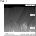
- FIG. 2 shows a dark field STEM image.
- the A layer on the substrate side and the B layer thereon are confirmed. It is confirmed that the B layer is finer than the A layer.
- FIG. 3 shows a cross-sectional TEM image of the A layer.
- FIG. 4 shows a cross-sectional TEM image of the B layer.
- the A layer consisted of columnar crystals
- the B layer consisted of columnar crystals and fine crystals.
- streaky phases having different brightnesses are confirmed.
- the crystal structure of the A layer consisted of cubic crystals.
- the crystal structure of the B layer consisted of cubic crystals and hexagonal crystals.
- regions that appeared bright in FIG. 1 had a relatively high Al content, and regions that appeared dark had a relatively low Al content.
- the region having a relatively high Al content had a larger amount of hexagonal AlN than that in the region having a relatively low Al content.
- Example 1 having the above-described microstructure had a small flank face maximum wear width and had more excellent durability than that of Comparative Example 1. It is presumed that Example 1 contained a large amount of Al, whereby damage to the tool is suppressed.
Landscapes
- Chemical & Material Sciences (AREA)
- Chemical Kinetics & Catalysis (AREA)
- Engineering & Computer Science (AREA)
- Materials Engineering (AREA)
- Mechanical Engineering (AREA)
- Metallurgy (AREA)
- Organic Chemistry (AREA)
- Inorganic Chemistry (AREA)
- Cutting Tools, Boring Holders, And Turrets (AREA)
- Physical Vapour Deposition (AREA)
Applications Claiming Priority (2)
| Application Number | Priority Date | Filing Date | Title |
|---|---|---|---|
| JP2022135974A JP2024032363A (ja) | 2022-08-29 | 2022-08-29 | 被覆工具 |
| PCT/JP2023/029736 WO2024048306A1 (fr) | 2022-08-29 | 2023-08-17 | Outil revêtu |
Publications (1)
| Publication Number | Publication Date |
|---|---|
| EP4582199A1 true EP4582199A1 (fr) | 2025-07-09 |
Family
ID=90099420
Family Applications (1)
| Application Number | Title | Priority Date | Filing Date |
|---|---|---|---|
| EP23860069.6A Pending EP4582199A1 (fr) | 2022-08-29 | 2023-08-17 | Outil revêtu |
Country Status (3)
| Country | Link |
|---|---|
| EP (1) | EP4582199A1 (fr) |
| JP (1) | JP2024032363A (fr) |
| WO (1) | WO2024048306A1 (fr) |
Family Cites Families (17)
| Publication number | Priority date | Publication date | Assignee | Title |
|---|---|---|---|---|
| JP5041222B2 (ja) * | 2007-07-24 | 2012-10-03 | 三菱マテリアル株式会社 | 表面被覆切削工具 |
| JP5099495B2 (ja) * | 2007-10-16 | 2012-12-19 | 三菱マテリアル株式会社 | 表面被覆切削工具 |
| JP5565630B2 (ja) * | 2010-11-12 | 2014-08-06 | 三菱マテリアル株式会社 | 耐摩耗性と仕上げ面精度に優れた表面被覆ブローチ |
| JP5035479B2 (ja) * | 2011-01-27 | 2012-09-26 | 三菱マテリアル株式会社 | 耐欠損性、耐摩耗性にすぐれた表面被覆切削工具 |
| JP5590331B2 (ja) * | 2011-02-14 | 2014-09-17 | 三菱マテリアル株式会社 | 耐摩耗性と切屑排出性に優れた表面被覆ドリル |
| WO2014034923A1 (fr) * | 2012-08-31 | 2014-03-06 | 株式会社タンガロイ | Outil de coupe enrobé |
| JP5975342B2 (ja) * | 2012-10-31 | 2016-08-23 | 三菱マテリアル株式会社 | 表面被覆切削工具 |
| JP6525310B2 (ja) | 2014-07-29 | 2019-06-05 | 日立金属株式会社 | 被覆工具 |
| JP6529262B2 (ja) * | 2015-01-07 | 2019-06-12 | 日立金属株式会社 | 被覆工具 |
| JP2016199793A (ja) * | 2015-04-13 | 2016-12-01 | 株式会社神戸製鋼所 | 硬質皮膜 |
| JP6789055B2 (ja) | 2016-10-04 | 2020-11-25 | 株式会社神戸製鋼所 | 硬質皮膜、硬質皮膜被覆部材及び硬質皮膜の製造方法 |
| WO2017179233A1 (fr) * | 2016-04-14 | 2017-10-19 | 住友電気工業株式会社 | Revêtement dur et outil de coupe |
| CN106191772B (zh) * | 2016-08-09 | 2018-07-31 | 上海理工大学 | 一种含有多相AlCrN纳米插入层的高硬度CrAlN涂层及其制备方法 |
| JP6958614B2 (ja) * | 2017-05-23 | 2021-11-02 | 住友電気工業株式会社 | 被膜および切削工具 |
| JP7054473B2 (ja) * | 2018-03-14 | 2022-04-14 | 三菱マテリアル株式会社 | 表面被覆切削工具 |
| JP6798534B2 (ja) * | 2018-09-11 | 2020-12-09 | 株式会社タンガロイ | 被覆切削工具 |
| JP2022135974A (ja) | 2021-03-04 | 2022-09-15 | 住友化学株式会社 | レジスト組成物及びレジストパターンの製造方法 |
-
2022
- 2022-08-29 JP JP2022135974A patent/JP2024032363A/ja active Pending
-
2023
- 2023-08-17 WO PCT/JP2023/029736 patent/WO2024048306A1/fr not_active Ceased
- 2023-08-17 EP EP23860069.6A patent/EP4582199A1/fr active Pending
Also Published As
| Publication number | Publication date |
|---|---|
| JP2024032363A (ja) | 2024-03-12 |
| WO2024048306A1 (fr) | 2024-03-07 |
Similar Documents
| Publication | Publication Date | Title |
|---|---|---|
| EP3715026B1 (fr) | Outil de coupe revêtu | |
| EP3437774B1 (fr) | Outil de coupe revêtu | |
| US10974323B2 (en) | Coated cutting tool | |
| EP4292735A1 (fr) | Outil revêtu | |
| JP7636492B2 (ja) | 被覆切削工具 | |
| IL209811A (en) | Hard coating and method of forming | |
| US11666976B2 (en) | Coated cutting tool | |
| EP4316707A1 (fr) | Outil de coupe revêtu | |
| JP6555796B2 (ja) | 被覆切削工具 | |
| JP5287124B2 (ja) | 硬質被覆層がすぐれた耐欠損性を発揮する表面被覆切削工具 | |
| US11965235B2 (en) | Coated cutting tool | |
| EP4582199A1 (fr) | Outil revêtu | |
| EP4389329A1 (fr) | Outil revêtu | |
| EP3670043B1 (fr) | Outil de coupe revêtu | |
| EP4582198A1 (fr) | Outil revêtu | |
| EP3943224A1 (fr) | Outil de coupe revêtu | |
| EP4545225A1 (fr) | Outil de coupe revêtu | |
| EP4732972A1 (fr) | Outil de coupe revêtu | |
| JP7760424B2 (ja) | 被覆部材 | |
| JP2024027836A (ja) | 被覆工具 |
Legal Events
| Date | Code | Title | Description |
|---|---|---|---|
| STAA | Information on the status of an ep patent application or granted ep patent |
Free format text: STATUS: THE INTERNATIONAL PUBLICATION HAS BEEN MADE |
|
| PUAI | Public reference made under article 153(3) epc to a published international application that has entered the european phase |
Free format text: ORIGINAL CODE: 0009012 |
|
| STAA | Information on the status of an ep patent application or granted ep patent |
Free format text: STATUS: REQUEST FOR EXAMINATION WAS MADE |
|
| 17P | Request for examination filed |
Effective date: 20250213 |
|
| AK | Designated contracting states |
Kind code of ref document: A1 Designated state(s): AL AT BE BG CH CY CZ DE DK EE ES FI FR GB GR HR HU IE IS IT LI LT LU LV MC ME MK MT NL NO PL PT RO RS SE SI SK SM TR |
|
| DAV | Request for validation of the european patent (deleted) | ||
| DAX | Request for extension of the european patent (deleted) |