EP4582308A2 - Indicateur de niveau à fibre optique - Google Patents
Indicateur de niveau à fibre optique Download PDFInfo
- Publication number
- EP4582308A2 EP4582308A2 EP24219350.6A EP24219350A EP4582308A2 EP 4582308 A2 EP4582308 A2 EP 4582308A2 EP 24219350 A EP24219350 A EP 24219350A EP 4582308 A2 EP4582308 A2 EP 4582308A2
- Authority
- EP
- European Patent Office
- Prior art keywords
- indicator
- indicator member
- housing
- child
- seat
- Prior art date
- Legal status (The legal status is an assumption and is not a legal conclusion. Google has not performed a legal analysis and makes no representation as to the accuracy of the status listed.)
- Pending
Links
Images




Classifications
-
- B—PERFORMING OPERATIONS; TRANSPORTING
- B60—VEHICLES IN GENERAL
- B60N—SEATS SPECIALLY ADAPTED FOR VEHICLES; VEHICLE PASSENGER ACCOMMODATION NOT OTHERWISE PROVIDED FOR
- B60N2/00—Seats specially adapted for vehicles; Arrangement or mounting of seats in vehicles
- B60N2/24—Seats specially adapted for vehicles; Arrangement or mounting of seats in vehicles for particular purposes or particular vehicles
- B60N2/26—Seats specially adapted for vehicles; Arrangement or mounting of seats in vehicles for particular purposes or particular vehicles for children
- B60N2/266—Seats specially adapted for vehicles; Arrangement or mounting of seats in vehicles for particular purposes or particular vehicles for children with detection or alerting means responsive to presence or absence of children; with detection or alerting means responsive to improper locking or installation of the child seats or parts thereof
- B60N2/268—Seats specially adapted for vehicles; Arrangement or mounting of seats in vehicles for particular purposes or particular vehicles for children with detection or alerting means responsive to presence or absence of children; with detection or alerting means responsive to improper locking or installation of the child seats or parts thereof detecting or alerting means responsive to the installation of the child seats in the vehicle
-
- B—PERFORMING OPERATIONS; TRANSPORTING
- B60—VEHICLES IN GENERAL
- B60N—SEATS SPECIALLY ADAPTED FOR VEHICLES; VEHICLE PASSENGER ACCOMMODATION NOT OTHERWISE PROVIDED FOR
- B60N2/00—Seats specially adapted for vehicles; Arrangement or mounting of seats in vehicles
- B60N2/24—Seats specially adapted for vehicles; Arrangement or mounting of seats in vehicles for particular purposes or particular vehicles
- B60N2/26—Seats specially adapted for vehicles; Arrangement or mounting of seats in vehicles for particular purposes or particular vehicles for children
- B60N2/28—Seats readily mountable on, and dismountable from, existing seats or other parts of the vehicle
- B60N2/2821—Seats readily mountable on, and dismountable from, existing seats or other parts of the vehicle having a seat and a base part
-
- B—PERFORMING OPERATIONS; TRANSPORTING
- B62—LAND VEHICLES FOR TRAVELLING OTHERWISE THAN ON RAILS
- B62B—HAND-PROPELLED VEHICLES, e.g. HAND CARTS OR PERAMBULATORS; SLEDGES
- B62B9/00—Accessories or details specially adapted for children's carriages or perambulators
- B62B9/005—Safety means for traffic, e.g. lights, reflectors, mirrors etc.
-
- G—PHYSICS
- G01—MEASURING; TESTING
- G01C—MEASURING DISTANCES, LEVELS OR BEARINGS; SURVEYING; NAVIGATION; GYROSCOPIC INSTRUMENTS; PHOTOGRAMMETRY OR VIDEOGRAMMETRY
- G01C9/00—Measuring inclination, e.g. by clinometers, by levels
- G01C9/12—Measuring inclination, e.g. by clinometers, by levels by using a single pendulum
Definitions
- Exemplary embodiments of the disclosure relate to a level indicator, and in some embodiments to a level indicator for use with a child safety system.
- a child safety system is used to transport children and is typically designed for use in an automobile vehicle to properly restrain a child in the event of accident.
- a child safety system is design to meet the Federal Motor Vehicle Safety Standards when properly installed within a vehicle. However, most child safety seats are incorrectly installed. To improve installation within a vehicle, some child safety seats include a means to level the child safety seat relative to the vehicle seat angle. While existing indicators, such as bubbles levels, provide angle feedback of the child safety seat, these indicators can be difficult to see and can be read incorrectly due to refraction of light.
- a level indicator including a housing and an indicator member rotatable relative to the housing.
- the indicator member is biased by gravity to a resting position.
- the indicator member has a luminescent visual indicator.
- the luminescent visual indicator indicates a position of the indicator member relative to the housing.
- the indicator member includes a light transmission member and a portion of the light transmission member forms the luminescent visual indicator.
- the light transmission member is a fiber optic filament.
- the fiber optic filament is colored.
- the luminescent visual indicator is arranged at an end of the indicator member.
- an end of the fiber optic filament is arranged adjacent to the end of the indicator member.
- the fiber optic filament is arranged within an interior of a body of the indicator member.
- the first end is disposed vertically beneath the second end.
- the first end of the indicator member is weighted.
- the visual indicator of the indicator member is arranged at a second, opposite end of the visual indicator.
- the indicator member includes a weight.
- the visual indicator of the indicator member and the weight of the indicator member are arranged at opposite sides of an axis of rotation of the indicator member.
- the indicator member is rotatable relative to the housing about the axis of rotation.
- At least a portion of the indicator member is arranged within an interior of the housing.
- a cover connectable to the housing.
- the indicator member is arranged within a cavity defined between the housing and the cover.
- a child seat component includes a seat body and a level indicator operably coupled to the body.
- the level indicator has a luminescent visual indicator operable to indicate a position of the seat body relative to a horizontal plane.
- the seat body is a support base of a child safety system.
- the seat body is a child seat of a child safety system.
- the level indicator further includes a housing and an indicator member rotatable relative to the housing and biased by gravity to a resting position.
- the luminescent visual indicator is arranged at the indicator member.
- the indicator member includes a light transmission member and a portion of the light transmission member forms the luminescent visual indicator.
- the light transmission member is a fiber optic filament.
- the fiber optic filament is colored.
- the luminescent visual indicator is arranged at an end of the indicator member.
- an end of the light transmission member is arranged adjacent to the end of the indicator member.
- the indicator member includes an indicator member body and the fiber optic filament is arranged within an interior of the indicator member body.
- the indicator member has a first end and a second end and a center of mass of the indicator member is located closer to the first end than the second end.
- the first end is disposed vertically beneath the second end.
- the first end of the indicator member is enlarged relative to a remainder of the indicator member.
- the first end of the indicator member is weighted.
- the visual indicator is arranged at a second, opposite end of the visual indicator.
- the indicator member includes a weight.
- the visual indicator and the weight are arranged at opposite sides of an axis of rotation of the indicator member.
- the indicator member is rotatable about the axis of rotation relative to the housing.
- a child furniture item includes a body operable to support a child and a level indicator associated with the body to identify a level position of the body.
- the level indicator includes a housing and an indicator member rotatable relative to the housing. The indicator member is biased by gravity to a resting position. The indicator member has a luminescent visual indicator. The luminescent visual indicator indicates a position of the indicator member relative to the housing
- the child furniture item is a high chair.
- the child furniture item is child seat.
- the child furniture item is a playard or pack and play.
- the child furniture item is a stroller.
- the indicator member includes a light transmission member, and a portion of the light transmission member forms the luminescent visual indicator.
- the light transmission member is a fiber optic filament.
- the light transmission member is arranged within an interior of a body of the indicator member.
- the luminescent visual indicator is arranged at an end of the indicator member.
- the indicator member has a first end and a second end, and a center of mass of the indicator member is located closer to the first end than the second end.
- the first end of the indicator member is enlarged relative to a remainder of the indicator member.
- the first end of the indicator member is weighted.
- the level indicator 20 includes a housing 22 and an indicator member 24 movable relative to the housing 22.
- Suitable materials for the housing 22 include but are not limited to rigid plastic or composite materials for example.
- a pin or shaft 26 protrudes from a surface of the housing 22, such as an interior surface of the housing 22 for example.
- the pin 26 may be integrally formed with the housing 22, or alternatively, may be a separate component mounted to the housing 22.
- the indicator member 24 is configured to at least partially rotate about the longitudinal axis X of the pin 26. In an embodiment, the indicator member 24 is rotatably mounted to the pin 26.
- the indicator member 24 may include an elongated rigid body 30 having a first end 32 and an opposite, second end 34.
- the first end 32 of the body 30 is configured to facilitate rotation of the indicator member 24 to a resting or equilibrium position.
- the first end 32 of the body 30 is enlarged relative to the remainder of the body 30.
- a width of the body 30 at the first end 32 may be greater than the width of the body 30 at the second end 34 and/or at a generally central portion the body 30.
- the first end 32 of the body 30 may be weighted or include a mass that intentionally adds weight to the first end 32.
- the center of mass of the indicator member 24 is positioned closer to the first end 32 than the second end 34. Because the indicator member 24 is rotatably mounted about the pin 26, the indicator member 24 is operable in a manner similar to a pendulum with the first end 32 of the indicator member 24 acting as a pendulum bob. The gravitational forces acting on the first end 32 of the indicator member will cause the indicator member 24 to rotate freely about the pin 26 and its axis X until the indicator member reaches a resting, equilibrium position. In the resting, equilibrium position, the indicator member 24 may be oriented generally vertically with the first end 32 of the body 30 being aligned with and arranged beneath the second end 34.
- a portion of the indicator member 24, such as the second end 34 thereof for example, may be operable to indicate to a user a position of indicator member 24 relative to the housing 22. Accordingly, the visual indicator and the weight are arranged at opposite sides of the axis of rotation of the indicator member.
- the second end 34 of the indicator member 24 may be a luminescent visual indicator. In an embodiment, a visible light is emitted at the second end 34 of the indicator member 24, and this light is the visual indicator.
- the body 30 of the indicator member 24 may include one or more light transmission members 40 that form the visual indicator by emitting visible light at the second end 34 of the body 30.
- the light transmission member 40 in the non-limiting embodiments described herein is a fiber optic element, it should be understood that the use of any suitable light transmission member, such as a light pipe for example, is within the scope of the disclosure.
- the light is emitted from an end 42 of the fiber optic filament 40.
- the end 42 of the at least one fiber optic filament 40 is arranged at or near the second end 34 of the body 30 such that the light emitted therefrom is visible at the second end 34 of the indicator member.
- the fiber optic filament 40 is configured to gather the surrounding ambient light and output it at an end thereof. Further, the light output from the fiber optic filament 40 may be concentrated, making it easier to see. In some embodiments, the fiber optic filament 40 may have a color embedded therein. As a result, the concentrated light emitted from the second end 34 of the indicator member 24 may be the same color as the fiber optic filament 40 through which the light was transmitted.
- the one or more fiber optic filaments 40 may be mounted to or may be positioned within the body 30 of the indicator member 24.
- the at least one fiber optic filament 40 is arranged at least partially within an interior of the body 30 of the indicator member 24, light must be able to pass through the body 30 to the at least one fiber optic filament 40.
- the body 30 of the indicator member 24 may have one or more openings formed therein.
- all or at least a portion of the body 30 may be translucent such that ambient or surrounding light can transmit through the body 30 into the fiber optic filament 40.
- another light source is associated with the at least one fiber optic filament 40 and is configured to transmit light therethrough are also within the scope of the disclosure.
- a luminescent material may be positioned adjacent to the first end 32 of the indicator member 24, such as on the inner part of the housing for example, and may be the source of the light transmitted through the light transmission member 40.
- light from a powered light source (not shown), such as a light emitting diode (LED) for example, may be transmitted to the light transmission member 40 to form a visual indicator at the indicator member 24.
- the body 30 of the indicator member 24 need not include windows or be translucent and the fiber optic filament 40 may include a cladding or jacket.
- a powered light source may be arranged at an interior of the housing 22, or alternatively, may be located near the housing 22, such as on an adjacent portion of a child seat for example, as will be described in more detail below. In other embodiments, the light source may be arranged at or near any surface that allows the light emitted therefrom to transmit toward the light transmission member 40.
- the housing 22 may have a first end 50 and one or more sidewalls 52 connected to and extending from the first end 50 to define a hollow interior 54 ( FIG. 3 ) within which at least a portion of the indicator member 24 is received.
- the first end 50 of the housing 22 is closed.
- the first end 52 of the housing 22 may have a curved or arcuate contour complementary to the path of movement of the first end 32 of the indicator member 24.
- a cover 56 is arranged at or is connectable to the housing 22.
- the cover 56 may be connectable to the second, opposite end 58 of one or more of the sidewalls 52, in an area proximate the second end 34 of the body 30 of the indicator member 24.
- the cover 56 may similarly have a hollow interior 60. Accordingly, when mounted about the housing 22, the interior 60 of the cover 56 may cooperate with the interior 54 of the housing 22 to receive the indicator member 24, in its entirety, between the housing 22 and the cover 56.
- the cover 56 may have a curved or arcuate contour generally complementary to path of movement of the second end 34 of the indicator member 24 as the indicator member rotates about the axis X.
- the cover 56 may be translucent, or at least partially translucent, such that the light emitted from the indicator member 24 is visible therethrough.
- the translucence of the cover 56 is generally constant over the path of movement of the second end 34 of the indicator member 24.
- the cover 56 may have regions with varying degrees of translucence.
- a first region 62 of the cover 56 such as a central region aligned with the axis X, may have a greater translucence than a second region 64 of the cover 56, such as arranged at a lateral side of the first region 62.
- the housing 22 and/or cover 56 of the level indicator 20 includes one or more mounting features 70 for positioning or mounting the level indicator 20 to a component, as will be described in more detail below. Accordingly, the level indicator 20 is operable to monitor an orientation of the component to which the level indicator 20 is connected via the one or more mounting features 70. In an embodiment, the level indicator 20 is operable to monitor a position of the component relative to a horizontal plane. The gravity acting on the indicator member 24 will cause the indicator member 24 to come to a rest in a vertical position, with the second end 34 arranged vertically above the first end 32. By connecting the housing 22 to the component, the housing 22 is configured to move with the component relative to the horizontal plane.
- the light emitted by the indicator member 24 will be visible at a first region 62 of the cover 56, such as near a center of the cover 56 for example.
- the housing 22 will also be arranged the same non-parallel angle relative to horizontal.
- the light emitted by the indicator member 24 will be visible at a second region 64 of the cover 56, such as near a side of the cover 56 for example.
- the positioning of the second end 34, and therefore the visible light emitted by the indicator member 24, at a position offset from the middle of center of the cover 56 may indicate to a user a direction and relative angle of the housing 22, and therefore of the component, to a horizontal plane.
- the cover 56 may include one or more markings 80a, 80b, 82a, 82b indicating a suitable range of positioning of the indicator member 32.
- the markings 80a, 80b, 82a, 82b may be formed at the second region 64 of the cover 56.
- the cover 56 includes at least one first marking 80a 80b and at least one second marking 82a, 82b.
- the at least one first markings 80a, and 80b may indicate to a user a suitable position (or range of positions) of the second end 34 of the indicator member 24 relative to the cover 56 associated with operation of the level indicator 20 in a first configuration.
- the at least one second markings 82a, 82b may indicate to a user a suitable position (or range of positions) of the second end 34 of the indicator member 24 relative to the cover 56 associated with operation of the level indicator 20 in a second configuration.
- the level indicator 20 may be used with a child safety system, and the first and second configurations of the level indicator 20 may be determined by a corresponding configuration of the child safety system.
- the level indicator 20 may be operable in the first configuration when the child safety system is in a rearward-facing orientation. In this first configuration, the child safety system may be in a level condition when the visual indicator of the indicator member 32 is positioned between the markings 80a and 80b, particularly at an area at or proximate a center point between the two markings 80a, 80b.
- the level indicator 20 may be operable in the second configuration when the child safety system is in a forward-facing orientation.
- the child safety system When in the second configuration, the child safety system may be in a level condition when the visual indicator of the indicator member 32 is positioned between the markings 82a and 82b, such as at an area at or proximate a center point between the two markings 82a, 82b.
- first and second markings 80a, 80b, 82a, 82b are illustrated and described with respect to use of the level indicator 20 in first and second configurations, it should be understood that in some embodiments, one or more markings may be used to identify a suitable position of the second end 34 of the indicator member 24 relative to the cover 56 associated with operation of the level indicator 20 in both the first configuration and the second configuration.
- a level indicator 20 as illustrated and described herein may be adapted for use in any suitable application.
- the level indicator 20 may be used to monitor the position of a child safety system.
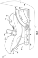
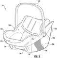
- the child safety system 100 includes a support base 102 and a child seat 104 connectable to the support base 102. As shown, the child seat 104 is removably connectable to the support base 102. However, in other embodiments, the child seat 104 may be permanently connected to the support base 102.
- the support base 102 may be positionable in direct contact with a support surface, such as of a vehicle seat 106 for example, and may be attached to the vehicle seat 106 via a connector of a "lower anchor and tether for children" e.g., LATCH system.
- the support base 102 may be detachably coupled to a vehicle seat 106 via a vehicle belt (not shown) associated with the vehicle seat 106.
- the support base 102 includes a rigid body 110 adapted to support the child seat 104 thereon. Suitable materials for making the support base 102 include but are not limited to rigid plastic or composite materials for example.
- the rigid body 110 typically includes a base seat portion 112 and a base backrest portion 114 extending at an angle relative to the base seat portion 112.
- the base seat portion 112 and the base backrest portion 114 are illustrated as being integrally formed as a unitary body, embodiments where the base seat portion 112 and the base backrest portion 114 are separate components removably or permanently connected together are also within the scope of the disclosure. It should be understood that the support base 102 illustrated and described herein is intended as an example only and that a support base having another configuration is also contemplated herein.
- the child seat 104 connectable to the support base 102 is an infant child seat.
- infant child seat refers to such a seat as would be defined by one of ordinary skill in the art.
- an infant child seat may be described as a seat for use by an infant or child too small to use a convertible child seat and may include a carrying handle to allow for portability of the infant child seat external to the vehicle.
- an infant car seat When mounted about a support base 102, an infant car seat may not be configured to move, for example rotate or incline relative to the support base 102.
- the child seat 104 can include a seat body formed from a seat shell 120 and in some embodiments a seat rim 122.
- the seat shell 120 alone or in combination with the seat rim 122 may define a seat pan or seat portion 124 and a seat back or upright portion 126 of the child seat 104.
- the seat back 126 is typically arranged at an angle relative to the seat pan 124.
- the seat pan 124 and the seat back 126 may be detachably coupled, or alternatively, may be permanently coupled.
- the seat shell 120 may be a single, substantially solid, or partially hollow structure defining the seat pan 124 and the seat back 126.
- One or more seat pads, cushions, soft goods, or the like may be disposed in overlapping arrangement with one or more surfaces of the seat pan 124 and/or with one or more surfaces of the seat back 126 to comfortably support a child that is positioned within the child seat 104.
- the bottom of the seat shell 120 may include a first seat shell rail 128 and a second seat shell rail 130 arranged at opposing sides of the child seat 104.
- the first and second seat shell rails 128, 130 may have respective curved rocker bottoms to enable a rocking motion to comfort a child positioned within the child seat 104 when the child seat is supported on a generally flat or planar surface (e.g., in a home environment, restaurant, etc.).
- the child seat 104 may include a carrying handle 132.
- the carrying handle 132 has a generally arcuate shape and the two opposite ends 134, 136 thereof are respectively connected with a left and right side of the seat shell 120 via respective attachment mechanisms (not shown).
- the carrying handle 132 is movably connected with the seat shell 120 and/or the seat rim 122. Accordingly, the carrying handle 132 may be transformable, for example rotatable, between a plurality of positions or angles relative to the seat shell 120, such as to more easily access the child positioned within the child seat 104 or for storage purposes for example.
- the attachment mechanisms used to affix the handle to the seat shell 120 may include integrated locking mechanisms (not shown) to maintain the carrying handle 132 at a desired orientation with respect to the seat shell 120.
- the child seat 104 may be connectable to the support base 102 to mount the child seat 104 relative to the vehicle seat 106. However, in some embodiments, the child seat 104 may be positionable in direct contact with the vehicle seat 106. For example, the child seat 104 may be detachably fixed to a vehicle seat 106, such as via a latch or anchor mechanism (not shown), or via a vehicle belt (not shown) associated with the vehicle seat 10.
- At least one level indicator is arranged at the support base 102 of the child safety system 100 to monitor an orientation of the support base 102 relative to a horizontal plane or to the vehicle seat 106.
- the level indicator 20 may be located at any position of the body 110 where it is visible to a user.
- the level indicator 20 is positioned such that the cover 56 and/or the end 34 of the level indicator 24 is visible at an upper surface of the support base 102 and may but need not be arranged near an edge of the support base 102.
- the level indicator 20 may but need not be visible when the child seat 104 is attached to the support base 102.
- the one or more mounting features 70 of the housing 22 of the level indicator 20 may be connectable to the body 110, such as at the base seat portion 112, the base backrest portion 114 or both.
- the level indicator 20 may be integrally formed with the body 110 of the support base 102.
- the housing 22 of the level indicator 20 may be formed at least partially by a portion of the body 110 of the support base 102.
- the housing 22 of the level indicator 20 is configured to move, with the support base 102. Accordingly, during installation of the support base 102, as the angle of the support base 102 is adjusted, the angle of the housing 22 will similarly vary. During this movement, the level indicator 20 will indicate to the user a relative position of the housing 22, and therefore the support base 102, relative to a horizontal plane.
- a level indicator 20 may be mounted to the child seat 104 of the child safety system 100 to monitor an orientation of the child seat 104 relative to one or more of the support base 102, the vehicle seat 106, and a horizontal plane.
- the level indicator 20 may be located at any position of the child seat 104 visible to a user.
- the level indicator 20 may be positioned such that the cover 56 and/or the end 34 of the level indicator 24 is visible at the seat rim 122 or at an exterior or side surface of the seat shell 120.
- the level indicator 20 may be positioned at one or both of the seat pan 124 and the seat back 126 for example.
- the one or more mounting features 70 of the housing 22 or cover 56 may be connectable to a surface of the seat shell 120, such as at a side of the seat pan 124, the seat back 126, or both.
- the level indicator 20 may be integrally formed with a portion of the seat shell 120.
- the housing 22 of the level indicator 20 is configured to move with the child seat 104, relative to the support base 102 and the vehicle seat 106. Accordingly, during installation of the child seat 104, as an angle of the child seat 104 is adjusted, the angle of the housing 22 will similarly vary. During this movement, the level indicator 20 will indicate to the user a relative position of the housing 22, and therefore of the child seat 104.
- FIGS. 6-9 Another example of a child safety system 200 is illustrated in FIGS. 6-9 . Similar to the previous embodiment, the child safety system 200 includes a support base 202 and a rigid child seat 204 connected to the support base 202.
- the support base 202 may be detachably fixed to a vehicle seat 206, such as via a LATCH system, not shown in the FIGS.
- the support base 202 may be detachably affixed to a vehicle seat 206 via a vehicle belt associated with the vehicle seat 206 or any other suitable means.
- the rigid child seat 204 is connected to the support base 202.
- the child seat 204 is permanently connected or affixed to the support base 202.
- the term "permanently connected” represents embodiments where the child seat 204 is not intended to be disassembled from the support base 202 by a user.
- the support base 202 may be integrally formed with the child seat.
- the child seat 204 may be detachably coupled to the support base 202, thereby allowing the child seat 204 to be separated from the support base 202.
- the child seat 204 includes a seat shell 210 having a seat portion 212 and a backrest or upright portion 214 arranged at an angle relative to the seat portion 212.
- the seat portion 212 and the upright portion 214 may be detachably coupled, or alternatively, may be permanently coupled.
- the upright portion 214 and the seat portion 212 are integrally formed as a single unitary body.
- the upright portion 214 can be rotationally connected to the seat portion 212 such that the upright portion 214 can incline and recline relative to the seat portion 212.
- the upright portion 214 of the seat shell 210 includes an upright support surface 220 generally facing forward and that extends from a first end or top 222 to a second, opposite end or bottom 224 of the upright portion 214.
- a first upright side member 226 may be arranged at a first side 228 of the upright support surface 220 and a second upright side member 230 may be arranged at a second, opposite side 232 of the upright support surface 220.
- the first and second upright side members 226, 230 therefore form the left side and the right side of the upright portion 214, respectively.
- the first and second upright side members 226, 230 extend forward from the upright support surface 220.
- the first and second upright side members 226, 230 may extend generally orthogonally to the upright support surface 220, or alternatively, may extend therefrom at another angle, such as an angle greater than 90° for example. Accordingly, the upright support surface 220 and the first and second upright side members 226, 230 define a backrest region or upright support cavity or region within which an upper body of a child is received.
- the upright portion 214 of the seat shell 210 includes a headrest 234.
- the headrest 234 is attached to or integral with the upright portion 28.
- the headrest 234 may be stationary or in some embodiments, may be configured to move relative to the upright support surface 220.
- the headrest 234 may be configured to translate relative to the upright support surface 220 between a retracted position and an extended position, allowing for adjustment based on the size of the child positioned within the child safety system 200.
- the seat side members 246, 250 extend at an angle from the seat support surface 240.
- the angle of the first seat side member 246 relative to the seat support surface 240 may but need not be the same as the angle of the first upright side member 226 relative to the upright support surface 220.
- the angle of the second seat side member 250 relative to the seat support surface 240 may but need not be the same as the angle of the second upright side member 230 relative to the upright support surface 220.
- the first upright side member 226 and the first seat side member 246 are integrally formed and the second upright side member 230 and the second seat side member 250 are integrally formed.
- At least one level indicator is arranged at the support base 202 of the child safety system 200 to monitor an orientation of a portion of the support base 202.
- a level indicator 20 is operable to monitor a position of a bottom surface of the support base 202 relative to a horizontal plane or to the vehicle seat 206.
- a level indicator 20 arranged at the support base 202 may be operable to indicate a position of the child seat 204 relative to a horizontal plane or to the vehicle seat 206.
- a portion of the support base 202 (not shown), also referred to herein as a "recline portion”, may be movable within the child seat 204 to control the incline and recline of the child seat 204.
- a level indicator 20 may be operably coupled to the recline portion of the support base 202 such that the level indicator 20 indicates the recline of the child seat 204.
- a level indicator 20 may be mounted to directly the child seat 204 of the child safety system 200 to indicate an orientation of the child seat 104, such as the recline of the child seat 204 for example, relative to one or more of the support base 202, the vehicle seat 206, and a horizontal plane.
Landscapes
- Engineering & Computer Science (AREA)
- Health & Medical Sciences (AREA)
- Transportation (AREA)
- Mechanical Engineering (AREA)
- Child & Adolescent Psychology (AREA)
- Aviation & Aerospace Engineering (AREA)
- General Health & Medical Sciences (AREA)
- Combustion & Propulsion (AREA)
- General Physics & Mathematics (AREA)
- Radar, Positioning & Navigation (AREA)
- Remote Sensing (AREA)
- Physics & Mathematics (AREA)
- Chemical & Material Sciences (AREA)
- Public Health (AREA)
- Seats For Vehicles (AREA)
- Level Indicators Using A Float (AREA)
Applications Claiming Priority (2)
| Application Number | Priority Date | Filing Date | Title |
|---|---|---|---|
| US202363609162P | 2023-12-12 | 2023-12-12 | |
| US18/968,112 US20250187511A1 (en) | 2023-12-12 | 2024-12-04 | Fiber optic level indicator |
Publications (2)
| Publication Number | Publication Date |
|---|---|
| EP4582308A2 true EP4582308A2 (fr) | 2025-07-09 |
| EP4582308A3 EP4582308A3 (fr) | 2025-09-03 |
Family
ID=94116899
Family Applications (1)
| Application Number | Title | Priority Date | Filing Date |
|---|---|---|---|
| EP24219350.6A Pending EP4582308A3 (fr) | 2023-12-12 | 2024-12-12 | Indicateur de niveau à fibre optique |
Country Status (1)
| Country | Link |
|---|---|
| EP (1) | EP4582308A3 (fr) |
Family Cites Families (5)
| Publication number | Priority date | Publication date | Assignee | Title |
|---|---|---|---|---|
| US2877561A (en) * | 1955-05-16 | 1959-03-17 | William L Morse | Angular position indicator |
| JPH11291799A (ja) * | 1998-04-09 | 1999-10-26 | Combi Corp | チャイルドシート |
| CN203637612U (zh) * | 2013-11-19 | 2014-06-11 | 宁波妈咪宝婴童用品制造有限公司 | 儿童安全座椅底座水平显示装置 |
| US10737593B1 (en) * | 2018-07-02 | 2020-08-11 | Summer Infant (Usa), Inc. | Car seat |
| CN116164702B (zh) * | 2023-04-21 | 2023-07-21 | 青岛瑞源工程集团有限公司 | 一种用于建筑施工工程测量的水准仪 |
-
2024
- 2024-12-12 EP EP24219350.6A patent/EP4582308A3/fr active Pending
Also Published As
| Publication number | Publication date |
|---|---|
| EP4582308A3 (fr) | 2025-09-03 |
Similar Documents
| Publication | Publication Date | Title |
|---|---|---|
| US7472955B2 (en) | Infant car seat | |
| US5551751A (en) | Reclining restraint (smart move) | |
| US7278683B2 (en) | Child seat with object holder | |
| US6739661B1 (en) | Pivotable reclining child safety car seat | |
| CN1321831C (zh) | 一种婴儿车 | |
| US6857700B2 (en) | Adjustable child seat for toddlers to small children | |
| US20160221480A1 (en) | Multi-position rear-facing child seat | |
| CN104590069B (zh) | 用于汽车座椅的脚踏板 | |
| US9629476B1 (en) | Convertible child seat | |
| CN101299949A (zh) | 儿童运动装置 | |
| CN204547845U (zh) | 汽车儿童安全座椅 | |
| AU2006292651A1 (en) | Adjustable head rest for child car seat | |
| GB2247614A (en) | Infant seat apparatus | |
| KR101328828B1 (ko) | 어린이 안전시트용 머리받침, 및 어린이용 안전시트 | |
| KR20120007961A (ko) | 육아 기구의 좌석 구조 | |
| ES2887748T3 (es) | Silla de seguridad para niños para un coche | |
| EP4582308A2 (fr) | Indicateur de niveau à fibre optique | |
| US20250187511A1 (en) | Fiber optic level indicator | |
| US8057272B1 (en) | Infant flotation device | |
| CN209063935U (zh) | 一种儿童约束系统 | |
| EP0832811A1 (fr) | Siège de bébé pour bicyclette | |
| RU2006146873A (ru) | Детское безопасное сиденье | |
| GB2414660A (en) | Child seat with adjustable length seat squab | |
| EP1167115B1 (fr) | Siège pour enfant | |
| CN221914138U (zh) | 儿童座椅和座椅接收部件 |
Legal Events
| Date | Code | Title | Description |
|---|---|---|---|
| PUAI | Public reference made under article 153(3) epc to a published international application that has entered the european phase |
Free format text: ORIGINAL CODE: 0009012 |
|
| STAA | Information on the status of an ep patent application or granted ep patent |
Free format text: STATUS: THE APPLICATION HAS BEEN PUBLISHED |
|
| AK | Designated contracting states |
Kind code of ref document: A2 Designated state(s): AL AT BE BG CH CY CZ DE DK EE ES FI FR GB GR HR HU IE IS IT LI LT LU LV MC ME MK MT NL NO PL PT RO RS SE SI SK SM TR |
|
| PUAL | Search report despatched |
Free format text: ORIGINAL CODE: 0009013 |
|
| AK | Designated contracting states |
Kind code of ref document: A3 Designated state(s): AL AT BE BG CH CY CZ DE DK EE ES FI FR GB GR HR HU IE IS IT LI LT LU LV MC ME MK MT NL NO PL PT RO RS SE SI SK SM TR |
|
| RIC1 | Information provided on ipc code assigned before grant |
Ipc: B60N 2/26 20060101AFI20250729BHEP Ipc: B60N 2/28 20060101ALI20250729BHEP Ipc: G01C 9/12 20060101ALI20250729BHEP Ipc: A47D 1/00 20060101ALI20250729BHEP Ipc: A47D 13/00 20060101ALI20250729BHEP Ipc: B62B 7/00 20060101ALI20250729BHEP |
|
| STAA | Information on the status of an ep patent application or granted ep patent |
Free format text: STATUS: REQUEST FOR EXAMINATION WAS MADE |
|
| 17P | Request for examination filed |
Effective date: 20260302 |