EP4582511A1 - Kautschuk-russ herstellung in einem pyrolyse und vergasung mehretagenofen - Google Patents
Kautschuk-russ herstellung in einem pyrolyse und vergasung mehretagenofen Download PDFInfo
- Publication number
- EP4582511A1 EP4582511A1 EP24150497.6A EP24150497A EP4582511A1 EP 4582511 A1 EP4582511 A1 EP 4582511A1 EP 24150497 A EP24150497 A EP 24150497A EP 4582511 A1 EP4582511 A1 EP 4582511A1
- Authority
- EP
- European Patent Office
- Prior art keywords
- pyrolysis
- hearth
- zone
- reactor
- gasification
- Prior art date
- Legal status (The legal status is an assumption and is not a legal conclusion. Google has not performed a legal analysis and makes no representation as to the accuracy of the status listed.)
- Pending
Links
Images

Classifications
-
- C—CHEMISTRY; METALLURGY
- C09—DYES; PAINTS; POLISHES; NATURAL RESINS; ADHESIVES; COMPOSITIONS NOT OTHERWISE PROVIDED FOR; APPLICATIONS OF MATERIALS NOT OTHERWISE PROVIDED FOR
- C09C—TREATMENT OF INORGANIC MATERIALS, OTHER THAN FIBROUS FILLERS, TO ENHANCE THEIR PIGMENTING OR FILLING PROPERTIES ; PREPARATION OF CARBON BLACK ; PREPARATION OF INORGANIC MATERIALS WHICH ARE NO SINGLE CHEMICAL COMPOUNDS AND WHICH ARE MAINLY USED AS PIGMENTS OR FILLERS
- C09C1/00—Treatment of specific inorganic materials other than fibrous fillers; Preparation of carbon black
- C09C1/44—Carbon
- C09C1/48—Carbon black
- C09C1/482—Preparation from used rubber products, e.g. tyres
-
- C—CHEMISTRY; METALLURGY
- C10—PETROLEUM, GAS OR COKE INDUSTRIES; TECHNICAL GASES CONTAINING CARBON MONOXIDE; FUELS; LUBRICANTS; PEAT
- C10B—DESTRUCTIVE DISTILLATION OF CARBONACEOUS MATERIALS FOR PRODUCTION OF GAS, COKE, TAR, OR SIMILAR MATERIALS
- C10B19/00—Heating of coke ovens by electrical means
-
- C—CHEMISTRY; METALLURGY
- C10—PETROLEUM, GAS OR COKE INDUSTRIES; TECHNICAL GASES CONTAINING CARBON MONOXIDE; FUELS; LUBRICANTS; PEAT
- C10B—DESTRUCTIVE DISTILLATION OF CARBONACEOUS MATERIALS FOR PRODUCTION OF GAS, COKE, TAR, OR SIMILAR MATERIALS
- C10B49/00—Destructive distillation of solid carbonaceous materials by direct heating with heat-carrying agents including the partial combustion of the solid material to be treated
- C10B49/02—Destructive distillation of solid carbonaceous materials by direct heating with heat-carrying agents including the partial combustion of the solid material to be treated with hot gases or vapours, e.g. hot gases obtained by partial combustion of the charge
-
- C—CHEMISTRY; METALLURGY
- C10—PETROLEUM, GAS OR COKE INDUSTRIES; TECHNICAL GASES CONTAINING CARBON MONOXIDE; FUELS; LUBRICANTS; PEAT
- C10B—DESTRUCTIVE DISTILLATION OF CARBONACEOUS MATERIALS FOR PRODUCTION OF GAS, COKE, TAR, OR SIMILAR MATERIALS
- C10B53/00—Destructive distillation, specially adapted for particular solid raw materials or solid raw materials in special form
- C10B53/07—Destructive distillation, specially adapted for particular solid raw materials or solid raw materials in special form of solid raw materials consisting of synthetic polymeric materials, e.g. tyres
-
- C—CHEMISTRY; METALLURGY
- C10—PETROLEUM, GAS OR COKE INDUSTRIES; TECHNICAL GASES CONTAINING CARBON MONOXIDE; FUELS; LUBRICANTS; PEAT
- C10B—DESTRUCTIVE DISTILLATION OF CARBONACEOUS MATERIALS FOR PRODUCTION OF GAS, COKE, TAR, OR SIMILAR MATERIALS
- C10B7/00—Coke ovens with mechanical conveying means for the raw material inside the oven
- C10B7/02—Coke ovens with mechanical conveying means for the raw material inside the oven with rotary scraping devices
-
- C—CHEMISTRY; METALLURGY
- C10—PETROLEUM, GAS OR COKE INDUSTRIES; TECHNICAL GASES CONTAINING CARBON MONOXIDE; FUELS; LUBRICANTS; PEAT
- C10J—PRODUCTION OF PRODUCER GAS, WATER-GAS, SYNTHESIS GAS FROM SOLID CARBONACEOUS MATERIAL, OR MIXTURES CONTAINING THESE GASES; CARBURETTING AIR OR OTHER GASES
- C10J3/00—Production of combustible gases containing carbon monoxide from solid carbonaceous fuels
- C10J3/58—Production of combustible gases containing carbon monoxide from solid carbonaceous fuels combined with pre-distillation of the fuel
- C10J3/60—Processes
- C10J3/62—Processes with separate withdrawal of the distillation products
-
- F—MECHANICAL ENGINEERING; LIGHTING; HEATING; WEAPONS; BLASTING
- F27—FURNACES; KILNS; OVENS; RETORTS
- F27B—FURNACES, KILNS, OVENS OR RETORTS IN GENERAL; OPEN SINTERING OR LIKE APPARATUS
- F27B9/00—Furnaces through which the charge is moved mechanically, e.g. of tunnel type; Similar furnaces in which the charge moves by gravity
- F27B9/06—Furnaces through which the charge is moved mechanically, e.g. of tunnel type; Similar furnaces in which the charge moves by gravity heated without contact between combustion gases and charge; electrically heated
- F27B9/062—Furnaces through which the charge is moved mechanically, e.g. of tunnel type; Similar furnaces in which the charge moves by gravity heated without contact between combustion gases and charge; electrically heated electrically heated
-
- F—MECHANICAL ENGINEERING; LIGHTING; HEATING; WEAPONS; BLASTING
- F27—FURNACES; KILNS; OVENS; RETORTS
- F27B—FURNACES, KILNS, OVENS OR RETORTS IN GENERAL; OPEN SINTERING OR LIKE APPARATUS
- F27B9/00—Furnaces through which the charge is moved mechanically, e.g. of tunnel type; Similar furnaces in which the charge moves by gravity
- F27B9/14—Furnaces through which the charge is moved mechanically, e.g. of tunnel type; Similar furnaces in which the charge moves by gravity characterised by the path of the charge during treatment; characterised by the means by which the charge is moved during treatment
- F27B9/142—Furnaces through which the charge is moved mechanically, e.g. of tunnel type; Similar furnaces in which the charge moves by gravity characterised by the path of the charge during treatment; characterised by the means by which the charge is moved during treatment the charge moving along a vertical axis
-
- F—MECHANICAL ENGINEERING; LIGHTING; HEATING; WEAPONS; BLASTING
- F27—FURNACES; KILNS; OVENS; RETORTS
- F27B—FURNACES, KILNS, OVENS OR RETORTS IN GENERAL; OPEN SINTERING OR LIKE APPARATUS
- F27B9/00—Furnaces through which the charge is moved mechanically, e.g. of tunnel type; Similar furnaces in which the charge moves by gravity
- F27B9/14—Furnaces through which the charge is moved mechanically, e.g. of tunnel type; Similar furnaces in which the charge moves by gravity characterised by the path of the charge during treatment; characterised by the means by which the charge is moved during treatment
- F27B9/16—Furnaces through which the charge is moved mechanically, e.g. of tunnel type; Similar furnaces in which the charge moves by gravity characterised by the path of the charge during treatment; characterised by the means by which the charge is moved during treatment the charge moving in a circular or arcuate path
- F27B9/18—Furnaces through which the charge is moved mechanically, e.g. of tunnel type; Similar furnaces in which the charge moves by gravity characterised by the path of the charge during treatment; characterised by the means by which the charge is moved during treatment the charge moving in a circular or arcuate path under the action of scrapers or pushers
- F27B9/185—Furnaces through which the charge is moved mechanically, e.g. of tunnel type; Similar furnaces in which the charge moves by gravity characterised by the path of the charge during treatment; characterised by the means by which the charge is moved during treatment the charge moving in a circular or arcuate path under the action of scrapers or pushers multiple hearth type furnaces
-
- F—MECHANICAL ENGINEERING; LIGHTING; HEATING; WEAPONS; BLASTING
- F27—FURNACES; KILNS; OVENS; RETORTS
- F27D—DETAILS OR ACCESSORIES OF FURNACES, KILNS, OVENS OR RETORTS, IN SO FAR AS THEY ARE OF KINDS OCCURRING IN MORE THAN ONE KIND OF FURNACE
- F27D3/00—Charging; Discharging; Manipulation of charge
- F27D3/04—Ram or pusher apparatus
-
- C—CHEMISTRY; METALLURGY
- C01—INORGANIC CHEMISTRY
- C01P—INDEXING SCHEME RELATING TO STRUCTURAL AND PHYSICAL ASPECTS OF SOLID INORGANIC COMPOUNDS
- C01P2002/00—Crystal-structural characteristics
- C01P2002/80—Crystal-structural characteristics defined by measured data other than those specified in group C01P2002/70
- C01P2002/84—Crystal-structural characteristics defined by measured data other than those specified in group C01P2002/70 by UV- or VIS- data
-
- C—CHEMISTRY; METALLURGY
- C01—INORGANIC CHEMISTRY
- C01P—INDEXING SCHEME RELATING TO STRUCTURAL AND PHYSICAL ASPECTS OF SOLID INORGANIC COMPOUNDS
- C01P2002/00—Crystal-structural characteristics
- C01P2002/80—Crystal-structural characteristics defined by measured data other than those specified in group C01P2002/70
- C01P2002/87—Crystal-structural characteristics defined by measured data other than those specified in group C01P2002/70 by chromatography data, e.g. HPLC, gas chromatography
-
- C—CHEMISTRY; METALLURGY
- C01—INORGANIC CHEMISTRY
- C01P—INDEXING SCHEME RELATING TO STRUCTURAL AND PHYSICAL ASPECTS OF SOLID INORGANIC COMPOUNDS
- C01P2004/00—Particle morphology
- C01P2004/60—Particles characterised by their size
- C01P2004/61—Micrometer sized, i.e. from 1-100 micrometer
-
- C—CHEMISTRY; METALLURGY
- C01—INORGANIC CHEMISTRY
- C01P—INDEXING SCHEME RELATING TO STRUCTURAL AND PHYSICAL ASPECTS OF SOLID INORGANIC COMPOUNDS
- C01P2004/00—Particle morphology
- C01P2004/60—Particles characterised by their size
- C01P2004/62—Submicrometer sized, i.e. from 0.1-1 micrometer
-
- C—CHEMISTRY; METALLURGY
- C01—INORGANIC CHEMISTRY
- C01P—INDEXING SCHEME RELATING TO STRUCTURAL AND PHYSICAL ASPECTS OF SOLID INORGANIC COMPOUNDS
- C01P2006/00—Physical properties of inorganic compounds
- C01P2006/12—Surface area
-
- C—CHEMISTRY; METALLURGY
- C01—INORGANIC CHEMISTRY
- C01P—INDEXING SCHEME RELATING TO STRUCTURAL AND PHYSICAL ASPECTS OF SOLID INORGANIC COMPOUNDS
- C01P2006/00—Physical properties of inorganic compounds
- C01P2006/14—Pore volume
-
- C—CHEMISTRY; METALLURGY
- C01—INORGANIC CHEMISTRY
- C01P—INDEXING SCHEME RELATING TO STRUCTURAL AND PHYSICAL ASPECTS OF SOLID INORGANIC COMPOUNDS
- C01P2006/00—Physical properties of inorganic compounds
- C01P2006/16—Pore diameter
-
- C—CHEMISTRY; METALLURGY
- C10—PETROLEUM, GAS OR COKE INDUSTRIES; TECHNICAL GASES CONTAINING CARBON MONOXIDE; FUELS; LUBRICANTS; PEAT
- C10J—PRODUCTION OF PRODUCER GAS, WATER-GAS, SYNTHESIS GAS FROM SOLID CARBONACEOUS MATERIAL, OR MIXTURES CONTAINING THESE GASES; CARBURETTING AIR OR OTHER GASES
- C10J2300/00—Details of gasification processes
- C10J2300/09—Details of the feed, e.g. feeding of spent catalyst, inert gas or halogens
- C10J2300/0913—Carbonaceous raw material
- C10J2300/094—Char
-
- C—CHEMISTRY; METALLURGY
- C10—PETROLEUM, GAS OR COKE INDUSTRIES; TECHNICAL GASES CONTAINING CARBON MONOXIDE; FUELS; LUBRICANTS; PEAT
- C10J—PRODUCTION OF PRODUCER GAS, WATER-GAS, SYNTHESIS GAS FROM SOLID CARBONACEOUS MATERIAL, OR MIXTURES CONTAINING THESE GASES; CARBURETTING AIR OR OTHER GASES
- C10J2300/00—Details of gasification processes
- C10J2300/09—Details of the feed, e.g. feeding of spent catalyst, inert gas or halogens
- C10J2300/0953—Gasifying agents
- C10J2300/0969—Carbon dioxide
-
- C—CHEMISTRY; METALLURGY
- C10—PETROLEUM, GAS OR COKE INDUSTRIES; TECHNICAL GASES CONTAINING CARBON MONOXIDE; FUELS; LUBRICANTS; PEAT
- C10J—PRODUCTION OF PRODUCER GAS, WATER-GAS, SYNTHESIS GAS FROM SOLID CARBONACEOUS MATERIAL, OR MIXTURES CONTAINING THESE GASES; CARBURETTING AIR OR OTHER GASES
- C10J2300/00—Details of gasification processes
- C10J2300/09—Details of the feed, e.g. feeding of spent catalyst, inert gas or halogens
- C10J2300/0953—Gasifying agents
- C10J2300/0973—Water
- C10J2300/0976—Water as steam
-
- C—CHEMISTRY; METALLURGY
- C10—PETROLEUM, GAS OR COKE INDUSTRIES; TECHNICAL GASES CONTAINING CARBON MONOXIDE; FUELS; LUBRICANTS; PEAT
- C10J—PRODUCTION OF PRODUCER GAS, WATER-GAS, SYNTHESIS GAS FROM SOLID CARBONACEOUS MATERIAL, OR MIXTURES CONTAINING THESE GASES; CARBURETTING AIR OR OTHER GASES
- C10J2300/00—Details of gasification processes
- C10J2300/12—Heating the gasifier
- C10J2300/1223—Heating the gasifier by burners
-
- C—CHEMISTRY; METALLURGY
- C10—PETROLEUM, GAS OR COKE INDUSTRIES; TECHNICAL GASES CONTAINING CARBON MONOXIDE; FUELS; LUBRICANTS; PEAT
- C10J—PRODUCTION OF PRODUCER GAS, WATER-GAS, SYNTHESIS GAS FROM SOLID CARBONACEOUS MATERIAL, OR MIXTURES CONTAINING THESE GASES; CARBURETTING AIR OR OTHER GASES
- C10J2300/00—Details of gasification processes
- C10J2300/12—Heating the gasifier
- C10J2300/1253—Heating the gasifier by injecting hot gas
Definitions
- the present invention relates to multi-layered pyrolysis reactor for the heat treatment of a rubber granulate.
- the multi-layered pyrolysis reactor has a pyrolysis zone and a gasification.
- Carbon blacks have numerous uses such as a reinforcing agent or filler for the rubber and tire industries. Moreover, carbon black has seen increased use in other areas such as coloring agents and reprographic toners for copying machines. The various applications of carbon black necessitate a diverse range of carbon black characteristics such as particle size, structure, yield, surface area, and stain.
- Recycled blacks are carbon blacks typically obtained from end-of-life products containing carbon black, such as scrap tires (waste tires), and obtained by recycling processes. Production of recycled blacks typically involves 1 to 3 processes. Firstly, a pyrolysis step is deployed to decompose organic components such as rubbers or plastics. Secondly, an optional demineralization step is deployed to dissolve inorganic additives or impurities. Thirdly, the resulting material is milled to produce a controlled particle size distribution.
- Tire pyrolysis of end-of-life products containing carbon black is usually carried out at low temperatures and produces a liquid, gaseous and solid fraction. The liquid fraction can then be used to produce new or virgin carbon black in an entrained flow reactor such as a furnace reactor.
- US 2002/0117388 A1 relates to the pyrolysis of waste rubber materials, including scrap tires.
- the obtained carbon black is generally referred to as "recovered carbon black" (rCB).
- rCB is a complex mixture resulting from the compounds used in pyrolysis.
- the compounds used in the pyrolysis process may contain various components (i.e. ash) other than carbon black, such as inorganic additives and fillers (e.g., zinc oxide, silicon oxide, sulphur compounds, and calcium carbonate) and traces of steel.
- inorganic additives and fillers e.g., zinc oxide, silicon oxide, sulphur compounds, and calcium carbonate
- the present invention relates to a treated carbon black, wherein the treated carbon black has a cumulative pore volume for pore sizes of 0.3 to 0.75 nm of 0.008 to 0.035 cm 3 /g, preferably 0.009 to 0.025 cm 3 /g, more preferably 0.0101 to 0.020 cm 3 /g, even more preferably 0.011 to 0.0185 cm 3 /g, and most preferably 0.011 to 0.015 cm 3 /g, wherein the cumulative pore volume is determined as mentioned in the specification.
- Synthetic rubber may comprise styrene-butadiene rubber such as emulsion-styrene-butadiene rubber and solution-styrene-butadiene rubber, polybutadiene, polyisoprene, ethylene-propylene-diene rubber, ethylene-propylene rubber, butyl rubber, halogenated butyl rubber, chlorinated polyethylene, chlorosulfonated polyethylene, acrylonitrile-butadiene rubber, hydrogenated acrylonitrile-butadiene rubber, polychloroprene, acrylate rubber, ethylene-vinylacetate rubber, ethylene-acrylic rubber, epichlorohydrin rubber, silicone rubber, fluorosilicone rubber, fluorocarbon rubber or mixture of combinations of any of the foregoing.
- styrene-butadiene rubber such as emulsion-styrene-butadiene rubber and solution-styrene-butadiene rubber, polybutad
- material refers to the material that is treated, such as the material that is subjected to gasification after the pyrolysis step.
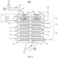
- the present invention relates to a multi-layered pyrolysis reactor (100) for the heat treatment of a rubber granulate (101), having a pyrolysis zone (180) and a gasification zone (182), wherein the reactor (100) comprises: (A) multiple hearths (130, 131), (B) a rotating central shaft (112), (C) rabble arms (140) provided with rabble tines (141) above each hearth (130, 131) and rotated by the rotating central shaft (112), the at least one rabble arm (140) and multiple hearths (130, 131) are configured to transfer the material radially along each hearth in an alternating inward and outward direction to affect a downward cascading of the material from one hearth to the next hearth therebelow, (D) an upper inlet (110) for the rubber granulate (101) configured to provide rubber granulate on the uppermost hearth, (E) a heating unit (170), wherein the heating unit (170) is configured to heat the material (rubber
- the pyrolysis zone is above the gasification zone.
- upper hearths are used for the pyrolysis and the lower hearts are used for the gasification.
- hearths 1 to 2 are used for the pyrolysis and hearths 3 to 6 are used for the gasification.
- the pyrolysis of rubber articles generally involves heating the rubber articles to temperatures, e.g., of at least 360 °C in the absence of oxygen in order to volatilize and decompose the rubber articles, producing oil, gas (pyrolysis gas), and char.
- temperatures e.g., of at least 360 °C in the absence of oxygen in order to volatilize and decompose the rubber articles, producing oil, gas (pyrolysis gas), and char.
- pyrolyzed carbon black-containing particulate is used for the expression “char” alternatively.
- the pyrolysis (a) and gasification (b) can be carried out as a continuous process.
- the pyrolysis (a) and gasification (b) are carried out in a multi-layered pyrolysis reactor, such as a multiple hearth furnace.
- a multi-layered pyrolysis reactor the pyrolysis is generally performed in the pyrolysis zone of the reactor and the gasification is performed in the gasification zone of the reactor. Accordingly, the entire process is a continuous process wherein the material after the pyrolysis is subjected directly to the gasification, i.e. both processes are carried out in one reactor.
- the reactor is usually configured that the material is subjected to the pyrolysis and then, to the gasification.
- the reactor comprises can comprise a steam inlet (174) provided at the lowermost hearth in the gasification zone (182). Accordingly, it is desired that the steam inlet is provided at the lowermost hearth of the reactor.
- the steam inlet can comprise multiple steam inlets. The multiple steam inlets can be evenly and circumferentially. It is intended that the provided steam can be evenly distributed in hearths.
- each hearth can define a separate reaction chamber.
- a separate reaction chamber is defined bas the space between two hearths.
- the lowermost hearth 6 and the hearth 5 defines a separate reaction chamber that is the separate reaction chamber of hearth 6.
- a hearth such as a specific hearth.
- the gaseous atmosphere in hearth 6 means the gaseous atmosphere in the separate reaction chamber of hearth 6.
- the pyrolysis zone can be the zone in which the heating unit (170) heats the material on each hearth to 360 to 740 °C, and/or gasification zone is the zone in which the burner(s) heat(s) the material on each hearth to 750 to 950 °C. As mentioned above, it is desired that the gasification zone is below the pyrolysis zone.
- the lowermost hearth can define the gasification zone, preferably in which the burner (173) for each hearth heats the material on each hearth to 750 to 950 °C.
- the two lowermost hearths can define the gasification zone, preferably in which the burner (173) for each hearth heats the material on each hearth to 750 to 950 °C.
- the three lowermost hearths can define the gasification zone, preferably in which the burner (173) for each hearth heats the material on each hearth to 750 to 950 °C.
- the four lowermost hearths can define the gasification zone, preferably in which the burner (173) for each hearth heats the material on each hearth to 750 to 950 °C.
- the reactor can comprise a steam outlet (175) that is positioned on the uppermost hearth for the gasification.
- the steam outlet (175) is preferably positioned below a hearth that has the opening (133) distal to the rotating central shaft (112). This allows a more efficient removal of the gasification gases.
- the hearths (130, 131) alternately and respectively can have an opening (132) proximal to the rotating central shaft (112) and an opening (133) distal to the rotating central shaft (112) so as to give the material to be treated a spiral path along the height of the furnace.
- a buffer gases outlet (176) can be provided in the buffer zone (181), preferably the buffer gases outlet (176) removes the gases in the buffer zone before the gases reaches the pyrolysis zone (180).
- a pyrolysis gases outlet (177) can be provided in the buffer zone (180), preferably the pyrolysis gases outlet (177) removes the gases in the pyrolysis zone (180).
- the rubber granulate comprises carbon black.
- Pyrolysis can be carried out in a reaction chamber and the oxygen content (in forms of O 2 ) in the reaction chamber should be less than 10000 ppm, preferably 1000 ppm, based on the total weight of the atmosphere in the reaction chamber. It is particularly preferred that no oxygen is present in the reaction chamber for the pyrolysis. It is particularly preferred that no oxygen is supplied into the reaction chamber for the pyrolysis.
- the reactor chamber for the pyrolysis can refer to the hearths in which the pyrolysis takes place.
- a pyrolysis gas is generally obtained.
- the pyrolysis gas stream can be used to at least partially heat the pyrolysis (a) process and/or the gasification (b) process.
- the pyrolysis gas comprises hydrogen.
- the hydrogen or the pyrolysis gas can be used as fuel for a burner to at least partially heat the pyrolysis (a) process and/or the gasification (b) process. Accordingly, a sustainable pyrolysis process can be achieved.
- the moving bed depth of the rubber granulate can be from 0.5 to 10 cm, preferably 1 to 5 cm, more preferably 1 to 3 cm, and most preferably 1.5 to 2.5 cm.
- the moving average bed depth of the rubber granulate can be from 0.5 to 10 cm, preferably 1 to 5 cm, more preferably 1 to 3 cm, and most preferably 1.5 to 2.5 cm.
- the moving bed depth of the rubber granulate in the pyrolysis zone can be from 0.5 to 10 cm, preferably 1 to 5 cm, more preferably 1 to 3 cm, and most preferably 1.5 to 2.5 cm.
- the bed average depth of the rubber granulate in the pyrolysis zone can be from 0.5 to 10 cm, preferably 1 to 5 cm, more preferably 1 to 3 cm, and most preferably 1.5 to 2.5 cm.
- the bed depth of the rubber granulate on each hearth in a multi-layered pyrolysis reactor can be 0.5 to 10 cm, preferably 1 to 5 cm, more preferably 1 to 3 cm, and most preferably 1.5 to 2.5 cm.
- the average bed depth of the rubber granulate on each hearth in a multi-layered pyrolysis reactor can be 0.5 to 10 cm, preferably 1 to 5 cm, more preferably 1 to 3 cm, and most preferably 1.5 to 2.5 cm.
- the bed depth of the rubber granulate on each hearth in a multi-layered pyrolysis reactor in the pyrolysis zone can be 0.5 to 10 cm, preferably 1 to 5 cm, more preferably 1 to 3 cm, and most preferably 1.5 to 2.5 cm.
- the average bed depth of the rubber granulate on each hearth in a multi-layered pyrolysis reactor in the pyrolysis zone can be 0.5 to 10 cm, preferably 1 to 5 cm, more preferably 1 to 3 cm, and most preferably 1.5 to 2.5 cm.
- the bed depth of the rubber granulate on each hearth in a multi-layered pyrolysis reactor in the gasification zone can be 0.5 to 10 cm, preferably 2 to 8 cm, more preferably 2 to 7 cm, and most preferably 2.5 to 5 cm.
- the average bed depth of the rubber granulate on each hearth in a multi-layered pyrolysis reactor in the gasification zone can be 0.5 to 10 cm, preferably 2 to 8 cm, more preferably 2 to 7 cm, and most preferably 2.5 to 5 cm.
- the moving bed depth of the rubber granulate on each hearth in a multi-layered pyrolysis reactor can be 0.5 to 10 cm, preferably 1 to 5 cm, more preferably 1 to 3 cm, and most preferably 1.5 to 2.5 cm.
- the moving average bed depth of the rubber granulate on each hearth in a multi-layered pyrolysis reactor can be 0.5 to 10 cm, preferably 1 to 5 cm, more preferably 1 to 3 cm, and most preferably 1.5 to 2.5 cm.
- the moving bed depth of the rubber granulate on each hearth in a multi-layered pyrolysis reactor in the pyrolysis zone can be 0.5 to 10 cm, preferably 1 to 5 cm, more preferably 1 to 3 cm, and most preferably 1.5 to 2.5 cm.
- the moving average bed depth of the rubber granulate on each hearth in a multi-layered pyrolysis reactor in the pyrolysis zone can be 0.5 to 10 cm, preferably 1 to 5 cm, more preferably 1 to 3 cm, and most preferably 1.5 to 2.5 cm.
- the moving bed depth of the rubber granulate on each hearth in a multi-layered pyrolysis reactor in the gasification zone can be 0.5 to 10 cm, preferably 2 to 8 cm, more preferably 2 to 7 cm, and most preferably 2.5 to 5 cm .
- the moving average bed depth of the rubber granulate on each hearth in a multi-layered pyrolysis reactor in the gasification zone can be 0.5 to 10 cm, preferably 2 to 8 cm, more preferably 2 to 7 cm, and most preferably 2.5 to 5 cm.
- the rabble arms (140) provided with rabble tines (141) are configured so that the desired bed depth is achieved. It is particularly preferred that the rabble arms (140) provided with rabble tines (141) are configured so that the desired moving bed depth is achieved. It is particularly preferred that the rabble arms (140) provided with rabble tines (141) are configured so that the desired moving average bed depth is achieved.
- the multiple hearths (130, 131) are configured so that the desired bed depth is achieved. It is particularly preferred that the multiple hearths (130, 131) are configured so that the desired moving bed depth is achieved. It is particularly preferred that the multiple hearths (130, 131) are configured so that the desired moving average bed depth is achieved.
- the rubber granulate with respect to the bed depth usually refer to the material/feedstock that is present on each hearth during the process.
- the residence time of the rubber granulate for the pyrolysis or for the gasification generally refers to the average residence time.
- the residence time and the average residence time for the pyrolysis or for the gasification refers to the residence time of the rubber granulate of the material is transported or that is moving.
- the residence time usually does not considered material that is not moving. For instance, material that refers to the dead bed depth in a MHF.
- the residence time of the rubber granulate for the pyrolysis (a) can be from 5 to 60 min, preferably 6 to 40 min, more preferably 6 to 25 min, and most preferably 7 to 15 min.
- the residence time of the rubber granulate for the pyrolysis (a) on each hearth of a multi-layered pyrolysis reactor can be from 1 to 20 min, preferably 2 to 15 min, more preferably 3 to 13 min, and most preferably 4 to 10 min.
- the residence time of the rubber granulate for the gasification (b) can be 20 min to 4 h, preferably 1 h to 2.5 h.
- the residence time of the rubber granulate for the gasification (b) on each hearth of a multiple hearth furnace can be from 7 to 60 min, preferably 30 to 40 min.
- the residence time of the material on each hearth of a multi-layered pyrolysis reactor can be from 10 to 60 min, preferably 10 to 40 min, more preferably 12 to 36 min, such as 10 to 15 min, 15 to 20 min, 30 to 40 min
- the number of rabble arms regulates the residence time of the material on each hearth of a multiple hearth furnace.
- the pyrolysis is carried out in rotary kiln and/or in a multi-layered pyrolysis reactor and the gasification is carried out in a fluidized bed reactor.
- the rubber granulate can be heated to the required temperature for the pyrolysis (a) by using an electrical heating unit.
- the electrical heating unit can heat an inert gas stream, such as a nitrogen gas stream, to the required temperature and the heated inert gas stream, such as a nitrogen gas stream, is subjected to the rubber granulate for the pyrolysis (a).
- the atmosphere during the pyrolysis for the rubber granulate can comprise nitrogen, preferably at least 20 vol.-% nitrogen, such as at least 25 vol.-% nitrogen, at least 30 vol.-% nitrogen, at least 40 vol.-% nitrogen, at least 50 vol.-% nitrogen, or at least 60 vol.-% nitrogen, based on the total volume of the atmosphere during the pyrolysis.
- the feedstock can be subjected with nitrogen (or nitrogen gas), such as heated nitrogen (or heated nitrogen gas), wherein the nitrogen (or nitrogen gas) preferably comprises at least 30 vol.-% nitrogen, such as at least 40 vol.-% nitrogen, at least 50 vol.-% nitrogen, at least 60 vol.-% nitrogen, at least 70 vol.-% nitrogen, or at least 80 vol.-% nitrogen, based on the total volume of the nitrogen (or nitrogen gas).
- nitrogen or nitrogen gas
- heated nitrogen or heated nitrogen gas
- the nitrogen (or nitrogen gas) preferably comprises at least 30 vol.-% nitrogen, such as at least 40 vol.-% nitrogen, at least 50 vol.-% nitrogen, at least 60 vol.-% nitrogen, at least 70 vol.-% nitrogen, or at least 80 vol.-% nitrogen, based on the total volume of the nitrogen (or nitrogen gas).
- the atmosphere during the pyrolysis for the rubber granulate can comprise hydrogen, preferably at least 10 vol.-% hydrogen, such as at least 20 vol.-% hydrogen, at least 25 vol.-% hydrogen, at least 30 vol.-% hydrogen, at least 40 vol.-% hydrogen, at least 50 vol.-% hydrogen, or at least 60 vol.-% hydrogen, based on the total volume of the atmosphere during the pyrolysis.
- the feedstock can be subjected with hydrogen (or hydrogen gas), such as heated hydrogen (or heated hydrogen gas), wherein the hydrogen (or hydrogen gas) preferably comprises at least 30 vol.-% hydrogen, such as at least 40 vol.-% hydrogen, at least 50 vol.-% hydrogen, at least 60 vol.-% hydrogen, at least 70 vol.-% hydrogen, or at least 80 vol.-% hydrogen, based on the total volume of the hydrogen (or hydrogen gas).
- hydrogen or hydrogen gas
- heated hydrogen or heated hydrogen gas
- the hydrogen (or hydrogen gas) preferably comprises at least 30 vol.-% hydrogen, such as at least 40 vol.-% hydrogen, at least 50 vol.-% hydrogen, at least 60 vol.-% hydrogen, at least 70 vol.-% hydrogen, or at least 80 vol.-% hydrogen, based on the total volume of the hydrogen (or hydrogen gas).
- the pyrolysis can be carried out by subjecting the rubber granulate with heated nitrogen to provide the desired temperature.
- the atmosphere during the pyrolysis for the rubber granulate can comprise less than 20 mol.-% H 2 O, such as less than 15 mol.-% H 2 O, less than 10 mol.-% H 2 O, less than 5 mol.-% H 2 O, less than 3 mol.-% H 2 O, less than 2 mol.-% H 2 O, or less than 1 mol.- % H 2 O, based on the total volume of the atmosphere during the pyrolysis.
- water is present during the pyrolysis but it is intended that the water content is as low as possible.
- water for the gasification or CO 2 for the gasification is removed from the atmosphere so that no water or no CO 2 is present during the pyrolysis. However, it is possible that residues of the water or CO 2 are still present.
- the atmosphere during the pyrolysis for the rubber granulate can comprise less than less than 5 mol.-% O 2 , such as less than 4 mol.-% O 2 , less than 2 mol.-% O 2 , less than 1 mol.-% O 2 , less than 0.5 mol.-% O 2 , less than 0.2 mol.-% O 2 , or less than 0.1 mol.- % O 2 , based on the total volume of the atmosphere during the pyrolysis.
- the rubber granulate comprises (or is) plastic granulate, and/or biomass-based granulate, preferably the rubber granulate comprises carbon black.
- the rubber granulate can be derived from a tire, preferably a pneumatic tire, a tire tread, a tire belt, a tire belt reinforcement, a tire carcass, a tire carcass reinforcement, a tire sidewall, tire inner liner, tire apex, tire shoulder, tire hump strip, tire chafer, a tire bead filler.
- the rubber granulate can be derived from a cable sheath, a tube, a drive belt, a conveyor belt, a roll covering, a shoe sole, a hose, a sealing member, a profile, a damping element, a coating or a colored or printed article.
- the rubber granulate is subjected to a size reducing step in order to obtain the desired particle size.
- the rubber granulate or the particulate carbon black-containing can be milled for instance using ultrasonic milling and electrical arc milling. Said milled rubber granulate or the rubber granulate can then be used as the rubber granulate for the pyrolysis (a).
- the volume average particle size x50 of the rubber granulate can be from 1 to 800 ⁇ m preferably 10 to 150 ⁇ m, more preferably 30 to 100 ⁇ m, and most preferably 35 to 60 ⁇ m, wherein the volume average particle size is preferably measured as described in the specification by dry measurement using laser diffraction.
- the volume average particle size x90 of the rubber granulate can be from 1 to 800 ⁇ m preferably 10 to 150 ⁇ m, more preferably 30 to 100 ⁇ m, and most preferably 35 to 60 ⁇ m, wherein the volume average particle size is preferably measured as described in the specification by dry measurement using laser diffraction.
- the volume average particle size x95 of the rubber granulate can be from 300 nm to 800 ⁇ m preferably 500 nm to 150 ⁇ m, more preferably 800 nm to 100 ⁇ m, and most preferably 1 to 20 ⁇ m, wherein the volume average particle size is preferably measured as described in the specification by dry measurement using laser diffraction.
- the volume average particle size x99 of the rubber granulate can be from 300 nm to 800 ⁇ m preferably 500 nm to 150 ⁇ m, more preferably 800 nm to 100 ⁇ m, and most preferably 1 to 20 ⁇ m, wherein the volume average particle size is preferably measured as described in the specification by dry measurement using laser diffraction.
- the particle size of the rubber granulate can be from 1 to 800 ⁇ m preferably 10 to 150 ⁇ m, more preferably 30 to 100 ⁇ m, and most preferably 35 to 60 ⁇ m, wherein the particle size is preferably measured as described in the specification by dry measurement using laser diffraction.
- the particle size of the rubber granulate can be less than 800 ⁇ m preferably less than 500 ⁇ m, more preferably less than 300 ⁇ m, and most preferably less than 200 ⁇ m, wherein the particle size is preferably measured as described in the specification by dry measurement using laser diffraction.
- the particle size distribution can be determined by dry measurement with the measurement system from Sympatec GmbH (Germany) consisting of VIBRI: conveyor unit (by vibration); RODOS: compressed air dispersion; and HELOS BR: measuring unit, laser diffraction.
- VIBRI conveyor unit (by vibration); RODOS: compressed air dispersion; and HELOS BR: measuring unit, laser diffraction.
- VIBRI conveyor unit (by vibration); RODOS: compressed air dispersion; and HELOS BR: measuring unit, laser diffraction.
- VIBRI conveyor unit (by vibration);
- RODOS compressed air dispersion
- HELOS BR measuring unit, laser diffraction
- the obscuration range is controlled by the feeding rate with automatic adjustment and the hopper gap in the range of 5-15% using an integral factor of 0.2.
- the dispersing air pressure is set to 3 bar.
- Reported values volume distribution
- At least 70 wt.-%, preferably at least 80 wt.-%, more preferably at least 90 wt.-%, most preferably at least 98 wt.-%, of the rubber granulate has a particle size of more than 2 mm, wherein the particle size is measured according to ASTM D 1511-12 (2017).
- At least 50 wt.-%, preferably at least 60 wt.-%, more preferably at least 70 wt.-%, most preferably at least 80 wt.-%, of the rubber granulate has a particle size of more than 2 to 2.8 mm, wherein the particle size is measured according to ASTM D 1511-12 (2017) using an additional U.S. Standard Sieves or equivalent, conforming to Specification ASTM E11, Sieve Nos. 7, having openings of 2800 ⁇ m.
- the sieves shall be 25 mm in height and 200 mm in diameter.
- the rubber granulate can comprise ash (or has an ash content), wherein ash comprise metal, metal compounds, silicon, oxygen, sulphur and/or silica, preferably metal comprises zinc, silicon, calcium, cobalt, manganese, potassium, aluminum, and/or iron.
- the rubber granulate can comprise zinc, preferably zinc oxide.
- the zinc is generally derived from a tire based feedstock used for the vulcanization of the rubber article.
- the rubber granulate can have a zinc content in a range of from 2.0 to 6.0 mass %, preferably from 2.5 to 5.5 mass %, more preferably from 3.0 to 5.0 mass %, most preferably from 3.5 to 4.5 mass %, wherein the zinc content is based on the total mass of rubber granulate and wherein the zinc content is preferably determined according to Inductively Coupled Plasma Optical Emission Spectrometry (ICP-OES), more preferably the zinc content is determined as described in the specification.
- ICP-OES Inductively Coupled Plasma Optical Emission Spectrometry
- the analysis of the Zn content can be conducted following method A in ASTM D8371-20 using an ICP-OES (Spectro Arcos III) from SPECTRO Analytical Instruments GmbH (Germany) and a microwave (turboWAVE inert) from MLS Mikrowellen-Labor-Systeme GmbH (Germany).
- ICP-OES Spectro Arcos III
- microwave turboWAVE inert
- MLS Mikrowellen-Labor-Systeme GmbH Germany
- 0.3-0.4 g of the material was weighted into a microwave tube with a capacity of 15 cm 3 and wetted with 1 ml of pure water ( ⁇ 0.055 ⁇ S/cm). Afterward, 10 cm 3 of concentrated nitric acid ( ⁇ 65 %) was added to the tube and treated in the microwave. The sample was then measured with ICP-OES.
- the rubber granulate can have a silicon (Si) content in a range of from 1.0 to 5.0 wt.-%, preferably from 1.8 to 4.5 wt.-%, more preferably from 2.0 to 4.0 wt.-%, wherein the wt.-% is based on the total weight of the rubber granulate and wherein the silicon content is preferably determined by to Inductively Coupled Plasma Optical Emission Spectrometry (ICP-OES), more preferably the silicon content is determined as described in the specification.
- ICP-OES Inductively Coupled Plasma Optical Emission Spectrometry
- the analysis of the Si content was conducted using an ICP-OES (iCAP 6300) from Thermo Fisher (USA) and a microwave (turboWAVE inert) from MLS Mikrowellen-Labor-Systeme GmbH (Germany).
- ICP-OES ICP-OES
- a microwave turboWAVE inert
- MLS Mikrowellen-Labor-Systeme GmbH Germany
- a combination of concentrated nitric acid ( ⁇ 65 %) and concentrated hydrofluoric acid ( ⁇ 49%) (usually in a volume ratio of 1:1) with microwave treatment was used to completely digest the sample with microwave treatment.
- the digested sample is diluted with distilled water to a suitable concentration.
- the sample was measured with ICP-OES, whereby the device is equipped with a sample introduction kit suitable for HF.
- the silica (or silicon in form of silica) is typically embedded in the carbon black of the rubber granulate, attached to the carbon black of the rubber granulate, attached on the surface of the carbon black of the rubber granulate, and/or associated in the carbon black of the rubber granulate.
- the silica (or silicon in form of silica) is typically embedded in the carbon of the rubber granulate, attached to the carbon of the rubber granulate, attached on the surface of the carbon of the rubber granulate, and/or associated in the carbon of the rubber granulate.
- the gasification atmosphere in which the material (such as the material after the pyrolysis) is treated can comprise 20 to 100 mol-% H 2 O and/or CO 2 , preferably 30 to 100 mol -% H 2 O and/or CO 2 , more preferably 40 to 90 mol-% H 2 O and/or CO 2 , most preferably 50 to 80 mol-% H 2 O and/or CO 2 , based on the total number of moles of the gasification atmosphere in which the material (such as the material after the pyrolysis) is treated.
- a high hydrogen containing atmosphere can be obtained by using a hydrogen burner.
- the material (such as the material after the pyrolysis) is subjected with steam for the gasification.
- the steam can be used to provide the required temperature for the gasification.
- a gas comprising or consisting of H 2 O can be preheated to a temperature of 200 °C to 950 °C, such as 730 °C to 950 °C, 730 °C to 910 °C, 730 °C to 900 °C, 740 to 890 °C, 740 °C to 860 °C, or 790 to 850 °C.
- the steam can be preheated to a temperature of 200 °C to 950 °C, such as 730 °C to 950 °C, 730 °C to 910 °C, 730 °C to 900 °C, 740 to 890 °C, 740 °C to 860 °C, or 790 to 850 °C.
- a heat exchanger can exchange heat from another gas stream, such as the pyrolysis gas stream, the gasification gas stream and/or the buffer gas stream to the steam.
- the material such as the material after the pyrolysis, generally refers to the pyrolyzed carbon black-containing particulate.
- the pyrolyzed carbon black-containing particulate can be heated to the required temperature for the gasification (b) by using a burner, preferably the fuel for the burner is hydrogen or natural gas, preferably hydrogen.
- the burner for the gasification (b) can be a hydrogen burner.
- Hydrogen for the burner has several advantages. First, the pyrolysis gas typically comprises hydrogen so that the pyrolysis gas can be used directly as the fuel or the hydrogen can be separated from the pyrolysis gas and said hydrogen is used as fuel. In addition, a hydrogen burner can be used to generate the steam required for the gasification process.
- the required H 2 O for the gasification as well as the required heat can be provided by at least one hydrogen burner.
- the rubber granulate can be milled before the gasification step, and/or wherein the obtained treated carbon black is milled after the gasification step. For instance, using ultrasonic milling and/or electrical arc milling and/or jet milling.
- the gasification can be carried out for 1 min to 10 h, preferably 10 min to 5 h, more preferably 20 min to 3 h, even more preferably 30 min to 2 h, and most preferably 40 min to 1.5 h.
- the method can be carried out in a multiple hearth furnace and the pyrolysis is carried out on a hearth above a hearth for the gasification, wherein H 2 O (or steam) used for the gasification is removed from the multiple hearth furnace before entering a hearth for the pyrolysis.
- carbon blacks can in particular contain as impurities organic compounds that have a skeleton with a polycyclic aromatic structure, which are commonly referred to as polycyclic aromatic hydrocarbons (PAHs).
- PAHs are believed to be harmful to the health and environment as for example discussed in Sudip K. Samanta, Om V. Singh and Rakesh K. Jain: "Polycyclic aromatic hydrocarbons: environmental pollution and bioremediation", TRENDS in Biotechnology, Vol. 20, No. 6, Jun. 2002, pages 243-248 . Therefore, the PAH content of carbon blacks is subject to increasingly demanding customer needs and official regulations for applications such as use in food or beverage contact situations, pharmaceuticals, cosmetics, or the manufacture of toys and articles for children.
- the American Food and Drug Administration has limited the total PAH content of high purity furnace blacks in goods with food contact to 0.5 ppm (cf. U.S. Code of Federal Regulations (CFR) 21 Sec.178.3297), whereby the PAH content is defined as the sum of 22 PAH compounds (PAH22 content).
- the measurement of the transmittance at 425 nm in toluene measured according to ASTM D 1618-18 against toluene can still reveal that a significant amount of impurities is still present (low transmittance).
- a high transmittance at 425 nm, such as more than 90 % does not mean that only a negligible amount of organic impurities is present on the respective carbon black.
- the transmittance at lower wavelengths, such as 300 nm or 355 nm, may reveal that the carbon black comprises a high amount of organic impurities.
- the treated carbon black can have a transmittance of at least 80 %, preferably at least 85 %, more preferably at least 90 %, even more preferably at least 95 %, most preferably at least 98 % wherein the transmittance at 425 nm in toluene is measured according to ASTM D 1618-18 against toluene.
- the treated carbon black can have a transmittance of at least 80 %, preferably at least 85 %, more preferably at least 90 %, even more preferably at least 95 %, most preferably at least 98 % wherein the transmittance at 355 nm in toluene is measured according to ASTM D 1618-18 against toluene, wherein the transmittance is measured at 355 nm instead of 425 nm.
- the treated carbon black has a transmittance of at least 80 %, preferably at least 85 %, more preferably at least 90 %, even more preferably at least 95 %, most preferably at least 98 % wherein the transmittance at 425 nm in toluene is measured according to ASTM D 1618-18 against toluene, and a transmittance of at least 80 %, preferably at least 85 %, more preferably at least 90 %, even more preferably at least 95 %, most preferably at least 98 % wherein the transmittance at 355 nm in toluene is measured according to ASTM D 1618-18 against toluene, wherein the transmittance is measured at 355 nm instead of 425 nm, and a transmittance of at least 80 %, preferably at least 85 %, more preferably at least 90 %, even more preferably at least 95 %, most preferably at least 98 % wherein the transmittance at 300
- MOAH and MOSH/POSH values indicate the organic impurities of the carbon black. Again, the mere pyrolysis to obtain rCB (heat treatment) does not sufficiently reduce the organic impurities measured according to MOAH and MOSH/POSH.
- the treated carbon black can have a MOAH value of below 500 mg/kg, preferably below 300 mg/kg, more preferably below 250 mg/kg, and most preferably below 200 mg/kg, determined as described in the specification.
- the treated carbon black can have a MOSH/POSH value of below 900 mg/kg, preferably below 500 mg/kg, more preferably below 300 mg/kg, even more preferably below 150 mg/kg and most preferably below 100 mg/kg, determined as described in the specification.
- the treated carbon black can have an iodine adsorption number of 30 to 80 mg/g, preferably 40 to 70 mg/g, more preferably 45 to 65 mg/g, the iodine adsorption number is measured according to ASTM D1510-17.
- the treated carbon black can have a BET surface area determined according to ASTM D6556-17 in a range from 15 to 500 m 2 /g, preferably from 30 to 300 m 2 /g, more preferably from 40 to 250 m 2 /g, even more preferably from 50 to 200 m 2 /g, most preferably from 60 to 150 m 2 /g.
- BET surface area determined according to ASTM D6556-17 of the treated carbon black is higher than the BET surface area determined according to ASTM D6556-17 of the rubber granulate.
- the obtained treated carbon black after the gasification can have (a) a BET surface area determined according to ASTM D6556-17 in a range from 40 to 100 m 2 /g, preferably from 50 to 80 m 2 /g, more preferably 55 to 70 m 2 /g, and a compressed oil absorption number (COAN) measured according to ASTM D3493-16in a range from 30 to 200 mL/100 g, preferably from 40 to 150 mL/100 g, more preferably from 50 to 120 mL/100 g, even more preferably from 55 to 110 mL/100 g, most preferably from 60 to 90 mL/100 g, (b) a BET surface area determined according to ASTM D6556-17 in a range from 10 to 100 m 2 /g, preferably from 20 to 90 m 2 /g, more preferably 25 to 80 m 2 /g, and a compressed oil absorption number (COAN) measured according to ASTM D3493-16in a range from 30 to
- the treated carbon black can have a volatile content measured at 950°C of 0.1 to 10 wt.-%, such as 0.3 to 10 wt.-%, 0.5 to 10 wt.-%, 0.7 to 5 wt.-%, 0.8 to 4 wt.-%, 0.9 to 3 wt.-%, 1 to 2.5 wt.-%, 1.1 to 2.3 wt.-%, 1.2 to 2.2 wt.-%, 1.3 to 2.1 wt.-%, 1.4 to 2 wt.-%, 1.5 to 1.9 wt.-%, or 1.6 to 1.8 wt.-%.
- the volatile content can be measured as described in the specification.
- the obtained treated carbon black can be milled. For instance, using mechanical (impact) milling, jet milling, ultrasonic milling and/or electrical arc milling.
- the desired particle sizes can be obtained after milling the obtained treated carbon black. Accordingly, the mentioned particle sizes and particle size distributions of the obtained recovered carbon black obtained after the milling.
- volume average particle size of the carbon black-containing feedstock is higher than the volume average particle size of the obtained treated carbon black, wherein the volume average particle size is preferably measured as described in the specification by dry measurement using laser diffraction.
- the volume average particle size x99 of the obtained treated carbon black can be from 0.3 to 50 ⁇ m preferably 0.5 to 50 ⁇ m, more preferably 0.8 to 20 ⁇ m, and most preferably 1 to 10 ⁇ m, wherein the volume average particle size is preferably measured as described in the specification by dry measurement using laser diffraction.
- the treated carbon black can have an ash content in a range of from 3 to 50 wt.- %, preferably from 10 to 40 wt.-%, more preferably from 10 to 30 wt.-%, most preferably from 15 to 25 wt.-%, wherein the wt.-% is based on the total weight of the treated carbon black and wherein the ash content is determined according to ASTM D 1506-15 at 550 °C, 16 h. It is desired that the ash content determined according to ASTM D 1506-15 at 550 °C, 16 h, of the treated carbon black is higher compared to the ash content determined according to ASTM D 1506-15 at 550 °C, 16 h, of the rubber granulate. It is believed that the rubber granulate is de-coked during the gasification so that the overall carbon content is lower in the treated carbon black so that the relative ash content based on the total weight of the treated carbon black is higher.
- the treated carbon black can have a cumulative pore volume for pore sizes of 0.3 to 1.5 nm of 0.015 to 0.050 cm 3 /g, preferably 0.018 to 0.045 cm 3 /g, more preferably 0.020 to 0.040 cm 3 /g, even more preferably 0.021 to 0.035 cm 3 /g, and most preferably 0.023 to 0.034 cm 3 /g, wherein the cumulative pore volume is determined as mentioned in the specification.
- the treated carbon black can have a cumulative pore volume for pore sizes of 0.3 to 0.75 nm of 0.008 to 0.035 cm 3 /g, preferably 0.009 to 0.025 cm 3 /g, more preferably 0.0101 to 0.020 cm 3 /g, even more preferably 0.011 to 0.0185 cm 3 /g, and most preferably 0.011 to 0.015 cm 3 /g, wherein the cumulative pore volume is determined as mentioned in the specification.
- the at least one plastic material may comprise a thermoplastic polymer, a thermosetting polymer, a thermoplastic elastomer, preferably low and high density polyethylene and polypropylene, polyvinyl chloride, melamine-formaldehyde resin, phenolic resin, epoxy resin, polyamide, polyester, polyoxymethylene, polymethyl methacrylate, polycarbonate, polystyrene, polyurethane, polyphenylene oxide, polysiloxane, polyacryloamide, polyaryletherketone, polysulfone, polyetherimide, acrylonitrile styrene acrylate or acrylonitrile butadiene styrene polymer and mixtures or co-polymers of any of the foregoing.
- the multi-layered pyrolysis reactor comprises an upper inlet (110) for the rubber granulate (101) to be treated.
- a screw conveyer (111) is shown that transfers rubber granulate (101) to the upper inlet (110) and onto the upper hearth of the reactor (100).
- the screw conveyer (111) is driven by a motor.
- the reactor further comprises multiple rabble arms (140) provided with rabble tines (141) above each hearth (130, 131) and rotated by the rotating central shaft (112), said hearths (130, 131) alternately and respectively having an opening (132) proximal to the rotating central shaft (112) and an opening (133) distal to the rotating central shaft (112) so as to give the material to be treated a spiral path along the height of the furnace.
- the multiple rabble arms (140) and hearths (130, 131) are configured to transfer the material radially along each hearth in an alternating inward and outward direction to affect a downward cascading of the material from one hearth to the next hearth therebelow.
- the electrical heating unit (170) that is inside the reaction chamber can be an electrical heating element that is positioned above the rabble arms in the pyrolysis zone (180). In other words, it is intended that the electrical heating unit (170) is positioned above each rabble arms on each hearth. Said electrical heating unit (170) can provide the necessary temperature for the pyrolysis.
- an electrical heating unit (170) is provided outside the reactor.
- a first inert gas stream (171), such as nitrogen, is subjected to an electrical heater to obtain a heated inert gas stream, such as a heated nitrogen stream.
- a second inert gas stream (172), such as nitrogen, is connected to the heated nitrogen stream.
- the second inert gas stream (172) can be used to precisely control the temperature of the inert gas stream subjected into the reactor (100), i.e. reaction chamber.
- the electrical heating unit (170) comprises an electrical heating unit (170) that is inside the reaction chamber and an electrical heating unit (170) that is positioned outside the reactor.
- the numbering of the hearths starts with the uppermost hearth.
- the third hearth in FIG. 1 is an optional buffer hearth that should not be separately heated.
- the reactor (100) further comprises a burner (173) for each hearth in the gasification zone (182).
- a burner (173) is present on each of the four lowermost hearths.
- Each burner (173) is supplied with fuel and oxygen. It is specifically preferred that hydrogen is the fuel (i.e. oxyhydrogen).
- hydrogen is the fuel (i.e. oxyhydrogen).
- a natural gas such as methane, ethane or propane, can be used as fuel as well. It is possible that multiple burners (173) for each hearth in the gasification zone (182) are disposed circumferentially around the interior of said reaction chamber.
- the number rabble arms (640) comprising rabble tines (641) is not specifically limited but the number of rabble arms (640) regulates the residence time of the material on each hearth. It is preferred that the number of rabble arms (640) provided with rabble tines (141) above each hearth (630, 631) is from 1 to 5, preferably 1 to 4, such as 1, 2, 3 or 4. It should be noted that the number of rabble arms (640) specifically relate to the rabble arms (640) comprising rabble tines (141). It is possible that the reactor comprises further rabble arms (640) without rabble tines.
- FIG. 2 a further MHF reactor is shown.
- the reactor has two pyrolysis hearths in the pyrolysis zone (180), two buffer hearths in the buffer zone (181), and three gasification hearths in the gasification zone (182).
- Steam outlets (175) are shown that are positioned below a hearth that has the opening (133) distal to the rotating central shaft (112). Accordingly, it is possible improve the efficiency of the removal of steam before entering the buffer zone (181) and/or the pyrolysis zone (180).
- the multi-layered pyrolysis reactor (100) according to anyone of aspects 1 or 2, wherein the multi-layered pyrolysis reactor (100) is a multiple hearth furnace (100).
- the multi-layered pyrolysis reactor (100) according to anyone of the preceding aspects, wherein the reactor comprises 2 to 20 hearths, preferably 4 to 15 hearths, more preferably 6 to 12 hearths, even more preferably 6 to 10 hearths, and most preferably 7 to 8 hearths.
- pyrolysis zone is the zone in which the heating unit (170) heats the material on each hearth to 360 to 740 °C
- gasification zone is the zone in which the burner(s) heat(s) the material on each hearth to 750 to 950 °C.
- thermolysis reactor 100 according to anyone of the preceding aspects, wherein the heating unit (170) is an electrical heating unit (170), preferably wherein pyrolysis zone is the zone in which the electrical heating unit (170) heats the material on each hearth to 360 to 740 °C, and/or gasification zone is the zone in which the burner(s) heat(s) the material on each hearth to 750 to 950 °C.
- the heating unit (170) is an electrical heating unit (170)
- pyrolysis zone is the zone in which the electrical heating unit (170) heats the material on each hearth to 360 to 740 °C
- gasification zone is the zone in which the burner(s) heat(s) the material on each hearth to 750 to 950 °C.
- heating unit (170) is a microwave heating unit, wherein a microwave heating unit is present for each hearth in the pyrolysis zone (180), configured to heat the material to 360 to 740 °C.
- the multi-layered pyrolysis reactor (100) according to anyone of the preceding aspects, wherein the reactor comprises a steam outlet (175) on the uppermost hearth of the buffer zone (181) and/or on the uppermost hearth of the gasification zone (182).
- the multi-layered pyrolysis reactor (100) according to anyone of the preceding aspects, wherein the reactor comprises a steam outlet (175) that is configured to remove steam before the steam reaches the pyrolysis zone (180).
- each burner (173) for each hearth in the gasification zone (182) is a hydrogen-oxygen burner.
- Example 4A the rubber granulate 1 was subjected to a pyrolysis reaction without a subsequent gasification. Accordingly, hearths 3 to 6 were not heated and no steam was subjected into the reactor.
- a fuel burner was used for the pyrolysis.
- an electrical heating unit or a microwave heating unit can be used instead of a fuel burner. It is believed that an electrical heating unit and/or a microwave heating unit for the pyrolysis and a fuel burner the subsequent gasification result in a similar treated product.
- the utilization of an electrical heating unit and/or a microwave heating unit for the pyrolysis has further advantages for the process. No reaction water or CO 2 /CO derived from the combustion of fuel are present.
- Table 1 Process conditions used for the MHF process. Hearth Number of used rabble arms Residence time / min Temp. / °C Subjected steam / kg h -1 Bed depth (moving bed depth) / cm Dead bed depth / cm
- Example 1A 2A 3A Air / Nm 3 /h 90 102 59 NG / Nm 3 /h 10 11.48 6.2 Steam flow / kg h -1 40 10 10 Production Rate kg/h 7.56 7.15 8.78 Feeding rate kg/ h 23.76 24.5 23.76 Pyrolysis Yield / wt.-% 43 43 43 De-coking Yield / wt.-% 73 69 85 Total solid Yield / wt.-% 31 30 37 Calc. removed carbon / wt.-% 27 31 15
- the pyrolysis yield is the yield after the pyrolysis in the first two hearths.
- the gasification process was omitted and the yield after the pyrolysis was noted.
- the de-coking yield is the yield after the gasification based on the feedstock subjected to the gasification. Accordingly, Example 1A has a yield of 73 wt.-% based on the feedstock subjected to the gasification so that 27 wt.-% of carbon was converted to gas. It is believed that the coke present in the feedstock has a higher reactivity compared to carbon black. If the temperature during the gasification is below 950 °C, the coke is selectivity converted instead of the carbon black. At higher temperatures, the selectivity decreases. Accordingly, in Example 1A, it is believed that the calc. removed carbon of 27 wt.-% is coke.
- Example 1A Example 2A
- Example 3A Example 4A Toluene transmittance 1 at 300 nm 1 / % 0.0 9.5 94.5 94.25 88.84 0.03 Toluene transmittance 1 at 355 nm 1 / % 18.4 89.5 99.2 99.50 97.97 0.75 Toluene transmittance 2 at 425 nm 2 / % 79.2 99.7 99.9 99.76 100 28.82 Ash content 3 / wt.-% 23.9 22.8 31.9 30.7 30.1 27.7 STSA 4 / m 2 g -1 60.9 58.1 63.4 64.3 56.1 47 BET 5 / m 2 g -1 72.4 71.3 79.8 82.5 66.4 53.3 C / wt.% 6 n.D.
- the ash content for the treated carbon black in the MHF is higher than for the two commercial rCBs. This is due to the fact that additional steam and a treatment at higher temperatures was used in the MHF in order to de-coke the material. This causes some of the carbon to react with the steam to form carbon monoxide. Consequently, a reduced carbon content results in a higher ash content.
- the treated carbon black obtained from the tests in the MHF has higher transmission values than two commercial rCBs. It can therefore be concluded that the rCB produced in the reactor is loaded with fewer organic, toluene extractable contaminants (such as aliphatics and small aromatics) than the two commercial rCBs.
- Example 4A reveals that the H:C atomic ratio is significantly higher than the H:C atomic ratio of Examples 1A, 2A and 3A. This is an indication that contaminants are present on the carbon black obtained in Example 4A which are removed following de-coking.
- a high cumulative pore volume (microporosity) for carbon black that is recycled from a carbon black-containing feedstock is desired.
- the commercial recovered carbon blacks generally have a low cumulative pore volume. These pores are important for the applicability of the carbonaceous filler in a rubber matrix, as the high surface area and magnitude of Van Der Waal interactive forces in these small pores commonly act as sites for chemical bonding. In carbon black, these pores can exist either within or between primary particles. In recovered carbon black, coke deposition during the pyrolysis process would likely occur in these microporous regions, reducing the overall microporous surface area and microporous volume. This is anticipated to have a negative impact on in-application tests.
- the gasification additionally improves the microporosity of the obtained treated carbon black as can be seen from examples 1A to 3A compared to 4A.
- the gasification of the coke causes a more microporous surface, which is anticipated to improve in rubber application processes.
- Adsorption and desorption isotherms for CO 2 at 273 K were collected between the pressure range (P/P0) of 0.05 and 1 on a Quantachrome Autosorb iQ3 Gas Sorption Analyser (Software: Model 7 ASiQWin Version: 5.21). Briefly, 0.4 g of carbon sample was placed in a de-gassed sample cell and was de-gassed at 300 degrees Celsius under vacuum to remove adsorbed gases and moisture from the sample surface. The degassed sample was re-weighed and loaded onto the analysis station, where it was exposed to a further degas step under helium, followed by gaseous CO 2 at close to condensation temperatures (273 K) within the pressure range of 0.01 - 1 bar.
- the carbon mass fraction, hydrogen fraction mass, nitrogen mass fraction and sulfur mass fraction are measured using an elemental analyser with thermal conductivity and infrared detector.
- the analyser is a device for the fully automatic and quantitative analysis of the above elements.
- the combustion tube is brought to a temperature of 1100 °C and the reduction tube to 850 °C.
- a blank measurement is conducted.
- the carbon peak area should have a value ⁇ 50, the hydrogen peak area a value ⁇ 300, the nitrogen peak area a value ⁇ 50 and the sulphur peak area a value ⁇ 350. Otherwise, the individual adsorption columns are heated and then empty measurements are started again.
- the daily factor is measured.
- 3 mg of sulphanilamide and 3 mg of low-level standard e.g. carbon black standard
- 3 mg of sulphanilamide and 3 mg of low-level standard are weighed into each of 8 tin capsules. After weighing out the respective sample, it is placed in the capsule press, overlaid with helium for 35 s and then cold-sealed. Subtracting the blank value, the known theoretical element concentration of the standard samples is put in relation to the actually calculated element concentration. This results in the daily factor, which must be between 0.9 - 1.1. If this is not the case, these measurements should be repeated with newly opened standards. Otherwise, a new calibration must be carried out according to the manufacturer's instructions.
- the combustion tube is enriched with O 2 .
- the elements C, H, N and S burn to form CO 2 , H 2 O, NOx, SO 2 and SO 3 .
- Halogen bound in the sample reacts to form volatile halogen compounds.
- there are WO 3 granules in the combustion tube that provide further O 2 as a catalyst, prevent the formation of nonvolatile sulphates and bind interfering alkali and alkaline earth elements.
- the carrier gas stream is fed into the reduction tube with Cu filling. Nitrogen oxides (NOx) are completely reduced to N 2 at the copper contact. SO 3 is reduced to SO 2 . Volatile halogen compounds are bound to the silver wool.
- N 2 is not adsorbed and enters the thermal conductivity detector as the first measuring component, CO 2 , H 2 O and SO 2 are adsorbed on the respective adsorption columns.
- the adsorption columns are brought to desorption temperature, so that CO 2 , then H 2 O as carrier gas enters the thermal conductivity detector and SO 2 enters the infrared detector.
- the detector delivers an electrical signal which is digitised and integrated.
- the measurement signal is recorded as a function of time and displayed as an integral value.
- the absolute element content of the sample is calculated from this integral value of the individual measurement peaks and the calibration factors.
- an electrical signal is transmitted from the thermal conductivity detector (WLD) of the elemental analyser to a micro controller and then displayed as an integral value. From the integral value of the measurement peaks and the calibration factor, the absolute element content of the sample is concluded.
- WLD thermal conductivity detector
- the pyrolysis tube is heated to a temperature of 1050°C.
- a blank measurement is conducted.
- the oxygen peak area should have a maximum value of 200. If the blank value is not below 200, CO adsorption column should be heated up (260 °C, CO desorption 150 °C). After the blank values have been successfully measured, the mean value of the blank value areas is calculated.
- the daily factor is measured.
- 3 mg of acetanilide are weighed into each of 8 tin capsules. After weighing out the respective sample, it is placed in the capsule press, overlaid with helium for 35 s and then cold-sealed. Subtracting the blank value, the known theoretical element concentration of the standard samples is put in relation to the actually calculated element concentration. This results in the daily factor, which must be between 0.9 - 1.1. If this is not the case, these measurements should be repeated with newly opened standards. Otherwise, a new calibration must be carried out according to the manufacturer's instructions.
- tin capsules each containing 5 mg ⁇ 1 mg of the desired measured component, such as rubber granulate, are weighed. After weighing the respective samples, they are placed in the capsule press, covered with helium for 35 s and then cold welded. The samples are then measured.
- the desired measured component such as rubber granulate
- the fraction containing MOSH/POSH is separated from the fraction containing MOAH using an online HPLC/GC coupling on a silica gel phase.
- MOSH Saturated hydrocarbons from mineral oil. These consist of paraffins (open-chain hydrocarbons) and naphthenes (cyclic hydrocarbons), which are usually highly alkylated and either come directly from petroleum or were formed through the hydrogenation of aromatics and other conversion processes during refining.
- POSH Saturated hydrocarbons, which occur as oligomers from polyolefins (e.g. polyethylene, polypropylene) and related products in plastics and can be transferred to food. The MOSH and POSH hydrocarbons are not separated.
- MOAH Mineral oil aromatic hydrocarbons
- the fiberglass or glass extraction sleeve required to extract the samples is cleaned beforehand. To do this, the sleeve is pre-extracted with cyclohexane for at least 24 hours (Soxhlet extraction with N 2 flushing of the condenser). The required glass wool and the extraction devices are also pre-extracted or cleaned with cyclohexane.
- the cleaned sleeve is extracted with cyclohexane after drying.
- This extract is processed in the same way as the sample, i.e. by adding 20 ⁇ L ISTD solution (see tables below) and concentrating the solvent to a final volume of 2.0 mL.
- 3 g of carbon black are weighed into the extraction sleeve.
- 20 ⁇ L ISTD solution specified before extraction
- the sleeve is closed with cleaned glass wool.
- the Soxhlet extraction is then carried out for 24 hours with N 2 flushing of the condenser with cyclohexane.
- the concentration is carried out on a rotary evaporator/ Büchi Syncore to a final volume of 1 mL. 1.0 mL Cyclohexane is then added to the extract and the glass surface is rinsed with the solvent. For measurement, 50 ⁇ L of this solution is injected into the Online-HPLC/GC-FID system.
- the fractions of MOSH/POSH and MOAH separated on the normal phase HPLC are transferred to the gas chromatograph.
- the individual fractions are then chromatographically separated and quantified.
- the quantitative calculation of the MOSH/POSH and MOAH fractions is carried out using the peak areas of the Humps or Unresolved Complex Mixture (UCM) for each fraction using the standards via their response factors. Due to the detection using FID, the response factors of the saturated hydrocarbons and the aromatic hydrocarbons are set equal.
- MOSH/POSH fraction this is usually Bicyclohexyl (CyCy) and for the MOAH fraction it is tri - tert -butylbenzene (TBB) or 2-methylnaphthalene. If coelutions are recognizable, another ISTD is used as an alternative for quantification.
- the individual fractions, belonging to the boiling point ranges are also quantified using the internal standards and included as results in the report.
- Tables 4i and 4ii ISTD composition (internal standard solution)
- Table 4i MOSH fraction (in elution order): Substance CAS No. Abbreviation Concentration n- Undecane [1120-21-4] (C11) 300 ⁇ g / mL Cyclohexylcyclohexane or Bicyclohexyl [92-51-3] (CyCy) 300 ⁇ g/mL n- Tridecanes [629-50-5] (C13) 150 ⁇ g / mL 5-alpha-Cholestane [481-21-0] (cho) 600 ⁇ g / mL Table 4ii: MOAH fraction (in elution order): Substance CAS No.
Landscapes
- Chemical & Material Sciences (AREA)
- Engineering & Computer Science (AREA)
- Oil, Petroleum & Natural Gas (AREA)
- Organic Chemistry (AREA)
- Materials Engineering (AREA)
- Combustion & Propulsion (AREA)
- Mechanical Engineering (AREA)
- General Engineering & Computer Science (AREA)
- Chemical Kinetics & Catalysis (AREA)
- General Chemical & Material Sciences (AREA)
- Separation, Recovery Or Treatment Of Waste Materials Containing Plastics (AREA)
Priority Applications (11)
| Application Number | Priority Date | Filing Date | Title |
|---|---|---|---|
| EP24150497.6A EP4582511A1 (de) | 2024-01-05 | 2024-01-05 | Kautschuk-russ herstellung in einem pyrolyse und vergasung mehretagenofen |
| EP24192594.0A EP4582512A1 (de) | 2024-01-05 | 2024-08-02 | Herstellung von kautschukruss durch pyrolyse und und vergasung von kautschuk in einem etagenofen |
| EP24192586.6A EP4582378A1 (de) | 2024-01-05 | 2024-08-02 | Vergasung von wiedergewonnenem russ |
| EP24192597.3A EP4582188A1 (de) | 2024-01-05 | 2024-08-02 | Vergasung von wiedergewonnenem russ |
| PCT/EP2025/050039 WO2025146453A1 (en) | 2024-01-05 | 2025-01-02 | Gasification of recovered carbon black |
| PCT/EP2025/050040 WO2025146454A1 (en) | 2024-01-05 | 2025-01-02 | Carbon black production from rubber in a multiple hearth pyrolysis and gasification furnace |
| PCT/EP2025/050043 WO2025146455A1 (en) | 2024-01-05 | 2025-01-02 | Pyrolysis and gasification of rubber granulate |
| PCT/EP2025/050035 WO2025146450A1 (en) | 2024-01-05 | 2025-01-02 | Gasification and flotation of carbon black |
| PCT/EP2025/050045 WO2025146457A1 (en) | 2024-01-05 | 2025-01-02 | Flotation of recovered carbon black |
| PCT/EP2025/050038 WO2025146452A1 (en) | 2024-01-05 | 2025-01-02 | Air classifying of recovered carbon black |
| PCT/EP2025/050036 WO2025146451A1 (en) | 2024-01-05 | 2025-01-02 | Pyrolysis in a multiple hearth furnace |
Applications Claiming Priority (1)
| Application Number | Priority Date | Filing Date | Title |
|---|---|---|---|
| EP24150497.6A EP4582511A1 (de) | 2024-01-05 | 2024-01-05 | Kautschuk-russ herstellung in einem pyrolyse und vergasung mehretagenofen |
Publications (1)
| Publication Number | Publication Date |
|---|---|
| EP4582511A1 true EP4582511A1 (de) | 2025-07-09 |
Family
ID=89473929
Family Applications (1)
| Application Number | Title | Priority Date | Filing Date |
|---|---|---|---|
| EP24150497.6A Pending EP4582511A1 (de) | 2024-01-05 | 2024-01-05 | Kautschuk-russ herstellung in einem pyrolyse und vergasung mehretagenofen |
Country Status (1)
| Country | Link |
|---|---|
| EP (1) | EP4582511A1 (de) |
Cited By (2)
| Publication number | Priority date | Publication date | Assignee | Title |
|---|---|---|---|---|
| CN120799446A (zh) * | 2025-08-29 | 2025-10-17 | 潮州深能燃气有限公司 | 天然气掺氢燃烧的梭式窑炉及燃烧控制方法 |
| CN120831015A (zh) * | 2025-09-17 | 2025-10-24 | 陕西合源新材料科技有限公司 | 一种带状出料的氧化硼窑炉 |
Citations (6)
| Publication number | Priority date | Publication date | Assignee | Title |
|---|---|---|---|---|
| US20020117388A1 (en) | 2000-09-29 | 2002-08-29 | Denison Gilbert W. | Apparatus and method for recovering marketable products from scrap rubber |
| US20100154728A1 (en) * | 2006-02-17 | 2010-06-24 | Native Power Solutions Gmbh & Co. Kg | Process and Device for Generating Gas From Carbonaceous Material |
| WO2011047068A1 (en) * | 2009-10-14 | 2011-04-21 | Reklaim, Inc. | Pyrolysis process and products |
| CN111306934A (zh) * | 2020-04-10 | 2020-06-19 | 绍兴合源环境科技有限公司 | 一种炉盘加热外热式多膛炉 |
| WO2021125782A1 (ko) * | 2019-12-19 | 2021-06-24 | 금오공과대학교 산학협력단 | 마이크로 다공극 할로우 카본블랙 및 이의 제조방법 |
| WO2023164504A1 (en) * | 2022-02-22 | 2023-08-31 | Igneo Ip, Llc | Procédé de traitement autothermique de matériaux contenant un mélange de matières plastiques et de matiéres métalliques |
-
2024
- 2024-01-05 EP EP24150497.6A patent/EP4582511A1/de active Pending
Patent Citations (6)
| Publication number | Priority date | Publication date | Assignee | Title |
|---|---|---|---|---|
| US20020117388A1 (en) | 2000-09-29 | 2002-08-29 | Denison Gilbert W. | Apparatus and method for recovering marketable products from scrap rubber |
| US20100154728A1 (en) * | 2006-02-17 | 2010-06-24 | Native Power Solutions Gmbh & Co. Kg | Process and Device for Generating Gas From Carbonaceous Material |
| WO2011047068A1 (en) * | 2009-10-14 | 2011-04-21 | Reklaim, Inc. | Pyrolysis process and products |
| WO2021125782A1 (ko) * | 2019-12-19 | 2021-06-24 | 금오공과대학교 산학협력단 | 마이크로 다공극 할로우 카본블랙 및 이의 제조방법 |
| CN111306934A (zh) * | 2020-04-10 | 2020-06-19 | 绍兴合源环境科技有限公司 | 一种炉盘加热外热式多膛炉 |
| WO2023164504A1 (en) * | 2022-02-22 | 2023-08-31 | Igneo Ip, Llc | Procédé de traitement autothermique de matériaux contenant un mélange de matières plastiques et de matiéres métalliques |
Non-Patent Citations (3)
| Title |
|---|
| COSTA SEBASTIÃO M. R. ET AL: "Production and Upgrading of Recovered Carbon Black from the Pyrolysis of End-of-Life Tires", MATERIALS, vol. 15, no. 6, 9 March 2022 (2022-03-09), pages 2030, XP093080229, DOI: 10.3390/ma15062030 * |
| GONZALEZ ET AL: "Preparation of activated carbons from used tyres by gasification with steam and carbon dioxide", APPLIED SURFACE SCIENCE, ELSEVIER, AMSTERDAM , NL, vol. 252, no. 17, 30 June 2006 (2006-06-30), pages 5999 - 6004, XP005531033, ISSN: 0169-4332, DOI: 10.1016/J.APSUSC.2005.11.029 * |
| SUDIP K. SAMANTAOM V. SINGHRAKESH K. JAIN: "Polycyclic aromatic hydrocarbons: environmental pollution and bioremediation", TRENDS IN BIOTECHNOLOGY, vol. 20, no. 6, June 2002 (2002-06-01), pages 243 - 248, XP004352762, DOI: 10.1016/S0167-7799(02)01943-1 |
Cited By (3)
| Publication number | Priority date | Publication date | Assignee | Title |
|---|---|---|---|---|
| CN120799446A (zh) * | 2025-08-29 | 2025-10-17 | 潮州深能燃气有限公司 | 天然气掺氢燃烧的梭式窑炉及燃烧控制方法 |
| CN120799446B (zh) * | 2025-08-29 | 2026-03-27 | 潮州深能燃气有限公司 | 天然气掺氢燃烧的梭式窑炉及燃烧控制方法 |
| CN120831015A (zh) * | 2025-09-17 | 2025-10-24 | 陕西合源新材料科技有限公司 | 一种带状出料的氧化硼窑炉 |
Similar Documents
| Publication | Publication Date | Title |
|---|---|---|
| EP4582511A1 (de) | Kautschuk-russ herstellung in einem pyrolyse und vergasung mehretagenofen | |
| San Miguel et al. | Thermal and catalytic conversion of used tyre rubber and its polymeric constituents using Py-GC/MS | |
| US10119031B2 (en) | Method for obtaining a carbon black powder by pyrolyzing scrap rubber, the carbon black thus obtained and the use thereof | |
| Galvagno et al. | Pyrolysis process for the treatment of scrap tyres: preliminary experimental results | |
| Hofman et al. | Adsorbents obtained from waste tires for NO2 removal under dry conditions at room temperature | |
| US10647922B2 (en) | Use of a catalyst composition for the catalytic depolymerization of plastics waste | |
| Al-Salem | Valorisation of end of life tyres (ELTs) in a newly developed pyrolysis fixed-bed batch process | |
| US20180361356A1 (en) | Use of a catalyst composition for the catalytic depolymerization of plastics waste | |
| KR20240093859A (ko) | 열분해 생성물의 정제 방법 및 정제된 열분해 오일의 용도 | |
| Perondi et al. | Characteristics of pyrolysis products from waste tyres and spent foundry sand co-pyrolysis | |
| CN109642044A (zh) | 用于热分解轮胎和其他废物的装置和方法 | |
| EP4582494A1 (de) | Pyrolyse in einem mehrherdofen | |
| EP2675871B1 (de) | Herstellung von kohlenwasserstoffen aus pyrolyse von reifen | |
| EP4582512A1 (de) | Herstellung von kautschukruss durch pyrolyse und und vergasung von kautschuk in einem etagenofen | |
| WO2025146451A1 (en) | Pyrolysis in a multiple hearth furnace | |
| EP4582376A1 (de) | Vergasung von wiedergewonnenem russ | |
| EP4582377A1 (de) | Pyrolyse und vergasung von kautschukgranulat | |
| Jebur | Carbon black production, analyzing and characterization | |
| Roy et al. | Carbon blacks recovered from rubber waste by vacuum pyrolysis-Comparison with commercial grades | |
| EP4582493A1 (de) | Luftklassierung von wiedergewonnenem russ | |
| CN101428790B (zh) | 以废印刷线路板为原料制备碳分子筛的方法 | |
| KR20240167828A (ko) | 타이어를 용매화하여 수득된 재생 카본 블랙 | |
| Koreňová et al. | Pore structure of pyrolyzed scrap tires | |
| EP4582187A1 (de) | Flotation von wiedergewonnenem russ | |
| EP4582186A1 (de) | Vergasung und flotation von russ |
Legal Events
| Date | Code | Title | Description |
|---|---|---|---|
| PUAI | Public reference made under article 153(3) epc to a published international application that has entered the european phase |
Free format text: ORIGINAL CODE: 0009012 |
|
| STAA | Information on the status of an ep patent application or granted ep patent |
Free format text: STATUS: THE APPLICATION HAS BEEN PUBLISHED |
|
| AK | Designated contracting states |
Kind code of ref document: A1 Designated state(s): AL AT BE BG CH CY CZ DE DK EE ES FI FR GB GR HR HU IE IS IT LI LT LU LV MC ME MK MT NL NO PL PT RO RS SE SI SK SM TR |
|
| RAP1 | Party data changed (applicant data changed or rights of an application transferred) |
Owner name: ORION ENGINEERED CARBONS IP GMBH & CO. KG |
|
| STAA | Information on the status of an ep patent application or granted ep patent |
Free format text: STATUS: REQUEST FOR EXAMINATION WAS MADE |
|
| 17P | Request for examination filed |
Effective date: 20260108 |