EP4582758A1 - Elektrodentrocknungsvorrichtung und elektrodentrocknungssystem damit - Google Patents
Elektrodentrocknungsvorrichtung und elektrodentrocknungssystem damit Download PDFInfo
- Publication number
- EP4582758A1 EP4582758A1 EP24741648.0A EP24741648A EP4582758A1 EP 4582758 A1 EP4582758 A1 EP 4582758A1 EP 24741648 A EP24741648 A EP 24741648A EP 4582758 A1 EP4582758 A1 EP 4582758A1
- Authority
- EP
- European Patent Office
- Prior art keywords
- electrode
- drying chamber
- air supply
- supply devices
- drying
- Prior art date
- Legal status (The legal status is an assumption and is not a legal conclusion. Google has not performed a legal analysis and makes no representation as to the accuracy of the status listed.)
- Pending
Links
Images


Classifications
-
- H—ELECTRICITY
- H01—ELECTRIC ELEMENTS
- H01M—PROCESSES OR MEANS, e.g. BATTERIES, FOR THE DIRECT CONVERSION OF CHEMICAL ENERGY INTO ELECTRICAL ENERGY
- H01M4/00—Electrodes
- H01M4/02—Electrodes composed of, or comprising, active material
- H01M4/04—Processes of manufacture in general
-
- F—MECHANICAL ENGINEERING; LIGHTING; HEATING; WEAPONS; BLASTING
- F26—DRYING
- F26B—DRYING SOLID MATERIALS OR OBJECTS BY REMOVING LIQUID THEREFROM
- F26B13/00—Machines and apparatus for drying fabrics, fibres, yarns, or other materials in long lengths, with progressive movement
- F26B13/06—Machines and apparatus for drying fabrics, fibres, yarns, or other materials in long lengths, with progressive movement with movement in a sinuous or zig-zag path
- F26B13/08—Machines and apparatus for drying fabrics, fibres, yarns, or other materials in long lengths, with progressive movement with movement in a sinuous or zig-zag path using rollers
-
- F—MECHANICAL ENGINEERING; LIGHTING; HEATING; WEAPONS; BLASTING
- F26—DRYING
- F26B—DRYING SOLID MATERIALS OR OBJECTS BY REMOVING LIQUID THEREFROM
- F26B13/00—Machines and apparatus for drying fabrics, fibres, yarns, or other materials in long lengths, with progressive movement
- F26B13/10—Arrangements for feeding, heating or supporting materials; Controlling movement, tension or position of materials
-
- F—MECHANICAL ENGINEERING; LIGHTING; HEATING; WEAPONS; BLASTING
- F26—DRYING
- F26B—DRYING SOLID MATERIALS OR OBJECTS BY REMOVING LIQUID THEREFROM
- F26B21/00—Arrangements for supplying or controlling air or other gases for drying solid materials or objects
- F26B21/30—Controlling, e.g. regulating, parameters of gas supply
- F26B21/33—Humidity
-
- F—MECHANICAL ENGINEERING; LIGHTING; HEATING; WEAPONS; BLASTING
- F26—DRYING
- F26B—DRYING SOLID MATERIALS OR OBJECTS BY REMOVING LIQUID THEREFROM
- F26B21/00—Arrangements for supplying or controlling air or other gases for drying solid materials or objects
- F26B21/30—Controlling, e.g. regulating, parameters of gas supply
- F26B21/37—Velocity of flow; Quantity of flow
-
- F—MECHANICAL ENGINEERING; LIGHTING; HEATING; WEAPONS; BLASTING
- F26—DRYING
- F26B—DRYING SOLID MATERIALS OR OBJECTS BY REMOVING LIQUID THEREFROM
- F26B21/00—Arrangements for supplying or controlling air or other gases for drying solid materials or objects
- F26B21/50—Ducting arrangements from the source of air or other gases to the materials or objects being dried
-
- F—MECHANICAL ENGINEERING; LIGHTING; HEATING; WEAPONS; BLASTING
- F26—DRYING
- F26B—DRYING SOLID MATERIALS OR OBJECTS BY REMOVING LIQUID THEREFROM
- F26B25/00—Details of general application not covered by group F26B21/00 or F26B23/00
- F26B25/06—Chambers, containers, or receptacles
-
- F—MECHANICAL ENGINEERING; LIGHTING; HEATING; WEAPONS; BLASTING
- F26—DRYING
- F26B—DRYING SOLID MATERIALS OR OBJECTS BY REMOVING LIQUID THEREFROM
- F26B3/00—Drying solid materials or objects by processes involving the application of heat
- F26B3/02—Drying solid materials or objects by processes involving the application of heat by convection, i.e. heat being conveyed from a heat source to the materials or objects to be dried by a gas or vapour, e.g. air
- F26B3/04—Drying solid materials or objects by processes involving the application of heat by convection, i.e. heat being conveyed from a heat source to the materials or objects to be dried by a gas or vapour, e.g. air the gas or vapour circulating over or surrounding the materials or objects to be dried
-
- Y—GENERAL TAGGING OF NEW TECHNOLOGICAL DEVELOPMENTS; GENERAL TAGGING OF CROSS-SECTIONAL TECHNOLOGIES SPANNING OVER SEVERAL SECTIONS OF THE IPC; TECHNICAL SUBJECTS COVERED BY FORMER USPC CROSS-REFERENCE ART COLLECTIONS [XRACs] AND DIGESTS
- Y02—TECHNOLOGIES OR APPLICATIONS FOR MITIGATION OR ADAPTATION AGAINST CLIMATE CHANGE
- Y02E—REDUCTION OF GREENHOUSE GAS [GHG] EMISSIONS, RELATED TO ENERGY GENERATION, TRANSMISSION OR DISTRIBUTION
- Y02E60/00—Enabling technologies; Technologies with a potential or indirect contribution to GHG emissions mitigation
- Y02E60/10—Energy storage using batteries
Definitions
- the present invention relates to an electrode drying system. More specifically, the present invention relates to an electrode drying equipment with a forced air supply device and an electrode drying system including the same.
- the present application claims the benefit of priority based on Korean Patent Application No. 10-2023-0003506, filed on January 10, 2023 and Korean Patent Application No. 10-2024-0000998, filed on January 3, 2024 , and the entire contents of the Korean patent applications are incorporated herein by reference.
- a secondary battery can be charged and discharged a plurality of times unlike a primary battery.
- Secondary batteries have been widely used as energy sources for various types of wireless devices such as handsets, laptop computers, and cordless vacuum cleaners. Recently, owing to improved energy density and economies of scale, manufacturing costs of electric-powered hybrid electric vehicles (HEVs) and battery electric vehicles (BEVs) have dramatically decreased and a range of BEVs has increased to the same level as that of fuel vehicles, and thus, a main use of secondary batteries is moving from mobile devices to mobility.
- HEVs electric-powered hybrid electric vehicles
- BEVs battery electric vehicles
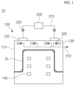
- Example embodiments of the present invention provide a drying system that includes an electrode drying equipment and a dehumidifier.
- the electrode drying system may further include a plurality of air supply fans each installed in one of the plurality of air supply pipes, and each of the plurality of air supply fans may be configured to provide a driving force for delivering the dry air through one of the plurality of air supply pipes.
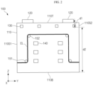
- the electrode drying equipment may further include a plurality of first rollers and a plurality of second rollers provided in the drying chamber and configured to support the electrode, and each of the plurality of first rollers maybe spaced apart from the top surface of the drying chamber with the plurality of second rollers interposed therebetween.
- the plurality of second rollers may be interposed between the plurality of first rollers in a direction in which the electrode extends.
- the plurality of first rollers and the plurality of second rollers may be configured to support the electrode such that a middle portion of the electrode is elevated compared to an edge portion of the electrode.
- the drying chamber may further include a bottom surface opposite to the top surface of the drying chamber, and a distance between each of the plurality of exhaust ports and the top surface of the drying chamber may be less than a distance between each of the plurality of exhaust ports and the bottom surface of the drying chamber.
- Each of the plurality of forced air supply devices may not overlap the electrode in a direction perpendicular to the top surface of the drying chamber.
- the electrode drying system may further include a plurality of passive air supply devices on a front surface of the drying chamber, and the front surface of the drying chamber may be opposite to the rear surface of the drying chamber.
- Example embodiments provide an electrode drying equipment.
- the electrode drying equipment includes a drying chamber, a plurality of forced air supply devices on a top surface of the drying chamber, and a plurality of exhaust ports on a rear surface of the drying chamber, in which each of the plurality of forced air supply devices is spaced apart from an electrode loaded in the drying chamber in a direction parallel to the top surface of the drying chamber.
- Each of the plurality of air supply devices may not overlap the electrode.
- the electrode drying equipment may further include a plurality of passive air supply devices configured to supply dry air to the drying chamber, and the plurality of passive air supply devices may be on the front surface of the drying chamber.
- a distance between each of the plurality of exhaust ports and the bottom surface of the drying chamber may be less than a distance between each of the plurality of exhaust ports and a top surface of the drying chamber, and the top surface of the drying chamber may be opposite to the bottom surface of the drying chamber.
- a moisture mass fraction in a drying chamber can be reduced, and the generation of vortexes and turbulence in the drying chamber can be alleviated. Accordingly, the uniformity and reliability of a drying process using a electrode drying system may improve. Effects achievable from example embodiments of the present invention are not limited to the above-described effects, and other effects that are not described herein will be clearly derived and understood by those of ordinary skilled in the art to which the example embodiments of the present invention pertain from the following description. That is, unintended effects achieved when the example embodiments of the present invention are implemented are derivable by those of ordinary skilled in the art from the example embodiments of the present invention.
- the drying process may include loading the electrode EL in the drying chamber 110 and then supplying dry air into the drying chamber 110.
- the drying process may be performed based on temperature control and dew point control inside the drying chamber 110.
- the drying process may include maintaining a temperature and a dew point in the drying chamber 110 to be within set ranges according to values measured by a temperature sensor and a dew point sensor installed inside the drying chamber 110.
- a dew point in the drying chamber 110 may be maintained to be about -70 °C or less but is not limited thereto.
- the dew point in the drying chamber 110 may be in a range of about -20 °C to about -70 °C.
- the dehumidifier 200 may be configured to generate dry air by removing pollutants and moisture from outside air.
- the dry air generated by the dehumidifier 200 may be distributed to each of parts and components of the electrode drying system 10 as needed.
- the electrode drying system 10 may include an environment control unit, and the environment control unit may control an atmosphere in the electrode drying system 10 using dry air generated by the dehumidifier 200.
- the dehumidifier 200 may be connected to a plurality of forced air supply devices 120 of the electrode drying equipment 100 through the plurality of air supply pipes 210.
- the plurality of forced air supply devices 120 may be connected directly to the dehumidifier 200 through the plurality of air supply pipes 210.
- Each of the plurality of air supply pipes 210 may be connected to the dehumidifier 200 and corresponding one among the plurality of forced air supply devices 120.
- connections between the plurality of air supply pipes 210 and the plurality of exhaust pipes 310 are indicated by dashed lines.
- the plurality of air supply fans 220 may be installed in the plurality of air supply pipes 210. Each of the plurality of air supply fans 220 may be configured to provide a driving force to move dry air through the plurality of air supply pipes 210. Each of the plurality of air supply fans 220 may be configured to adjust a flow rate of the dry air through the plurality of air supply pipes 210.
- Air inside the drying chamber 110 may be discharged through a plurality of exhaust ports 130. Humidity of the air inside the drying chamber 110 may be higher than that of dry air provided from the plurality of forced air supply devices 120 by performing the drying process.
- the plurality of exhaust ports 130 may discharge the air inside the drying chamber 110 such that an atmosphere (e.g., humidity, temperature, pressure, etc.) inside the drying chamber 110 may be kept constant.
- Each of the plurality of exhaust fans 320 may be installed on corresponding one of the plurality of exhaust pipes 310. Each of the plurality of exhaust fans 320 may provide a driving force to exhaust air from the drying chamber 110 through the plurality of exhaust pipes 310. Each of the plurality of exhaust fans 320 may adjust a flow rate of air discharged from the plurality of exhaust ports 130.
- the plurality of passive air supply devices 140 may each have a structure that may be opened and closed. When the plurality of passive air supply devices 140 are closed, the flow of air through the plurality of passive air supply devices 140 may be blocked and thus the plurality of passive air supply devices 140 may not provide dry air to the drying chamber 110. When the plurality of passive air supply devices 140 are open, the flow of air through the plurality of passive air supply devices 140 may be permitted and thus the plurality of passive air supply devices 140 may provide dry air to the drying chamber 110.
- the bottom surface 110B may face a bottom of a space in which the drying chamber 110 is installed.
- the top surface 110T may be opposite to the bottom surface 110B.
- the top surface 110T may be spaced apart from the bottom of the space, in which the drying chamber 110 is installed, with the bottom surface 110B interposed therebetween.
- the plurality of forced air supply devices 120 may be installed on the top surface 110T.
- Each of the first and second side surfaces 110S1 and 110S2 may be connected to the bottom surface 110B, the top surface 110T, the front surface 110F, and the rear surface 110R. Accordingly, the first and second side surfaces 110S1 and 110S2, the bottom surface 110B, the top surface 110T, the front surface 110F, and the rear surface 110R may form a closed space for the drying process.
- the plurality of second rollers 152 may be interposed between the plurality of first rollers 151 in the Y-axis direction. Accordingly, a middle portion of the electrode EL in the drying chamber 110 may be elevated compared to an edge portion of the electrode EL.
- the middle portion of the electrode EL is a portion of the electrode EL between the plurality of second rollers 152
- the edge portion of the electrode EL is a portion of the electrode EL between the plurality of first rollers 151 and the first and second side surfaces 110S1 and 110S2.
- the forced air supply devices 120 may be interposed between the surfaces of the first and second rollers 151 and 152 that support the electrodes EL and the front surface 110F in the X-axis direction. Accordingly, dry air introduced through the forced air supply devices 120 may be prevented from being directly sprayed to a certain portion of the electrode EL, and uniformity of the drying process may be improved.
- the forced air supply devices 120 was close to the top surface 110T of the drying chamber 110 and thus vortexes and turbulences decrease in the drying chamber 110. Furthermore, according to the experimental example, it was confirmed that an amount of water evaporation in the drying chamber 110 increased by about 30% compared to that in a conventional electrode drying equipment due to the provision of the above-described forced air supply devices 120. Accordingly, it was confirmed that the electrode drying equipment 100 and the electrode drying system 10 (see FIG. 1 ) including the same according to example embodiments contributed to improved uniformity and efficiency of the drying process.
- FIG. 4 is a diagram for describing an electrode drying equipment 101 according to other example embodiments. More specifically, FIG. 4 illustrates a part of the electrode drying equipment 101 corresponding to FIG. 2 .
- FIG. 5 is a diagram for describing an electrode drying equipment 102 according to other example embodiments. More specifically, FIG. 5 illustrates a part of the electrode drying equipment 102 corresponding to FIG. 2 .
- the electrode drying equipment 102 may include a drying chamber 110, a plurality of forced air supply devices 120 and 121, a plurality of exhaust ports 130 and 131, a plurality of passive air supply devices 140, a plurality of first rollers 151 and a plurality of second rollers 152.
- the drying chamber 110 and the plurality of passive air supply devices 140 are substantially the same as those described above with reference to FIG. 1 and thus a redundant description thereof is omitted here.
- the forced air supply devices 120 may be installed on a top surface 110T, and the forced air supply devices 121 may be installed on a bottom surface 110B.
- FIG. 5 illustrates that two forced air supply devices 120 are installed on the top surface 110T and one forced air supply device 121 is installed on the bottom surface 110B, and the number and arrangement of forced air supply devices 120 and the number of arrangement of forced air supply devices 121 may be changed as necessary.
- At least two second rollers 152 may be interposed between two neighboring ones of the first rollers 151, and at least two first rollers 151 may be interposed between two neighboring ones of the second rollers 152.
- a pass line of an electrode EL may have a zigzag shape unlike in the embodiments of FIGS. 2 and 4 .
- the electrode EL may be moved by rotation of the first and second rollers 151 and 152, and the pass line may be a moving path of the electrode EL.
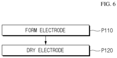
- FIG. 6 is a flowchart of a method of manufacturing an electrode according to example embodiments.
Landscapes
- Engineering & Computer Science (AREA)
- Mechanical Engineering (AREA)
- General Engineering & Computer Science (AREA)
- Textile Engineering (AREA)
- Life Sciences & Earth Sciences (AREA)
- Microbiology (AREA)
- Manufacturing & Machinery (AREA)
- Chemical & Material Sciences (AREA)
- Chemical Kinetics & Catalysis (AREA)
- Electrochemistry (AREA)
- General Chemical & Material Sciences (AREA)
- Battery Electrode And Active Subsutance (AREA)
- Drying Of Solid Materials (AREA)
Applications Claiming Priority (3)
| Application Number | Priority Date | Filing Date | Title |
|---|---|---|---|
| KR20230003506 | 2023-01-10 | ||
| KR1020240000998A KR20240111708A (ko) | 2023-01-10 | 2024-01-03 | 전극 건조 설비 및 이를 포함하는 전극 건조 시스템 |
| PCT/KR2024/000347 WO2024151027A1 (ko) | 2023-01-10 | 2024-01-08 | 전극 건조 설비 및 이를 포함하는 전극 건조 시스템 |
Publications (2)
| Publication Number | Publication Date |
|---|---|
| EP4582758A1 true EP4582758A1 (de) | 2025-07-09 |
| EP4582758A4 EP4582758A4 (de) | 2026-04-08 |
Family
ID=91897127
Family Applications (1)
| Application Number | Title | Priority Date | Filing Date |
|---|---|---|---|
| EP24741648.0A Pending EP4582758A4 (de) | 2023-01-10 | 2024-01-08 | Elektrodentrocknungsvorrichtung und elektrodentrocknungssystem damit |
Country Status (4)
| Country | Link |
|---|---|
| EP (1) | EP4582758A4 (de) |
| JP (1) | JP2025530533A (de) |
| CN (1) | CN119998610A (de) |
| WO (1) | WO2024151027A1 (de) |
Family Cites Families (22)
| Publication number | Priority date | Publication date | Assignee | Title |
|---|---|---|---|---|
| DE3026885A1 (de) * | 1980-07-16 | 1982-02-04 | Hostert Fotomata, 4006 Erkrath | Trockenschrank fuer aufsichtsmaterial o.dgl. |
| JP2003331849A (ja) * | 2002-05-09 | 2003-11-21 | Itochu Corp | 集電構造、電極構造及びそれらの製造方法 |
| JP5194745B2 (ja) * | 2007-11-29 | 2013-05-08 | トヨタ自動車株式会社 | シート状基材の乾燥装置 |
| JP4691175B2 (ja) * | 2009-04-28 | 2011-06-01 | 三菱重工業株式会社 | 乾燥装置 |
| JP5421934B2 (ja) * | 2011-01-13 | 2014-02-19 | 東京エレクトロン株式会社 | 電極製造装置、電極製造方法 |
| JP5788241B2 (ja) * | 2011-06-24 | 2015-09-30 | 株式会社ヒラノテクシード | 熱処理装置 |
| JP5691985B2 (ja) * | 2011-10-06 | 2015-04-01 | トヨタ自動車株式会社 | 電池用電極の製造方法 |
| JP5776508B2 (ja) * | 2011-11-22 | 2015-09-09 | トヨタ自動車株式会社 | 電極シートの乾燥装置 |
| JP5988358B2 (ja) * | 2012-07-02 | 2016-09-07 | Necエナジーデバイス株式会社 | リチウム二次電池に用いる塗布膜の乾燥方法 |
| US10276857B2 (en) * | 2012-09-25 | 2019-04-30 | Toyota Jidosha Kabushiki Kaisha | Method of manufacturing electrode for secondary battery and hot-gas drying furnace |
| CN203731822U (zh) * | 2013-12-24 | 2014-07-23 | 湖南兴瑞新材料研究发展有限公司 | 锂电池正极材料干燥用微波干燥机 |
| JP6417810B2 (ja) * | 2014-09-17 | 2018-11-07 | 株式会社豊田自動織機 | 乾燥装置及び電極の製造方法 |
| JP6149850B2 (ja) * | 2014-12-08 | 2017-06-21 | トヨタ自動車株式会社 | 膜電極接合体の製造方法 |
| JP2016188733A (ja) * | 2015-03-30 | 2016-11-04 | 株式会社Screenホールディングス | 乾燥装置および塗膜形成システム |
| CN206163605U (zh) * | 2016-11-07 | 2017-05-10 | 宁德时代新能源科技股份有限公司 | 极片冷压干燥装置 |
| KR102306546B1 (ko) * | 2018-05-23 | 2021-09-30 | 주식회사 엘지에너지솔루션 | 이차전지용 노칭장치 및 노칭방법 |
| CN209953198U (zh) * | 2018-11-13 | 2020-01-17 | 耿晋 | 一种进气装置及干燥单元 |
| CN110416001B (zh) * | 2019-01-14 | 2021-03-26 | 四川曦鸿电子科技有限公司 | 一种大型电容器批量自动干燥装置 |
| TWI893104B (zh) | 2020-04-21 | 2025-08-11 | 中國大陸商上海顯耀顯示科技有限公司 | 具反射元件之發光二極體晶片結構 |
| CN112815684B (zh) * | 2021-02-02 | 2022-12-09 | 江西春兴新能源有限公司 | 一种蓄电池固化后极板的连续微波干燥工艺方法 |
| CN216880227U (zh) * | 2021-12-16 | 2022-07-05 | 江苏乐士源新能源科技有限公司 | 一种涂布机 |
| KR20240000998A (ko) | 2022-06-24 | 2024-01-03 | (주)쁘띠엘린 | 영유아용 두상변형 방지 베개 |
-
2024
- 2024-01-08 CN CN202480004244.9A patent/CN119998610A/zh active Pending
- 2024-01-08 JP JP2025517806A patent/JP2025530533A/ja active Pending
- 2024-01-08 EP EP24741648.0A patent/EP4582758A4/de active Pending
- 2024-01-08 WO PCT/KR2024/000347 patent/WO2024151027A1/ko not_active Ceased
Also Published As
| Publication number | Publication date |
|---|---|
| JP2025530533A (ja) | 2025-09-11 |
| EP4582758A4 (de) | 2026-04-08 |
| CN119998610A (zh) | 2025-05-13 |
| WO2024151027A1 (ko) | 2024-07-18 |
Similar Documents
| Publication | Publication Date | Title |
|---|---|---|
| KR102824105B1 (ko) | 이차전지 | |
| US10056611B2 (en) | Method for testing cycle life of positive electrode active material for secondary battery | |
| KR20200029961A (ko) | 리튬 이차전지용 양극 활물질 및 이를 포함하는 리튬 이차전지 | |
| EP3863084B1 (de) | Negative elektrode und sekundärbatterie damit | |
| US20150086866A1 (en) | Flow controller of drying oven with automatic air charge for manufacturing secondary battery | |
| CN114930178B (zh) | 用于测量电池单体的容量的设备和方法 | |
| JP7771378B2 (ja) | 負極およびそれを含む二次電池 | |
| KR102567400B1 (ko) | 이차전지 | |
| KR20240020700A (ko) | 이차전지용 전극 제조방법, 이차전지용 전극 및 이를포함하는 이차전지 | |
| KR20240013696A (ko) | 고체 전해질, 이의 제조방법 및 이를 포함하는 전고체전지 | |
| CN111684627A (zh) | 锂二次电池用负极活性材料和包含其的锂二次电池用负极 | |
| KR101562571B1 (ko) | 전극 코팅량 자동 조절 장치 | |
| KR102621785B1 (ko) | Si 음극을 포함하는 리튬 이차전지 | |
| JP7507849B2 (ja) | 電池システム、その使用方法、およびそれを含む電池パック | |
| KR20190107648A (ko) | 전극조립체를 구성하는 분리막의 기공 내에 겔화 전해액 성분을 포함하고 있는 전지셀 | |
| KR20220009095A (ko) | 건조 장치 및 이를 포함하는 전극 제조 장치 | |
| KR20210104605A (ko) | 음극의 전리튬 방법, 전리튬화 음극, 및 이를 포함하는 리튬 이차전지 | |
| KR20240111708A (ko) | 전극 건조 설비 및 이를 포함하는 전극 건조 시스템 | |
| EP4582758A1 (de) | Elektrodentrocknungsvorrichtung und elektrodentrocknungssystem damit | |
| KR102852650B1 (ko) | 음극 및 이를 포함하는 이차전지 | |
| KR102900626B1 (ko) | 코팅 가이드를 포함하는 전극 제조 장치 | |
| KR20220109699A (ko) | 이차전지의 제조방법 | |
| EP4468381A1 (de) | Elektrodentrocknungssystem und elektrodentrocknungsverfahren damit | |
| KR20210146521A (ko) | 리튬 이차전지의 퇴화 원인 진단 방법 | |
| KR102071868B1 (ko) | 에어 블로잉 유닛을 포함하는 전극조립체 제조 장치 |
Legal Events
| Date | Code | Title | Description |
|---|---|---|---|
| STAA | Information on the status of an ep patent application or granted ep patent |
Free format text: STATUS: THE INTERNATIONAL PUBLICATION HAS BEEN MADE |
|
| PUAI | Public reference made under article 153(3) epc to a published international application that has entered the european phase |
Free format text: ORIGINAL CODE: 0009012 |
|
| STAA | Information on the status of an ep patent application or granted ep patent |
Free format text: STATUS: REQUEST FOR EXAMINATION WAS MADE |
|
| 17P | Request for examination filed |
Effective date: 20250401 |
|
| AK | Designated contracting states |
Kind code of ref document: A1 Designated state(s): AL AT BE BG CH CY CZ DE DK EE ES FI FR GB GR HR HU IE IS IT LI LT LU LV MC ME MK MT NL NO PL PT RO RS SE SI SK SM TR |
|
| A4 | Supplementary search report drawn up and despatched |
Effective date: 20260306 |
|
| RIC1 | Information provided on ipc code assigned before grant |
Ipc: F26B 21/00 20060101AFI20260302BHEP Ipc: H01M 4/04 20060101ALI20260302BHEP Ipc: F26B 21/33 20260101ALI20260302BHEP Ipc: F26B 13/14 20060101ALI20260302BHEP Ipc: F26B 25/06 20060101ALI20260302BHEP Ipc: F26B 3/04 20060101ALI20260302BHEP Ipc: F26B 13/08 20060101ALI20260302BHEP |
|
| DAV | Request for validation of the european patent (deleted) | ||
| DAX | Request for extension of the european patent (deleted) |