JP2004012811A - Optical fiber ribbon with jacket - Google Patents
Optical fiber ribbon with jacket Download PDFInfo
- Publication number
- JP2004012811A JP2004012811A JP2002166174A JP2002166174A JP2004012811A JP 2004012811 A JP2004012811 A JP 2004012811A JP 2002166174 A JP2002166174 A JP 2002166174A JP 2002166174 A JP2002166174 A JP 2002166174A JP 2004012811 A JP2004012811 A JP 2004012811A
- Authority
- JP
- Japan
- Prior art keywords
- optical fiber
- jacket
- fiber ribbon
- coated optical
- flame
- Prior art date
- Legal status (The legal status is an assumption and is not a legal conclusion. Google has not performed a legal analysis and makes no representation as to the accuracy of the status listed.)
- Pending
Links
Images

Abstract
Description
【0001】
【発明の属する技術分野】
本発明は、光接続箱等に配線される光ファイバテープ心線に関する。
【0002】
【従来の技術】
近年は、情報量の増大、光通信の利用の加速化に伴い、光ファイバが通信局間の長距離通信に加えて、局内、構内のシステム配線も多心化が要求されるようになってきている。そして、一般家庭へ布設される状況となり、伝送距離の短い光ファイバシステムでは、接続技術や接続作業が重要な事項となっている。
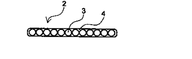
図3は、従来の光ファイバテープ心線の断面図である。図3において、3は光ファイバ素線であり、コアとクラッドからなる光ファイバに紫外線硬化樹脂等の一次被覆あるいはさらに二次被覆されたものである。光ファイバテープ心線2は、この光ファイバ素線3を一平面状に配列し、それの外周に一括して紫外線硬化樹脂等からなる共通被覆4(この被覆は内部層と外部層の二層からなる場合もある)を被せたものであり、高密度実装が可能であるため、多心のケーブルに適しており多用されている。
また、光ファイバテープ心線として、側圧特性を向上させる等のため、上記した一括被覆した後に更にその外側を紫外線硬化型樹脂等で被覆した外被付き光ファイバテープ心線も知られている。
そして、伝送距離の短い光接続箱内部や伝送装置内等の配線においても、このような外被のない光ファイバテープ心線をそのまま配線させる方法を採用しているのが一般的である。この光ファイバテープ心線をそのまま配線させる方法では、配線作業中に、接続箱内の突出部やバリ等の鋭利な部位にテープ心線を引っかけたり、光ファイバテープ心線に強度な衝撃を与えたりして、光ファイバテープ心線を損傷させてしまう場合が多々あり、配線作業に時間と熟練を要した。また、外被付きのものを配線するには、光ファイバテープ心線の端末部の外被層を剥ぎ取る作業が必要である。
【0003】
【発明が解決しようとする課題】
配線作業に当たって、このような外被を持つ光ファイバテープ心線の端末部での被覆の剥ぎ取りには大きな力を要し、その力は1500gf/200mm以上であり、外被と光ファイバテープ心線のグリップ力が高いためにテープ心線状態として取り出すことができにくいため、外被を被せないテープ心線をそのまま使用していた。
また、光ファイバテープ心線の被覆には、一般的に紫外線硬化型樹脂を使用しているが、紫外線硬化型樹脂は非常に燃えやすい材料であるため、万一、火災が発生して、光ファイバテープ心線に着火した場合、光ファイバテープ心線が導火線のような役割を担い、火災を拡大させてしまうといった危険性もある。
そこで、本発明は、光ファイバテープ心線を保護し、端末部加工時にファイバを損傷することなく小さな力で被覆除去が容易にでき、さらに、光ファイバテープ心線のみよりも難燃特性を向上させ、低温時にも光損失値が増加しない外被付き光ファイバテープ心線を提供することを目的とする。
【0004】
【課題を解決するための手段】
本発明者等は、上記課題に鑑み光ファイバ心線の構造について検討した結果、特定の剥ぎ取り力をもつ外被を有するものが良いとの知見を得た。そこでこれらの知見に基づいて本発明をなすに至った。
すなわち、本発明は、
(1)予め作成しておいたチューブ状被覆に光ファイバテープ心線を通すか、もしくは光ファイバテープ心線の外周に押出し成形することにより、光ファイバテープ心線の外周に難燃性プラスチック外被が形成され、その外被剥ぎ取り力が100gf/200mm以上1000gf/200mm以下であることを特徴とする外被付き光ファイバテープ心線、
(2)前記難燃性プラスチック外被は、その酸素指数が25以上であることを特徴とする(1)に記載の外被付き光ファイバテープ心線、
(3)前記難燃性プラスチック外被の厚さは、0.2mm以上であることを特徴とする(1)又は(2)に記載の外被付き光ファイバテープ心線、及び、
(4)前記難燃性プラスチック外被の厚さは、0.8mm以下であることを特徴とする(1)、(2)又は(3)に記載の外被付き光ファイバテープ心線、
を提供するものである。
【0005】
【発明の実施の形態】
次に、本発明の外被付き光ファイバテープ心線について図面を参照してさらに詳細に説明する。
図1は本発明の一実施態様である外被付き光ファイバテープ心線の構造を示す断面図であり、符号は重複を避けるため従来例と同一なものは同符号とする。
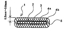
この実施態様では、12心の外被付き光ファイバテープ心線を示しているが、光ファイバ素線の数は12本に限らず、複数本であれば必要に応じ適宜設定できる。12本の光ファイバ素線3,3・・・・を一平面状に平行に配置し、それらを紫外線硬化型樹脂で二層(内部層4aと外部層4b)に被覆して光ファイバテープ心線2を形成している。勿論、紫外線硬化型樹脂の共通被覆4は、一層であってもよい。そして、さらにその外周に外被5を被せ、外被付き光ファイバテープ心線1を形成している。
【0006】
本発明のこのような外周の外被5は、従来周知の被覆手段である光ファイバテープ心線をダイス部へ通し、被覆樹脂をダイス部へ加圧押出しする方法では、下層と外被5との密着力をコントロールすることが難しいことから、外被の剥ぎ取り力を小さくすることは困難である。そこで、本発明では、パイプ押出し成形手段にて両者の密着力をコントロールすることによって所望の外被剥ぎ取り力をもつ外被5を被せることができる。
本発明のパイプ押出し法は、光ファイバテープ心線に被せる樹脂の「締め付け力」「グリップ力」をニップルやダイスの設定を変えることにより、外被5の剥ぎ取り力を100gf/200mm〜1000gf/200mmにすることができる。
【0007】
また、本発明の外被5の被覆手段としては、予め作成しておいたチューブ状被覆に光ファイバテープ心線2を挿入する方法が好ましい。この方法は、熱を加えることにより収縮するチューブを選定し、光ファイバテープ心線の外径より大きい内径のチューブに光ファイバテープ心線2を通し、その後熱を加えることによりチューブを収縮させて加工した製品である。光ファイバテープ心線の外径とチューブ内径との差、加熱速度及び加熱温度により密着力をコントロールすることができる。
例えば、テープ心線の長辺外径とチューブ内径との差を0.2〜0.4mm、熱収縮率50%程度、所定の肉厚のチューブを用いて、90〜120℃に2〜4分保持することにより、外被5の剥ぎ取り力を100gf/200mm〜1000gf/200mmにすることができる。
【0008】
このコントロールにより光ファイバテープ心線に被覆している外被の剥ぎ取り力が100gf/200mm以上1000gf/200mm以下にされる。剥ぎ取り力が100gf/200mm未満ではハンドリング時に外被のみがずれてしまい端末部にてテープ心線が露出するため100gf/200mm以上の剥ぎ取り力が必要である。また、その値が大き過ぎると、先にも述べたようにテープ心線状態で取り出すことができにくく、心線端末の作業性が極めて悪くなる。好ましくは300gf/200mm〜800gf/200mm、更に好ましくは500gf/200mm〜700gf/200mmである。
このように外被の剥ぎ取り力が従来のものに比べ低く、適度の範囲にあるので、カッターなどの一般的な工具を使用することにより、容易に難燃プラスチック外被のみを剥ぎ取ることができ、ファイバの光損失増を招くことがない。
【0009】
上記に示した外被剥ぎ取り力は、以下のようにして測定したものである。図2に示すように、350mm長の外被付きテープ心線1の両端部の外被を剃り刃等の鋭利な刃物にて一方端(左)を50mm、他方端(右)を100mmそれぞれ剥ぎ取り、その中間部に250mmの外被5を残す。その後、残った外被部を固定し、100mm剥ぎ取った心線部を引っ張り試験機6に固定し、外被部からテープ心線部を引き抜くのに要する力を測定し、その値を外被剥ぎ取り力とした。
【0010】
本発明の難燃性プラスチック外被材料は、テープ心線の共通被覆材が紫外線硬化型材料であることから、紫外線硬化型材料で被覆を施しても密着してしまうことは明らかであることから、難燃性プラスチック外被材料としては、ポリ塩化ビニル樹脂、難燃性ポリオレフィン樹脂が好ましく、これに限定されるものではなくポリアミド樹脂等も使用できる。
このような難燃性プラスチック外被材料は、上記したものに難燃性を付与させて使用することもできる。被覆を難燃化する方法としては、樹脂を合成する時に難燃性を付与することもでき、また、難燃性を付与されていない材料にも後から、例えば硬化前に難燃剤の添加を行うこともできる。
難燃剤としては、例えば、含ハロゲンリン酸エステル系、非ハロゲンリン酸エステル系、あるいは反応型ハロゲン系難燃剤等公知のものが利用できる。
外被の材料は、難燃性を考慮して、酸素指数25以上、好ましくは酸素指数27以上である難燃性プラスチック材料を使用するが、難燃剤の配合量を多くし過ぎると被覆層の物性が低下するので、酸素指数は40程度が上限となる。ここで示す酸素指数は、JIS K7201『酸素指数法による高分子材料の燃焼試験方法』により求められたものである。
【0011】
酸素指数25の難燃性プラスチック材料を使用した外被付き光ファイバテープ心線で、光ファイバケーブルの一般的な燃焼試験であるUL1581VW−1燃焼試験を行った実験の結果によると、外被厚さが0.2mm以上あれば、十分な難燃特性が得られることがわかった。勿論、酸素指数がより高い材料を使用すれば、外被の厚さはさらに薄くすることができることは容易に推測される。
また、この外被とする難燃性プラスチック材料は、低温時に収縮することが知られている。被覆材料の収縮量が大きいと、光ファイバテープ心線に曲げ応力を与えてしまい、光ファイバテープ心線の光損失値を増加させてしまう恐れがあるのはよく知られたことである。その収縮量は、一般に被覆の断面積に比例しているため、外被の厚さは、薄いほど良いことになる。光ファイバの心線数、プラスチック材料の線膨張係数にもよるが、厚さ0.8mm以下であれば、光ファイバテープ心線を曲げてしまうことはない。
【0012】
【実施例】
次に、本発明を実施例により更に具体的に示すが、本発明はこの実施例に限定されるものではない。
紫外線硬化型樹脂からなる被覆を施された径250μmの光ファイバ素線3が8本、図1に示すように平面状に平行に配列され、ウレタンアクリレート系の紫外線硬化型樹脂で一括被覆され、外径:0.4mm×2.1mmの8心テープ心線2が得られた。
チューブ寸法が、内径2.4mm、外径2.7mmで、酸素指数35の電子線架橋軟質難燃性ポリオレフィン製のチューブ内に前記8心テープ心線を挿入し、100℃に3分保持して、外被付き光ファイバテープ心線を得た。得られた外被付き光ファイバテープ心線の外被剥ぎ取り力は、平均値で500gf/200mmであった。
【0013】
【発明の効果】
本発明の外被付き光ファイバテープ心線を使用した場合、一般的な工具を使用して簡単に外被を剥ぎ取ることができ、光ファイバテープ心線端末にコネクター等を取り付けることができる。光配線箱等の配線に本発明の外被付き光ファイバテープ心線を使用した場合、従来の光ファイバテープ心線を配線させる作業と比較して、外傷からの保護のために光ファイバテープ心線の外周に被覆を施しているため、光ファイバの取り扱い性が容易になる。
また、外被の材料に難燃プラスチックを使用しているため、難燃特性も向上させることができると共に、低温時でも光ファイバの光損失増を防止できる。
【図面の簡単な説明】
【図1】本発明の外被付き光ファイバテープ心線の一例を示す断面図である。
【図2】剥ぎ取り力の測定方法を示す簡略説明図で、(a)はテープ心線の長手方向に対し垂直な断面図、(b)は正面図である。
【図3】従来の光ファイバテープ心線の断面図である。
【符号の説明】
1 外被付き光ファイバテープ心線
2 光ファイバテープ心線
3 光ファイバ素線
4 共通被覆
5 外被
6 引っ張り試験機[0001]
TECHNICAL FIELD OF THE INVENTION
The present invention relates to an optical fiber tape cored in an optical connection box or the like.
[0002]
[Prior art]
In recent years, as the amount of information has increased and the use of optical communication has been accelerated, it has become necessary to use optical fibers in addition to long-distance communication between communication stations, as well as to increase the number of cores used in system wiring within offices and premises. ing. Then, the optical fiber system is laid in a general home. In an optical fiber system having a short transmission distance, connection technology and connection work are important matters.
FIG. 3 is a cross-sectional view of a conventional optical fiber ribbon. In FIG. 3, reference numeral 3 denotes an optical fiber, which is obtained by coating an optical fiber comprising a core and a clad with a primary coating such as an ultraviolet curable resin or further with a secondary coating. The
Further, as an optical fiber ribbon, there is also known an optical fiber ribbon with a jacket in which the outside is further covered with an ultraviolet curable resin or the like after the above-mentioned batch coating in order to improve the lateral pressure characteristics and the like.
In general, a method in which an optical fiber ribbon without such a jacket is directly wired even in an optical connection box or a transmission device having a short transmission distance is used. In the method of wiring the optical fiber ribbon as it is, during the wiring work, the tape ribbon is hooked on a sharp part such as a protrusion or a burr in the connection box, or a strong impact is given to the optical fiber ribbon. In many cases, the optical fiber ribbon is damaged, and the wiring work requires time and skill. In addition, in order to wire a cable with a jacket, it is necessary to strip the jacket layer at the end of the optical fiber ribbon.
[0003]
[Problems to be solved by the invention]
In the wiring work, a large force is required to peel off the coating at the end of the optical fiber ribbon having such a jacket, and the force is 1500 gf / 200 mm or more. Since the wire has a high grip force, it is difficult to take it out in a tape core state, so that the tape core without covering is used as it is.
In addition, UV-curable resin is generally used for coating the optical fiber ribbon, but since UV-curable resin is a very flammable material, a fire may occur and When the fiber ribbon is ignited, there is a danger that the optical fiber ribbon plays a role as a squib and the fire is spread.
Therefore, the present invention protects the optical fiber ribbon, easily removes the coating with a small force without damaging the fiber when processing the end portion, and further improves the flame retardancy characteristics compared to the optical fiber ribbon alone. It is another object of the present invention to provide a sheathed optical fiber tape in which the optical loss value does not increase even at a low temperature.
[0004]
[Means for Solving the Problems]
The present inventors have studied the structure of an optical fiber core wire in view of the above problem, and as a result, have found that it is better to have a jacket having a specific peeling force. Therefore, the present invention has been made based on these findings.
That is, the present invention
(1) An optical fiber tape core wire is passed through a previously formed tubular coating or extruded around the optical fiber tape core wire to form an outer periphery of the optical fiber tape core with a flame-retardant plastic. An optical fiber tape with a jacket, wherein the jacket is formed and the sheath peeling force is 100 gf / 200 mm or more and 1000 gf / 200 mm or less;
(2) The optical fiber tape with a jacket according to (1), wherein the flame retardant plastic jacket has an oxygen index of 25 or more.
(3) The thickness of the flame-retardant plastic jacket is 0.2 mm or more, and the optical fiber ribbon with the jacket according to (1) or (2), and
(4) The optical fiber tape with the jacket according to (1), (2) or (3), wherein the thickness of the flame-retardant plastic jacket is 0.8 mm or less.
Is provided.
[0005]
BEST MODE FOR CARRYING OUT THE INVENTION
Next, the optical fiber ribbon with a jacket according to the present invention will be described in more detail with reference to the drawings.
FIG. 1 is a cross-sectional view showing the structure of an optical fiber ribbon with a jacket according to one embodiment of the present invention.
In this embodiment, a twelve-core optical fiber tape with a sheath is shown, but the number of optical fiber strands is not limited to twelve, and any number of optical fiber strands can be appropriately set as needed. Are arranged in parallel in one plane, and they are coated in two layers (an inner layer 4a and an outer layer 4b) with an ultraviolet-curable resin to form an optical fiber tape core.
[0006]
In the method of the present invention, in which the
In the pipe extrusion method of the present invention, the "tightening force" and "grip force" of the resin applied to the optical fiber ribbon are changed by changing the setting of the nipple and the die, so that the peeling force of the
[0007]
As a means for coating the
For example, the difference between the outer diameter of the long side of the tape core wire and the inner diameter of the tube is 0.2 to 0.4 mm, the heat shrinkage is about 50%, and a tube having a predetermined thickness is used. By holding for a minute, the peeling force of the
[0008]
By this control, the peeling force of the jacket covering the optical fiber ribbon is set to 100 gf / 200 mm or more and 1000 gf / 200 mm or less. If the peeling force is less than 100 gf / 200 mm, only the jacket is displaced during handling, and the tape core is exposed at the terminal portion, so that a peeling force of 100 gf / 200 mm or more is required. On the other hand, if the value is too large, it is difficult to take out the tape in the state of the cord as described above, and the workability of the cord terminal becomes extremely poor. Preferably it is 300 gf / 200 mm to 800 gf / 200 mm, more preferably 500 gf / 200 mm to 700 gf / 200 mm.
As described above, the peeling force of the outer cover is lower than that of the conventional one and is in an appropriate range. Therefore, by using a general tool such as a cutter, it is possible to easily peel off only the flame-retardant plastic outer cover. It does not cause an increase in optical loss of the fiber.
[0009]
The sheath peeling force shown above was measured as follows. As shown in FIG. 2, the outer and outer ends of the tape core wire 1 having a length of 350 mm are shaved, and one end (left) is peeled off by 50 mm and the other end (right) is peeled off by 100 mm with a sharp blade such as a blade. And leave a 250
[0010]
In the flame-retardant plastic sheath material of the present invention, since the common coating material of the tape core wire is an ultraviolet-curing material, it is clear that even if the coating is performed with the ultraviolet-curing material, it will be in close contact. The flame-retardant plastic material is preferably a polyvinyl chloride resin or a flame-retardant polyolefin resin, but is not limited thereto, and a polyamide resin or the like can be used.
Such a flame-retardant plastic jacket material can be used by imparting flame retardancy to the above-mentioned ones. As a method of making the coating flame-retardant, flame retardancy can also be imparted when synthesizing the resin.Addition of a flame retardant before curing, for example, also to a material that is not imparted with flame retardancy, is also possible. You can do it too.
As the flame retardant, for example, known ones such as a halogen-containing phosphoric ester, a non-halogen phosphoric ester, or a reactive halogen-based flame retardant can be used.
As the material of the jacket, a flame-retardant plastic material having an oxygen index of 25 or more, preferably 27 or more, is used in consideration of the flame retardancy. Since the physical properties deteriorate, the upper limit of the oxygen index is about 40. The oxygen index shown here was determined according to JIS K7201 “Method for Combustion Test of Polymer Material by Oxygen Index Method”.
[0011]
According to the result of an experiment in which a UL1581VW-1 burning test, which is a general burning test of an optical fiber cable, was performed using a sheathed optical fiber tape using a flame-retardant plastic material having an oxygen index of 25, It was found that sufficient flame-retardant properties were obtained when the thickness was 0.2 mm or more. Of course, it is easily presumed that the thickness of the jacket can be further reduced by using a material having a higher oxygen index.
It is also known that the flame-retardant plastic material used as the jacket shrinks at low temperatures. It is well known that a large amount of shrinkage of the coating material causes a bending stress to be applied to the optical fiber ribbon, which may increase the optical loss value of the optical fiber ribbon. Since the amount of shrinkage is generally proportional to the cross-sectional area of the coating, the thinner the jacket, the better. Depending on the number of cores of the optical fiber and the coefficient of linear expansion of the plastic material, if the thickness is 0.8 mm or less, the optical fiber ribbon will not be bent.
[0012]
【Example】
Next, the present invention will be described more specifically with reference to examples, but the present invention is not limited to these examples.
Eight optical fiber strands 3 having a diameter of 250 μm coated with a UV-curable resin are arranged in parallel in a plane as shown in FIG. 1 and are collectively covered with a urethane acrylate UV-curable resin. An eight-
The 8-core tape is inserted into a tube made of an electron beam crosslinked soft flame-retardant polyolefin having an inner diameter of 2.4 mm and an outer diameter of 2.7 mm and an oxygen index of 35, and kept at 100 ° C. for 3 minutes. Thus, a sheathed optical fiber tape was obtained. The stripping force of the obtained coated optical fiber tape was 500 gf / 200 mm on average.
[0013]
【The invention's effect】
When the optical fiber ribbon with the sheath of the present invention is used, the sheath can be easily peeled off using a general tool, and a connector or the like can be attached to the end of the optical fiber ribbon. When using the sheathed optical fiber tape of the present invention for the wiring of an optical wiring box or the like, compared with the conventional work of wiring the optical fiber tape, the optical fiber tape for protection from external damage is provided. Since the outer periphery of the wire is covered, the handling of the optical fiber becomes easy.
Further, since the flame-retardant plastic is used as the material of the jacket, the flame-retardant properties can be improved and the optical loss of the optical fiber can be prevented from increasing even at a low temperature.
[Brief description of the drawings]
FIG. 1 is a cross-sectional view showing an example of an optical fiber tape cored cable according to the present invention.
FIGS. 2A and 2B are simplified explanatory views showing a method for measuring a peeling force, in which FIG.
FIG. 3 is a cross-sectional view of a conventional optical fiber ribbon.
[Explanation of symbols]
DESCRIPTION OF SYMBOLS 1 Optical fiber tape core with a
Claims (4)
Priority Applications (1)
| Application Number | Priority Date | Filing Date | Title |
|---|---|---|---|
| JP2002166174A JP2004012811A (en) | 2002-06-06 | 2002-06-06 | Optical fiber ribbon with jacket |
Applications Claiming Priority (1)
| Application Number | Priority Date | Filing Date | Title |
|---|---|---|---|
| JP2002166174A JP2004012811A (en) | 2002-06-06 | 2002-06-06 | Optical fiber ribbon with jacket |
Publications (1)
| Publication Number | Publication Date |
|---|---|
| JP2004012811A true JP2004012811A (en) | 2004-01-15 |
Family
ID=30433833
Family Applications (1)
| Application Number | Title | Priority Date | Filing Date |
|---|---|---|---|
| JP2002166174A Pending JP2004012811A (en) | 2002-06-06 | 2002-06-06 | Optical fiber ribbon with jacket |
Country Status (1)
| Country | Link |
|---|---|
| JP (1) | JP2004012811A (en) |
Cited By (3)
| Publication number | Priority date | Publication date | Assignee | Title |
|---|---|---|---|---|
| JP2009509202A (en) * | 2005-09-23 | 2009-03-05 | ネクストロム・オサケユキテュア | Coating line method and line configuration |
| JP2013178346A (en) * | 2012-02-28 | 2013-09-09 | Furukawa Electric Co Ltd:The | Optical fiber ribbon and method for manufacturing the same |
| US10368746B2 (en) | 2014-07-11 | 2019-08-06 | Cardiac Pacemakers, Inc. | Power saving communication for medical devices |
-
2002
- 2002-06-06 JP JP2002166174A patent/JP2004012811A/en active Pending
Cited By (4)
| Publication number | Priority date | Publication date | Assignee | Title |
|---|---|---|---|---|
| JP2009509202A (en) * | 2005-09-23 | 2009-03-05 | ネクストロム・オサケユキテュア | Coating line method and line configuration |
| JP4750852B2 (en) * | 2005-09-23 | 2011-08-17 | ネクストロム・オサケユキテュア | Coating line method and line configuration |
| JP2013178346A (en) * | 2012-02-28 | 2013-09-09 | Furukawa Electric Co Ltd:The | Optical fiber ribbon and method for manufacturing the same |
| US10368746B2 (en) | 2014-07-11 | 2019-08-06 | Cardiac Pacemakers, Inc. | Power saving communication for medical devices |
Similar Documents
| Publication | Publication Date | Title |
|---|---|---|
| CN100365458C (en) | Peelable cushioning layer with preferential tearing portion and method of making the same | |
| JP4049154B2 (en) | Optical fiber ribbon | |
| US20220026659A1 (en) | High fiber count pre-terminated optical distribution assembly | |
| US5627932A (en) | Reduced diameter indoor fiber optic cable | |
| US5201020A (en) | Reinforced protective tube for optical waveguide fibers | |
| JP4291767B2 (en) | Improved fiber optic cable | |
| EP1324091A2 (en) | Reinforced tight-buffered optical fiber and cables made with same | |
| US10025053B2 (en) | Optical fiber bundle | |
| JPWO2003098307A1 (en) | Tape-shaped optical fiber core, method for manufacturing the same, connector with tape core, optical fiber array with tape core, and optical wiring system | |
| JPH02289805A (en) | fiber optic unit | |
| US10031303B1 (en) | Methods for forming tight buffered optical fibers using compression to facilitate subsequent loosening | |
| US20160103288A1 (en) | Optical fiber cables with polypropylene binder | |
| JP2004012811A (en) | Optical fiber ribbon with jacket | |
| JP4205523B2 (en) | Drop optical fiber cable | |
| JP2004252388A (en) | Optical fiber | |
| JP4927700B2 (en) | Optical fiber cable and method for manufacturing the optical fiber cable | |
| CN109541765B (en) | Optical fiber and optical cable using same | |
| CN1989433A (en) | Optical cable and method for the production thereof | |
| JP3346254B2 (en) | Optical fiber | |
| JP4094630B2 (en) | Single fiber separation method of optical fiber tape | |
| JPH095587A (en) | Optical fiber strand | |
| JP2007065595A (en) | Fiber optic cable | |
| JP2006078913A (en) | Optical fiber tape and optical fiber cable | |
| JP2005221839A (en) | Optical fiber and optical fiber tape | |
| JP2005077703A (en) | Optical drop cable |
Legal Events
| Date | Code | Title | Description |
|---|---|---|---|
| A621 | Written request for application examination |
Free format text: JAPANESE INTERMEDIATE CODE: A621 Effective date: 20050201 |
|
| A977 | Report on retrieval |
Free format text: JAPANESE INTERMEDIATE CODE: A971007 Effective date: 20060601 |
|
| A131 | Notification of reasons for refusal |
Free format text: JAPANESE INTERMEDIATE CODE: A131 Effective date: 20060606 |
|
| A521 | Request for written amendment filed |
Free format text: JAPANESE INTERMEDIATE CODE: A523 Effective date: 20060807 |
|
| A131 | Notification of reasons for refusal |
Free format text: JAPANESE INTERMEDIATE CODE: A131 Effective date: 20070306 |
|
| A521 | Request for written amendment filed |
Free format text: JAPANESE INTERMEDIATE CODE: A523 Effective date: 20070427 |
|
| A02 | Decision of refusal |
Free format text: JAPANESE INTERMEDIATE CODE: A02 Effective date: 20070612 |