【0001】
【発明の属する技術分野】
この発明は、水や空気の噴射により緯入れする流体噴射式織機の筬清浄装置に関する。
【0002】
【従来の技術】
一般に、水や空気の噴射により緯入れする流体噴射式織機においては、緯糸の飛走路の汚れが織機稼働率や織物品質に大きな影響を与える。従って、通常は織機稼働の一定時間毎に、織機ユーザーまたは筬の製造者が織機の筬を洗浄している。筬の清浄は、織機を一旦止め、先ず経糸を緩めて筬の下方に下げ、筬羽に洗浄剤を噴射する。この後、人手で筬羽をブラッシングし、洗浄水を噴射して洗浄剤を流す。そして、乾燥用の空気を筬羽に噴射して、筬羽を乾かし、経糸を張り直し、織機を再稼働するというものである。
【0003】
また、特許第2911658号公報に開示されているように、サブノズルを備えた空気噴射式織機のサブノズルから清浄液が噴射され、空気ノズル及び筬の清浄を行うものも提案されている。
【0004】
【発明が解決しようとする課題】
上記従来の技術の前者の人手により洗浄する場合、清浄のための段取りや作業に多くの時間がかかり、織機稼働率の低下を招いているという問題があった。また。上記従来の技術の後者の特許公報に開示された技術の場合、サブノズルに洗浄液を通して噴射するので、緯糸飛走方向に洗浄液が飛び、筬羽に効果的に洗浄液が当たらず、筬羽の洗浄効果が低いものである。
【0005】
この発明は上記従来の問題点に鑑みてなされたものであり、簡単な構造で、確実に効率よく筬の清浄が可能な流体噴射式織機の筬清浄装置を提供することを目的とする。
【0006】
【課題を解決するための手段】
この発明は、織機の筬保持部分に設けられ、筬の長手方向に沿って所定間隔で形成され筬羽の緯糸飛走路近傍を向いた複数の噴射口と、この噴射口に連通し筬の長手方向に形成され筬羽の洗浄液や空気等の清浄流体が通過する清浄流体路とを設けた流体噴射式織機の筬清浄装置である。
【0007】
上記噴射口と清浄流体路は、筬羽の保持部材に形成され筬と一体に設けられたものである。または、上記噴射口と清浄流体路は、筬を保持する筬保持具に設けられたものでも良い。そして、上記清浄流体路は、切替弁を介して、水と洗浄液及び空気等を送る各清浄流体供給源に接続されている。
【0008】
【発明の実施の形態】
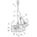
以下、この発明の実施形態について図面に基づいて説明する。図1は、この発明の第一実施形態を示すもので、この流体噴射式織機の筬清浄装置10は、多数の薄い筬羽12と、この筬羽12を保持した保持部材14から成る筬16に一体に設けられている。筬羽12は、互いに等間隔に位置し筬羽12の表裏の側面は経糸開口面に対して平行に設けられ、この実施形態の筬羽12には、緯糸Yが流体ジェットにより通過する緯糸案内部16aが形成されている。
【0009】
この実施形態の流体噴射式織機の筬清浄装置10は、織機に揺動自在に設けられ図示しない駆動機構により所定の揺動運動を行なう筬保持具20に取り付けられた筬16に設けられたもので、筬羽12の保持部材14に一体に設けられている。保持部材14には、筬16の長手方向に沿って所定間隔で形成され、筬羽12の緯糸案内部16aと緯糸飛走路近傍方向を向いた複数の噴射口22が形成されている。この噴射口22は、保持部材14内に長手方向に筬16の全幅に渡って形成され、筬羽12の洗浄液や空気等の清浄流体が通過する清浄流体路24に連通している。
【0010】
筬保持具20には、筬羽12の保持部材14を挟むように収容する断面コ字状の収容凹部30が形成され、保持部材14が押しつけられる側壁30aを備える。収容凹部30の他方の側壁30bは、わずかに上方に広がるように斜めに形成され、適宜の箇所に固定用ブロック32がクサビ状に嵌合されている。固定用ブロック32には、ボルト34の挿通孔が形成され、ボルト34は、収容凹部30の底面30cに形成された雌ネジ孔30dに螺合している。また、側壁30a側の外側面には、適宜の間隔で筬保持具20の長手方向に沿って補助ノズル18が取り付けられている。
【0011】
噴射口22と清浄流体路24には、切替弁36を介して、洗浄液供給源38、水供給源40,及び空気供給源42が接続されている。各供給源38,40,42には、各々供給ポンプが設けられている。なお、水供給源を水道に接続し、空気供給源を工場内の圧縮空気の配管と共用するとよい。
【0012】
次に、この実施形態の流体噴射式織機の筬清浄装置10の動作作用について説明する。まず、筬羽12が保持部材14に設けられた状態で、保持部材14を筬保持具20の収容凹部30に嵌合させる。そして、固定用ブロック32をクサビ状に嵌合させて、固定用ブロック32にボルト34を挿通し、ボルト34の雄ネジを収容凹部30の底面30cに形成された雌ネジ孔30dに螺合させる。固定用ブロック32は、筬16の長手方向に沿って適宜配置される。
【0013】
この後、筬16により製織動作が行なわれ、所定期間後に筬16の洗浄が必要となると、先ず、経糸をゆるめて筬16の上方に上げるか、または下方に下げる。そして筬16に向かって洗浄液供給源38から洗浄剤の入った洗浄液を洗浄流体路24に送り、噴射口22から洗浄液を筬羽12に吹き付ける。この後適宜ブラッシングし、筬羽12の汚れを落とす。
【0014】
そして、切替弁36を切り替えて、水供給源40から洗浄水を洗浄流体路24に送り噴射口22から洗浄水を筬羽12に吹き付け、洗浄剤とともに汚れを洗い流す。次に、切替弁36を切り替えて、空気供給源42から空気を洗浄流体路24に送り噴射口22から空気を筬羽12に吹き付け、乾燥させる。この後、経糸を張り直し、織機を再稼働する。
【0015】
なお、洗浄剤、洗浄水、空気の何れかを混合して吹き付けても良い。また切替弁36を図示しない制御装置と接続し、自動的に洗浄剤、洗浄水、空気と順番に切り替えても良い。
【0016】
この実施形態の流体噴射式織機の筬清浄装置10によれば、筬羽12の洗浄を短時間に確実に行なうことができる。しかも、作業に際してスプレーガン等の道具を用意する必要がなく、簡単に迅速な洗浄が可能となる。これにより、織機の停止時間を短縮することができ、織機稼働率の向上を図ることができる。
【0017】
次にこの発明の第二実施形態の流体噴射式織機の筬清浄装置50について、図2を基にして説明する。ここで上記実施形態と同様の部材は同一符号を付して説明を省略する。この実施形態の筬清浄装置50は、噴射口52と清浄流体路54を、筬16を保持する筬保持具20に一体に設けられたものである。筬16は、従来の一般的な構造のもので、筬羽12の保持部材56は通常の構造である断面コ字状に形成されたものである。
【0018】
この実施形態によれば、上記第一実施形態と同様の作用効果を有し、さらに、既存の筬16を用いることができ、筬羽12を保持する保持部材56を新たに設ける必要がなく、筬保持具20を新たに上記の構造に設ければ良く、筬16の交換等に際しても容易に対応可能である。
【0019】
なお、この発明の流体噴射式織機の筬清浄装置は、上記各実施形態に限定されるものではなく、噴射口や清浄流体路は適宜設ければ良く、筬羽の緯糸飛走路近傍を向いて形成されていればよい。また、例えば、洗浄流体路24,54をパイプ等に置き換え、筬保持具20等に外付けに設けても良い。
【0020】
【発明の効果】
この発明の流体噴射式織機の筬清浄装置は、筬の洗浄を容易に確実に行なうことができ、短時間で洗浄動作を行なうことができる。従って、織機の停止時間を短縮することができ、織機稼働率の向上を図ることができる。
【図面の簡単な説明】
【図1】この発明の第一実施形態の流体噴射式織機の筬清浄装置を示す縦断面図である。
【図2】この発明の第二実施形態の流体噴射式織機の筬清浄装置を示す縦断面図である。
【符号の説明】
10 筬清浄装置
12 筬羽
14 保持部材
16 筬
18 補助ノズル
20 筬保持具
22 噴射口
24 清浄流体路
30 収容凹部
32 固定用ブロック[0001]
TECHNICAL FIELD OF THE INVENTION
BACKGROUND OF THE INVENTION 1. Field of the Invention The present invention relates to a reed cleaning device for a fluid jet loom in which weft is inserted by jetting water or air.
[0002]
[Prior art]
Generally, in a fluid jet loom in which weft is inserted by jetting water or air, dirt on a flight path of a weft greatly affects a loom operation rate and a fabric quality. Therefore, the loom user or the manufacturer of the reed usually cleans the reed of the loom at regular intervals of operation of the loom. To clean the reed, the loom is stopped once, the warp is first loosened and lowered below the reed, and the cleaning agent is sprayed on the reed feathers. After that, the reed feathers are brushed manually, and the cleaning agent is sprayed by spraying cleaning water. Then, air for drying is sprayed on the reed, and the reed is dried, the warp is re-tensioned, and the loom is restarted.
[0003]
Further, as disclosed in Japanese Patent No. 2911658, there has been proposed an apparatus in which a cleaning liquid is jetted from a sub-nozzle of an air jet loom having a sub-nozzle to clean the air nozzle and the reed.
[0004]
[Problems to be solved by the invention]
In the case of the former manual cleaning of the above-mentioned prior art, there is a problem that a lot of time is required for preparation and work for cleaning, which causes a reduction in the operating rate of the loom. Also. In the case of the technique disclosed in the latter patent gazette, the cleaning liquid is jetted through the sub-nozzle, so that the cleaning liquid flies in the weft flight direction, the cleaning liquid does not effectively hit the reed, and the cleaning effect of the reed is reduced. Is low.
[0005]
The present invention has been made in view of the above-described conventional problems, and has as its object to provide a reed cleaning apparatus for a fluid jet loom that has a simple structure and that can reliably and efficiently clean a reed.
[0006]
[Means for Solving the Problems]
The present invention provides a plurality of ejection ports provided at a reed holding portion of a loom, formed at predetermined intervals along the longitudinal direction of the reed, and facing the vicinity of the weft flight path of the reed wing, and communicates with the ejection ports to extend the length of the reed. This is a reed cleaning apparatus for a fluid jet loom provided with a cleaning fluid path formed in the direction and through which a cleaning fluid such as a cleaning liquid for reed feathers or air passes.
[0007]
The ejection port and the cleaning fluid path are formed on a holding member of the reed wing and provided integrally with the reed. Alternatively, the ejection port and the cleaning fluid path may be provided on a reed holder that holds the reed. The cleaning fluid path is connected to each cleaning fluid supply source that sends water, a cleaning liquid, air, and the like via a switching valve.
[0008]
BEST MODE FOR CARRYING OUT THE INVENTION
Hereinafter, embodiments of the present invention will be described with reference to the drawings. FIG. 1 shows a first embodiment of the present invention. A reed cleaning device 10 for a fluid jet loom includes a reed 16 comprising a plurality of thin reed dents 12 and a holding member 14 holding the reed dents 12. Are provided integrally. The reed dents 12 are equidistant from each other, and the front and back side surfaces of the reed dent 12 are provided in parallel with the warp opening surface. The reed dent 12 of this embodiment has a weft guide through which the weft Y passes by a fluid jet. A portion 16a is formed.
[0009]
The reed cleaning device 10 of the fluid jet loom of this embodiment is provided on a reed 16 attached to a reed holder 20 that is swingably provided on the loom and performs a predetermined swing motion by a drive mechanism (not shown). Thus, it is provided integrally with the holding member 14 of the reed dent 12. The holding member 14 is formed with a plurality of injection ports 22 formed at predetermined intervals along the longitudinal direction of the reed 16 and oriented in the direction near the weft guide 16a of the reed dent 12 and the weft flight path. The injection port 22 is formed in the holding member 14 over the entire width of the reed 16 in the longitudinal direction, and communicates with a cleaning fluid path 24 through which a cleaning fluid of the reed dent 12 or a cleaning fluid such as air passes.
[0010]
The reed holder 20 has an accommodation concave portion 30 having a U-shaped cross section for accommodating the holding member 14 of the reed wing 12 therebetween, and has a side wall 30a against which the holding member 14 is pressed. The other side wall 30b of the housing recess 30 is formed obliquely so as to slightly spread upward, and a fixing block 32 is fitted in an appropriate place in a wedge shape. An insertion hole for a bolt 34 is formed in the fixing block 32, and the bolt 34 is screwed into a female screw hole 30 d formed on the bottom surface 30 c of the accommodation recess 30. Auxiliary nozzles 18 are attached to the outer surface on the side wall 30a side at appropriate intervals along the longitudinal direction of the reed holder 20.
[0011]
A cleaning liquid supply source 38, a water supply source 40, and an air supply source 42 are connected to the injection port 22 and the cleaning fluid path 24 via a switching valve 36. Each of the supply sources 38, 40, and 42 is provided with a supply pump. The water supply source may be connected to the water supply, and the air supply source may be shared with the compressed air piping in the factory.
[0012]
Next, the operation and operation of the reed cleaning device 10 of the fluid jet loom of this embodiment will be described. First, with the reed wings 12 provided on the holding member 14, the holding member 14 is fitted into the accommodation recess 30 of the reed holder 20. Then, the fixing block 32 is fitted in a wedge shape, a bolt 34 is inserted into the fixing block 32, and a male screw of the bolt 34 is screwed into a female screw hole 30 d formed in the bottom surface 30 c of the housing recess 30. . The fixing block 32 is appropriately arranged along the longitudinal direction of the reed 16.
[0013]
Thereafter, the weaving operation is performed by the reed 16, and when the reed 16 needs to be washed after a predetermined period, first, the warp is loosened and raised above the reed 16 or lowered below. Then, the cleaning liquid containing the cleaning agent is sent from the cleaning liquid supply source 38 to the cleaning fluid path 24 toward the reed 16, and the cleaning liquid is sprayed on the reed dent 12 from the injection port 22. Thereafter, brushing is appropriately performed to remove dirt from the reed wings 12.
[0014]
Then, by switching the switching valve 36, the cleaning water is sent from the water supply source 40 to the cleaning fluid path 24, and the cleaning water is sprayed on the reed dents 12 from the injection port 22 to wash away dirt together with the cleaning agent. Next, the switching valve 36 is switched so that air is supplied from the air supply source 42 to the cleaning fluid passage 24 and air is blown from the injection port 22 to the reed dent 12 to be dried. Thereafter, the warp is re-tensioned and the loom is restarted.
[0015]
Note that any one of a cleaning agent, cleaning water, and air may be mixed and sprayed. Alternatively, the switching valve 36 may be connected to a control device (not shown) to automatically switch the cleaning agent, the cleaning water, and the air in this order.
[0016]
According to the reed cleaning device 10 for a fluid jet loom of this embodiment, the reed dents 12 can be reliably washed in a short time. In addition, there is no need to prepare tools such as a spray gun at the time of work, and simple and quick cleaning can be performed. Thereby, the stop time of the loom can be reduced, and the operating rate of the loom can be improved.
[0017]
Next, a reed cleaning device 50 of a fluid jet loom according to a second embodiment of the present invention will be described with reference to FIG. Here, the same members as those in the above embodiment are denoted by the same reference numerals, and description thereof will be omitted. In the reed cleaning apparatus 50 of this embodiment, the ejection port 52 and the cleaning fluid path 54 are provided integrally with the reed holder 20 that holds the reed 16. The reed 16 has a conventional general structure, and the holding member 56 of the reed dent 12 is formed in a U-shaped cross section which is a normal structure.
[0018]
According to this embodiment, the same operation and effect as those of the first embodiment can be obtained. Further, the existing reed 16 can be used, and there is no need to newly provide a holding member 56 for holding the reed wings 12. What is necessary is just to provide the reed holder 20 newly in the said structure, and it can respond easily also at the time of replacement | exchange of the reed 16, etc.
[0019]
In addition, the reed cleaning device of the fluid injection loom of the present invention is not limited to the above embodiments, and the injection port and the cleaning fluid path may be appropriately provided, and the reed cleaning device faces the vicinity of the weft flight path of the reed. What is necessary is just to be formed. Further, for example, the cleaning fluid passages 24 and 54 may be replaced with pipes or the like, and may be provided externally to the reed holder 20 or the like.
[0020]
【The invention's effect】
The reed cleaning device for a fluid jet loom of the present invention can easily and reliably clean the reed and can perform the cleaning operation in a short time. Therefore, the stop time of the loom can be shortened, and the operating rate of the loom can be improved.
[Brief description of the drawings]
FIG. 1 is a longitudinal sectional view showing a reed cleaning device of a fluid jet loom according to a first embodiment of the present invention.
FIG. 2 is a longitudinal sectional view showing a reed cleaning device of a fluid jet loom according to a second embodiment of the present invention.
[Explanation of symbols]
DESCRIPTION OF SYMBOLS 10 Reed cleaning device 12 Reed wing 14 Retaining member 16 Reed 18 Auxiliary nozzle 20 Reed holder 22 Injection port 24 Clean fluid path 30 Containing recess 32 Fixing block